Note: Descriptions are shown in the official language in which they were submitted.
CA 03012094 2018-07-20
DESCRIPTION
[Title of Invention] DRIVING ASSISTANCE METHOD AND DEVICE
[Technical Field]
[0001]
The present invention relates to a driving assistance method and a driving
assistance apparatus that assist the driving of a vehicle.
[Background Art]
[0002]
A driving assistance device or apparatus is known which is incapable of direct
perception by a sensor, but when the existence of a potential moving object
such as a
motorbike existing at a blind spot of another moving object such as a car is
expected,
estimates a possible route to calculate a risk of contact and determines the
driving
action on the basis of the calculated risk of contact (Patent Document 1:
JP2011-96105A).
[Prior Art Document]
[Patent Document]
[0003]
[Patent Document 1] JP2011-96105A
[Summary of Invention]
[Problems to be solved by Invention]
[0004]
However, when the perception by a sensor is not possible and the estimation
of a possible route is also not possible, the risk of contact cannot be
calculated and the
driving action cannot be determined. If a searching range when determining the
driving action is wide, therefore, the searching range is likely to involve a
range in
which the perception by a sensor is not possible, and a problem arises in that
the
determination of a driving action may be difficult.
[0005]
A problem to be solved by the present invention is to provide a driving
assistance method and a driving assistance apparatus that are able to suppress
the
occurrence of a situation in which the determination of a driving action is
difficult.
[Means for solving problems]
[0006]
The present invention solves the above problem through extracting
interference traffic line that is a route along which another vehicle can move
and that
1
AMENDED
SHEET
CA 03012094 2018-07-20
interfere with a planned travel route of a subject vehicle, selecting an
interference
traffic line of another vehicle necessary for determining a driving action of
the subject
vehicle from among the extracted interference traffic lines on the basis of at
least one
of a road shape, a traffic rule, and a traffic situation, determining the
driving action of
the subject vehicle to respond to another vehicle moving along the selected
interference traffic line, and when a state of a traffic signal corresponding
to the
selected interference traffic line changes from a _passable state to an
impassable state,
switching the selected interference traffic line to unselected one by reducing
a length
of the selected interference traffic line.
[Effect of Invention]
[0007]
According to the present invention, the range for search when determining the
driving action of the subject vehicle can be set as an appropriate range in
accordance
with the necessity for determining the driving action of the subject vehicle.
It is
therefore possible to suppress the occurrence of a range in which perception
is not
possible in the range for search when determining the driving action and also
to
suppress the occurrence of a situation in which the determination of a driving
action is
difficult.
[Brief Description of Drawings]
[0008]
FIG 1 is a block diagram illustrating a driving assistance system according to
one or more embodiments of the present invention.
FIG. 2 is a diagram for describing a method of extracting traffic lines of
other
vehicles at an intersection.
FIG. 3 is a diagram for describing a process of selecting a necessary traffic
line in accordance with the state of traffic signals at an intersection.
FIG. 4 is a diagram for describing the process of selecting a necessary
traffic
line in accordance with the state of traffic signals at the intersection.
FIG. 5 is a graph illustrating the relationship between an elapsed time [s]
from the change of the state of a traffic signal corresponding to an
interference traffic
line and the probability [%] that another vehicle enters the intersection.
FIG. 6 is a graph illustrating the relationship between a decrease amount
[m/s] per unit time of the length of a necessary traffic line and the vehicle
speed [m/s]
of another vehicle entering the intersection along the interference traffic
line.
2
AMENDED
SHEET
CA 03012094 2018-07-20
FIG. 7 is a diagram for describing a process of selecting the necessary
traffic line at an
intersection in accordance with the planned travel route of a parallel
traveling vehicle and the
traffic rules.
FIG. 8 is a diagram for describing the process of selecting the necessary
traffic line at
the intersection in accordance with the planned travel route of the parallel
traveling vehicle and
the traffic rules.
FIG. 9 is a diagram for describing the process of selecting the necessary
traffic line at
the intersection in accordance with the planned travel route of the parallel
traveling vehicle and
the traffic rules.
FIG. 10 is a diagram for describing a process of selecting the necessary
traffic line in
accordance with the traffic rules on a road.
FIG. 11 is a diagram for describing a process of selecting the necessary
traffic line in
accordance with the traffic rules on a road.
FIG. 12 is a diagram for describing a process of selecting the necessary
traffic line in
accordance with the traffic rules on a road.
FIG. 13 is a diagram for describing a scheme of determining a driving action
to
respond to the interference traffic line of another vehicle which travels in
an intersection from
the right side to the planned travel route of the subject vehicle.
FIG. 14 is a diagram for describing a scheme of determining a driving action
to
respond to the interference traffic line of another vehicle which turns right
from an oncoming
lane and travels in an intersection to the planned travel route of the subject
vehicle.
FIG 15 is a flowchart for describing a process of selecting a necessary
traffic line in
accordance with the state of traffic signals using an evaluation processor of
a scene evaluation
device.
FIG. 16 is a flowchart for describing a process of selecting a necessary
traffic line in
accordance with the planned travel route of a parallel traveling vehicle and
the traffic rules
using the evaluation processor of the evaluation processor.
FIG. 17 is a flowchart for describing a process of selecting a necessary
traffic line in
accordance with the traffic rules on a road using the evaluation processor of
the scene
evaluation device.
[Mode(s) for Carrying out the Invention]
3
CA 03012094 2018-07-20
[0009]
Hereinafter, one or more embodiments of the present invention will be
described with
reference to the drawings. FIG. 1 is a diagram illustrating the block
configuration of a driving
assistance system 1000 according to one or more embodiments of the present
invention. As
illustrated in the figure, the driving assistance system 1000 comprises a
driving assistance
apparatus 100 and an onboard apparatus 200. The driving assistance apparatus
100 may be
equipped in a vehicle or may also be applied to portable terminal devices that
can exchange
information with the onboard apparatus 200. Examples of such terminal devices
include
equipment, such as a smartphone and a PDA. The driving assistance system 1000,
the driving
assistance apparatus 100, the onboard apparatus 200, and various devices
thereof may be
provided with an arithmetic processing unit, such as one or more CPUs.
[0010]
The onboard apparatus 200 comprises a vehicle controller 210, a navigation
device
220, an object detection device 230, a lane departure prevention device 240,
and an output
device 250. These devices which constitute the onboard apparatus 200 are
connected to one
another via a controller area network (CAN) or other onboard LAN to mutually
exchange
information. The onboard apparatus 200 can exchange information with the
driving
assistance apparatus 100 via such an onboard LAN. The vehicle controller 210
operates in
cooperation with a detection device 260, a drive device 270, and a steering
device 280.
[0011]
The detection device 260 comprises a steering angle sensor 261, a vehicle
speed
sensor 262, and an attitude sensor 263. The steering angle sensor 261 detects
a steering
amount, a steering speed, steering acceleration, and the like and outputs the
detection signals to
the vehicle controller 210. The vehicle speed sensor 262 detects a speed
and/or acceleration
of the vehicle and outputs the detection signals to the vehicle controller
210. The attitude
sensor 263 detects a position of the vehicle, a pitch angle of the vehicle, a
yaw angle of the
vehicle, and a roll angle of the vehicle and outputs the detection signals to
the vehicle
controller 210. The attitude sensor 263 includes a gyrosensor.
[0012]
The vehicle controller 210, which is an onboard computer such as an engine
control
unit (ECU), controls the travel driving, braking, and steering of the vehicle.
The vehicle
according to one or more embodiments of the present invention may be, for
example, an
electric car having an electric motor as the travel driving source, an engine
car having an
4
CA 03012094 2018-07-20
A
internal-combustion engine as the travel driving source, a hybrid car having
both an electric
motor and an internal-combustion engine as the travel driving sources, or the
like. Examples
of the electric car or hybrid car having an electric motor as the travel
driving source include a
type in which the power source for the electric motor is a secondary battery
and a type in
which the power source for the electric motor is a fuel cell.
[0013]
The drive device 270 comprises an electric motor and/or an internal-combustion
engine as the above-described travel driving sources, a power transmission
device including a
drive shaft and an automatic transmission that transmit the output of the
travel driving source
or sources to the driving wheels, a braking device 271 that brakes wheels, and
other necessary
components. The drive device 270 executes the travel control including
acceleration and
deceleration of the vehicle on the basis of control signals acquired from the
vehicle controller
210 or input signals by an accelerator operation and a brake operation. In the
case of a hybrid
car, a ratio of the torque output to the electric motor and the torque output
to the
internal-combustion engine in accordance with the traveling state of the
vehicle is also output
from the vehicle controller 210 to the drive device 270.
[0014]
The steering device 280 includes a steering actuator. The steering actuator
includes a
motor and other necessary components attached to the steering column shaft.
The steering
device 280 executes control of varying the traveling direction of the vehicle
on the basis of
control signals acquired from the vehicle controller 210 or input signals by a
steering
operation.
[0015]
The vehicle controller 210 outputs control signals to the drive device 270 and
the
steering device 280 on the basis of a driving action plan which is output from
a drive planning
device 20 of the driving assistance apparatus 100. Here, control of the drive
device 270
and/or control of the steering device 280 may be performed in a completely
automated manner
or in a form of assisting with the driving operation (traveling operation) of
the driver. In this
case, control of the drive device 270 and control of the steering device 280
are
suspended/canceled by an intervention operation of the driver, such as
steering and braking.
[0016]
The navigation device 220 calculates a route from the current position of the
subject
vehicle to a destination. The scheme of calculating the route may be a known
scheme at the
CA 03012094 2018-07-20
time of filing of the present application based on a graph search algorithm,
such as Dijkstra's
algorithm or A* search algorithm. The calculated route is output to the
driving assistance
apparatus 100 to be used for the driving assistance for the subject vehicle.
The calculated
route is also presented as route guidance information by the output device
250.
[0017]
The navigation device 220 includes a position detection device 221. The
position
detection device 221 is responsible to the Global Positioning System (GPS) and
detects a
traveling position (latitude/longitude) of the vehicle traveling.
[0018]
The navigation device 220 includes a database that stores accessible map
information
222, road information 223, and traffic rule information 224. It suffices that
the database
storing the map information 222, road information 223, and traffic rule
information 224 can be
read by the navigation device 220, and the database may be configured to be
physically
separated from the navigation device 220 or may also be stored in a server
from which the
stored information is readable via a communication network.
[0019]
The map information 222 is a so-called electronic map that represents
information in
which the latitude and longitude are associated with the map information. The
map
information 222 includes the road information 223 which is associated with
each point.
[0020]
The road information 223 is defined by nodes and links connecting between
nodes.
The road information 223 includes information for specifying a road by a
position/region of the
road, information on the road type and road width of each road, and other
information
regarding roads. The
road information 223 also includes information regarding an
intersection which is associated with identification information of each road
link. The
information regarding an intersection includes information on the position of
an intersection,
the entering direction into the intersection, the type of the intersection,
and traffic lines in the
intersection. The road information 223 further includes information on the
configuration of a
road, whether or not the straight-ahead traveling is permitted, the priority
relationship in
traveling, whether or not the overtaking is permitted (whether or not the lane
change to an
adjacent lane is permitted), presence or absence of a traffic signal, etc. as
the information
regarding a road which is associated with the identification information of
each road link.
[0021]
6
CA 03012094 2018-07-20
The traffic rule information 224 is information regarding traffic rules on a
route, such
as STOP, NO PARKING/NO STOPPING, SLOW, and SPEED LIMIT, which the vehicle must
follow when traveling. Each traffic rule is defined for each point (latitude,
longitude) and
each link. The traffic rule information 224 may include information on traffic
signals which
is acquired from an apparatus provided on the road side.
[0022]
The object detection device 230 detects the existence and existing positions
of objects
including obstacles that may exist around the subject vehicle. Although not
particularly
limited, the object detection device 230 includes a camera 231. Examples of
the camera 231
include an imaging device comprising an imaging element such as a CCD, an
infrared camera,
and a stereo camera. The camera 231 is disposed at a certain position of the
subject vehicle
and captures images of objects around the subject vehicle. The term "around
the subject
vehicle" as used herein encompasses the concepts of "ahead of the subject
vehicle," "behind
the subject vehicle," "sideways ahead of the subject vehicle," and "sideways
behind the subject
vehicle." Examples of objects imaged by the camera 231 include stationary
objects such as
traffic signals and traffic signs, moving objects such as pedestrians and
other vehicles such as
two-wheel vehicles and four-wheel vehicles, and road structures such as
guardrails, median
strips, and curbstones.
[0023]
The object detection device 230 may analyze the image data and identify the
type of
an object on the basis of the analysis result. In this case, the object
detection device 230 uses
a pattern matching technique or the like to identify whether the object
included in the image
data is a vehicle, a pedestrian, or a traffic sign. In addition or
alternatively, the object
detection device 230 may process the acquired image data to detect the
distance from the
subject vehicle to an object existing around the subject vehicle or the
relative positional
relationship between the object and the subject vehicle on the basis of the
position of the
object.
[0024]
The object detection device 230 may include a radar device 232. Examples of
the
radar device 232 include those, such as millimeter-wave radar, laser radar,
and ultrasonic radar,
which are of schemes known at the time of filing of the present application.
The object
detection device 230 detects presence or absence of objects, positions of the
objects, and
distances to the objects on the basis of received signals from the radar
device 232. The object
7
CA 03012094 2018-07-20
detection device 230 may detect presence or absence of objects, positions of
the objects, and
distances to the objects on the basis of clustering results of point cloud
information which is
acquired using laser radar.
[0025]
When the subject vehicle and another vehicle are capable of vehicle-to-vehicle
communication, the object detection device 230 may acquire the vehicle speed
and acceleration
of the other vehicle which are detected by the vehicle speed sensor of the
other vehicle, as
object information. In addition or alternatively, the object detection device
230 can acquire
the object information, which includes the position, speed, and acceleration
of another vehicle,
from external devices of the Intelligent Transport Systems (ITS).
[0026]
The lane departure prevention device 240 includes a camera 241 and a database
that
stores road information 242. The camera 231 of the object detection device may
be shared as
the camera 241. The road information 223 of the navigation device may be
shared as the road
information 242. The lane departure prevention device 240 has a lane departure
prevention
function (lane keep support function) of recognizing a lane in which the
subject vehicle is
traveling from the images captured by the camera 241 and controlling the
moving behavior of
the subject vehicle so as to keep a certain relationship between the position
of a lane marker of
the lane and the position of the subject vehicle. The driving assistance
apparatus 100 plans a
driving action such that the subject vehicle travels along the center of the
lane. In addition or
alternatively, the driving assistance apparatus 100 may plan a driving action
such that the
distance from a lane marker of the lane to the subject vehicle along the road
width direction
falls within a predetermined range of value. The lane marker is not limited,
provided that it
has a function of defining a lane. The lane marker may be a diagrammatic mark
drawn on a
road surface, a planting that exists between lanes, or a road structure that
exists on the side of a
road shoulder of a lane, such as a guardrail, a curbstone, a sidewalk, or an
exclusive road for
two-wheel vehicles. The lane marker may also be a fixed structure that exists
on the side of a
road shoulder of a lane, such as an advertising display, a traffic sign, a
store, or a roadside tree.
[0027]
An evaluation processor 11, which will be described later, stores an object
detected by
the object detection device 230 so that the detected object is associated with
a route. In other
words, the evaluation processor 11 retains information as to which route the
object exists on.
[0028]
8
k
CA 03012094 2018-07-20
The onboard apparatus 200 includes the output device 250. The output device
250
includes a display 251 and a speaker 252. The output device 250 outputs
various information
items regarding the driving assistance to the user or to passengers of
surrounding vehicles.
The various information items regarding the driving assistance include those
regarding a
driving action plan and travel control based on the driving action plan. The
output device 250
preliminarily informs the subject vehicle's passengers that the steering
operation and/or
acceleration or deceleration will be executed via the display 251 and/or
speaker 252, as
information in accordance with the control information for the subject vehicle
to travel on a
planned travel route. In addition or alternatively, the passengers of the
subject vehicle or the
passengers of other vehicles may be preliminarily informed of such information
items
regarding the driving assistance via exterior lamps and/or interior lamps. In
addition or
alternatively, various information items regarding the driving assistance may
be output to
external devices of the Intelligent Transport Systems (ITS) and the like via a
communication
network.
[0029]
The driving assistance apparatus 100 comprises a scene evaluation device 10, a
drive
planning device 20, and an output device 30. The output device 30 achieves the
same
functions as those of the previously-described output device 250 of the
onboard apparatus 200
using the display 251 and the speaker 252. These devices can exchange
information with one
another via wired or wireless communication lines.
[0030]
The scene evaluation device 10 includes an evaluation processor 11 that serves
as a
control device of the scene evaluation device 10. The evaluation processor 11
is a calculation
device that is used to, when determining a driving action of the subject
vehicle, evaluate a
scene which the subject vehicle traveling on a route encounters. Specifically,
the evaluation
processor 11 is a computer comprising a read only memory (ROM) that stores
programs for
executing a process of evaluating a scene which the subject vehicle
encounters, a central
processing unit (CPU) as an operation circuit that executes the programs
stored in the ROM to
serve as the scene evaluation device 10, and a random access memory (RAM) that
serves as an
accessible storage device. The evaluation processor 11 is provided with a
storage medium
that stores programs for executing the process of evaluating a scene which the
subject vehicle
encounters.
[0031]
9
CA 03012094 2018-07-20
1
The evaluation processor 11 of the scene evaluation device 10 executes the
following
processes:
(1) a process of acquiring the current position of the subject vehicle and a
target route
(subject vehicle information acquisition process);
(2) a process of acquiring external world information around the subject
vehicle
(external world information acquisition process);
(3) a process of extracting other vehicles' traffic lines having points of
intersection
(interference points) with a planned travel route of the subject vehicle
(these traffic lines will
be referred to as "interference traffic lines," hereinafter) (interference
traffic line extraction
process); and
(4) a process of selecting an interference traffic line necessary for
determining a
driving action (referred to as a "necessary traffic line," hereinafter) from
among the extracted
interference traffic lines (necessary traffic line selection process).
[0032]
The term "traffic lines" as used herein refers to concepts including not only
lines with
which the width may be inconceivable but also those, such as lanes and roads,
with which the
width is conceivable.
[0033]
The evaluation processor 11 has a block that realizes a subject vehicle
information
acquisition function, a block that realizes an external world information
acquisition function, a
block that realizes a traffic line extraction function, and a block that
realizes a traffic line
selection process. The evaluation processor 11 executes each of the above
functions by
cooperation of software for realizing each function and the above-described
hardware.
[0034]
In the subject vehicle information acquisition process, the evaluation
processor 11
acquires the current position of the subject vehicle and a target route from
the current position
of the subject vehicle to a destination, from the navigation device 220. In
the external world
information acquisition process, the evaluation processor 11 acquires the
external world
information including the state of traffic signals around the subject vehicle,
the presence or
absence of other vehicles traveling in parallel, etc., from the object
detection device 230 or
utilizing a communication network.
[0035]
In the interference traffic line extraction process, the evaluation processor
11
CA 03012094 2018-07-20
calculates a planned travel route of the subject vehicle on the basis of the
current position of
the subject vehicle, the target route, the map information 222, and the road
information 223
and extracts other vehicles' traffic lines having points of intersection
(interference points) with
the planned travel route of the subject vehicle. The evaluation processor 11
calculates the
planned travel route which is different from the target route calculated by
the navigation device
220 and in which even the traveling lane for the subject vehicle is specified.
Examples of the
method of calculating the planned travel route include calculation methods
based on a graph
search algorithm, such as Dijkstra's algorithm or A* search algorithm. Such a
calculation
method includes setting links that represent the travel route and nodes that
are points at which
the links are connected to one another and setting a weighting for each of the
links. Here, the
weighting is set small for a recommended link corresponding to the lane for
traveling toward
the destination and set large for a link that is not the recommended link.
Then, a lane in
which the total sum of weightings from the current position of the subject
vehicle to the
destination is small is specified as the lane of the planned travel route.
[0036]
The evaluation processor 11 refers to the road information 223 to extract the
interference traffic lines of other vehicles. Information on the interference
traffic lines may
be acquired from a database equipped in the subject vehicle or may also be
acquired from an
external database via a communication network.
[0037]
FIG. 2 is a diagram for describing a method of extracting interference traffic
lines 2 of
other vehicles at an intersection. In the figure, a planned travel route 1 of
the subject vehicle
V1 is indicated by a thick solid line and the traffic lines of other vehicles
are indicated by thin
solid lines or dashed-dotted lines. As illustrated in the figure, one traffic
line exists in each
lane, and the traffic lines indicated by thin solid lines are the interference
traffic lines 2 of other
vehicles extracted by the evaluation processor 11. Lengths of the interference
traffic lines 2
of other vehicles are set to sufficient lengths for the subject vehicle Vito
determine its driving
action.
[0038]
In the necessary traffic line selection process, the evaluation processor 11
selects a
necessary traffic line from among the interference traffic lines 2 of other
vehicles extracted in
the interference traffic line extraction process. Examples of the method of
selecting a
necessary traffic line include a method of selecting the necessary traffic
line in accordance with
11
CA 03012094 2018-07-20
the state of traffic signals, a method of selecting the necessary traffic line
in accordance with
the planned travel routes of other vehicles traveling parallel to the subject
vehicle VI and the
priority level under the traffic rules, and a method of selecting the
necessary traffic line in
accordance with the traffic rules.
[0039]
The traffic line selection function of the evaluation processor 11 includes a
signal
information management function. In a signal information management process,
the
evaluation processor 11 manages the information on traffic signals acquired by
the object
detection device 230 and selects a necessary traffic line in accordance with
the state of the
traffic signals. The signal information management function includes a signal
state switching
function. In a signal state switching process, the evaluation processor 11
switches the
necessary traffic line when the state of the traffic signals changes. The
information on the
traffic signals may also be acquired via a communication network.
[0040]
FIG. 3 and FIG. 4 are diagrams for describing a process of selecting a
necessary traffic
line in accordance with the state of traffic signals 3A to 3D at an
intersection. As illustrated
in these figures, when the traffic signal 3B corresponding to the planned
travel route 1 of the
subject vehicle V1 is present at the intersection, the evaluation processor 11
associates the
interference traffic lines 2 of other vehicles with the traffic signals in the
signal information
management process. The correspondence relationship between the traffic line
of each lane
and the traffic signal is included in the road information 223, and the
evaluation processor 11
reads out the correspondence relationships between the interference traffic
lines 2 of other
vehicles and the traffic signals from the road information 223. In the scene
illustrated in FIG.
3, the traffic signal 3A corresponds to the interference traffic line 2 which
merges into the
planned travel route 1 of the subject vehicle V1 from the left side, the
traffic signal 3C
corresponds to the interference traffic line 2 which intersects with the
planned travel route 1 of
the subject vehicle V1 from ahead, and the traffic signal 3D corresponds to
the interference
traffic line 2 which intersects with the planned travel route 1 of the subject
vehicle V1 from the
right side.
[0041]
The evaluation processor 11 acquires the information on the traffic signals
corresponding to the interference traffic lines 2 of other vehicles by the
object detection device
230 or via a communication network. The evaluation processor 11 determines
whether the
12
CA 03012094 2018-07-20
traffic signals corresponding to the interference traffic lines 2 of other
vehicles are in a
passable state, such as a green signal or a straight arrow signal, or in an
impassable state, such
as a red signal. Then, the evaluation processor 11 selects an interference
traffic line 2
corresponding to the traffic signal in the passable state as the necessary
traffic line while
excluding interference traffic lines 2 corresponding to the traffic signals in
the impassable state
from candidates for the necessary traffic line.
[0042]
In the scene illustrated in FIG 4, the traffic signal 3A corresponding to the
interference traffic line 2 which merges into the planned travel route I of
the subject vehicle
VI from the left side is a red signal and thus in the impassable state, and
the interference traffic
line 2 corresponding to the traffic signal 3A is therefore excluded from
candidates for the
necessary traffic line. Likewise, the traffic signal 3D corresponding to the
interference traffic
line 2 which intersects with the planned travel route 1 of the subject vehicle
V1 from the right
side is a red signal and thus in the impassable state, and the interference
traffic line 2
corresponding to the traffic signal 3D is therefore excluded from candidates
for the necessary
traffic line. On the other hand, the traffic signal 3C corresponding to the
interference traffic
line 2 which intersects with the planned travel route I of the subject vehicle
VI from ahead is a
green signal and thus in the passable state, and the interference traffic line
2 corresponding to
the traffic signal 3C is therefore selected as the necessary traffic line.
[0043]
In the signal state switching process, the evaluation processor 11 determines
whether
the state of a traffic signal has changed from the passable state to the
impassable state or from
the impassable state to the passable state. Then, when the state of a traffic
signal has changed
from the passable state to the impassable state, the evaluation processor 11
calculates a delay
time from the change of the state of the traffic signal to the switching of
the necessary traffic
line.
[0044]
Here, FIG 5 is a graph illustrating the relationship between an elapsed time
[s] from
the change of the state of a traffic signal corresponding to an interference
traffic line 2 and the
probability [%] that another vehicle enters the intersection. As indicated by
the solid line in
the graph, when the state of a traffic signal corresponding to an interference
traffic line 2
changes from the passable state to the impassable state, the probability that
another vehicle
enters the intersection along the interference traffic line 2 decreases with
time from the high
13
CA 03012094 2018-07-20
probability immediately after the change. On the other hand, as indicated by
the broken line
in the graph of FIG. 5, when the state of a traffic signal corresponding to an
interference traffic
line 2 changes from the impassable state to the passable state, the
probability that another
vehicle enters the intersection along the interference traffic line 2
increases with time from the
low probability immediately after the change.
[0045]
Thus, until a certain period of time (e.g. several seconds) elapses from
immediately
after the traffic signal corresponding to the interference traffic line 2
selected as the necessary
traffic line changes from the passable state to the impassable state, the
probability remains that
another vehicle enters the intersection along the interference traffic line 2.
On the other hand,
the probability that another vehicle enters the intersection along an
interference traffic line 2
increases in a relatively short period of time immediately after the state of
the traffic signal
corresponding to the interference traffic line 2 changes from the impassable
state to the
passable state.
[0046]
The evaluation processor 11 therefore excludes the interference traffic line 2
selected
as the necessary traffic line from candidates for the necessary traffic line
at a time point when a
predetermined delay time (e.g. several seconds) elapses after the traffic
signal corresponding to
the interference traffic line 2 selected as the necessary traffic line changes
from the passable
state to the impassable state, and selects an interference traffic line 2
excluded from candidates
for the necessary traffic line as the necessary traffic line immediately after
the traffic signal
corresponding to the interference traffic line 2 changes from the impassable
state to the
passable state. This responds to another vehicle entering the intersection
after the state of the
traffic signals is switched.
[0047]
Here, when the traffic signal corresponding to the interference traffic line 2
selected as
the necessary traffic line changes from the passable state to the impassable
state, the evaluation
processor 11 gradually reduces the length of the interference traffic line
selected as the
necessary traffic line until the predetermined delay time elapses from the
change, finally to
zero when the predetermined delay time elapses.
[0048]
FIG. 6 is a graph illustrating the relationship between a decrease amount
[m/s] per unit
time of the length of an interference traffic line 2 selected as the necessary
traffic line and the
14
CA 03012094 2018-07-20
vehicle speed [m/s] of another vehicle entering the intersection along the
interference traffic
line 2 selected as the necessary traffic line. As illustrated in the graph,
when the traffic signal
corresponding to an interference traffic line 2 selected as the necessary
traffic line has changed
from the passable state to the impassable state, the evaluation processor 11
reduces the length
of the interference traffic line 2 selected as the necessary traffic line at a
decrease amount per
unit time in accordance with the vehicle speed of another vehicle entering the
intersection
along the interference traffic line 2. Here, as the vehicle speed of another
vehicle increases,
the decrease amount per unit of the length of the interference traffic line 2
as the necessary
traffic line is reduced thereby to allow for a determination of the driving
action to respond to
another vehicle traveling along the interference traffic line 2 at a high
speed.
[0049]
The traffic line selection function of the evaluation processor 11 includes a
surrounding information management function. In a surrounding information
management
process, when the planned travel route of another vehicle traveling parallel
to the subject
vehicle VI (referred to as a "parallel traveling vehicle," hereinafter)
intersects with the
interference traffic line 2 of still another vehicle, the evaluation processor
11 selects the
necessary traffic line in accordance with the priority level under the traffic
rules. The planned
travel route of the parallel traveling vehicle is acquired by the object
detection device 230.
[0050]
FIG. 7 to FIG 9 are diagrams for describing a process of selecting the
necessary traffic
line at an intersection in accordance with a planned travel route 4 of a
parallel traveling vehicle
V2 and the priority level under the traffic rules. As illustrated in these
figures, when the
parallel traveling vehicle V2 entering the intersection exists, the evaluation
processor 11
calculates the planned travel route 4 of the parallel traveling vehicle V2 in
the surrounding
information management process. In the process of calculating the planned
travel route 4 of
the parallel traveling vehicle V2, first, the evaluation processor 11 acquires
information on the
positions, speeds, and movement vectors of other vehicles around the subject
vehicle VI from
the object detection device 230. The information on other vehicles around the
subject vehicle
V1 may also be acquired by vehicle-to-vehicle communication or road-to-vehicle
communication.
[0051]
The evaluation processor 11 compares the vector 5 (see FIG. 8) of the parallel
traveling vehicle V2 acquired from the object detection device 230 or the like
with the traffic
CA 03012094 2018-07-20
1
line 6 of the parallel traveling vehicle V2 on the traveling lane. When the
vector 5 and the
traffic line 6 are in the same direction, the evaluation processor 11 employs
the traffic line 6 on
the traveling lane as the planned travel route 4 of the parallel traveling
vehicle V2.
[0052]
As illustrated in FIG. 9, when the planned travel route 4 of the parallel
traveling
vehicle V 2 intersects with the interference traffic line 2 of another vehicle
V3, the evaluation
processor 11 calculates the priority levels of the parallel traveling vehicle
V2 and the other
vehicle V3 traveling along the interference traffic line 2. Here, the priority
levels of vehicles
passing through an intersection are determined by the traffic rules. For
example, as illustrated
in FIG. 9, the parallel traveling vehicle V2 has a higher priority level than
that of the other
vehicle V3 turning right at the intersection because the parallel traveling
vehicle V2 is
traveling straight ahead in the oncoming lane. The evaluation processor 11
therefore
calculates the priority levels of the parallel traveling vehicle V2 traveling
on the planned travel
route 4 and the other vehicle V3 traveling along the interference traffic line
2 on the basis of
the traffic rules.
[0053]
When the priority level of the parallel traveling vehicle V2 traveling on the
planned
travel route 4 is higher than the priority level of the other vehicle V3
traveling along the
interference traffic line 2, the evaluation processor 11 excludes the
interference traffic line 2
from candidates for the necessary traffic line. On the other hand, when the
priority level of
the parallel traveling vehicle V2 traveling on the planned travel route 4 is
lower than the
priority level of the other vehicle V3 traveling along the interference
traffic line 2, the
evaluation processor 11 selects the interference traffic line 2 as the
necessary traffic line.
[0054]
Theevaluation processor 11 includes an impassable factor analysis function. In
an
impassable factor analysis process, the evaluation processor 11 analyzes the
traffic rules of a
road to exclude the interference traffic line 2, through which another vehicle
V3 is restricted
from passing due to the traffic rules, from candidates for the necessary
traffic line (see FIG. 10
to FIG. 12). The evaluation processor 11 refers to the road information 223
and the traffic
rule information 224 to extract traffic rules associated with the lane to
which the planned travel
route 1 of the subject vehicle V1 belongs and the lane to which the
interference traffic line 2
belongs, and extracts a factor that restricts the traffic of another vehicle
V3 from among the
extracted traffic rules. Then, the evaluation processor 11 cross-checks the
extracted factor
16
CA 03012094 2018-07-20
with the interference traffic line 2 to determine whether or not the other
vehicle V3 is restricted
from traveling along the interference traffic line 2 due to the traffic
restriction for the other
vehicle V3 under the traffic rules, and excludes the restricted interference
traffic line 2 from
candidates for the necessary traffic line.
[0055]
FIG 10 to FIG 12 are diagrams for describing processes of selecting the
necessary
traffic line in accordance with the traffic rules on a road. In the scene
illustrated in FIG 10,
the road to which the interference traffic line 2 belongs has a restriction of
WRONG WAY for
vehicles due to a traffic rule of ONE-WAY, and the traveling direction along
the interference
traffic line 2 is opposite to the traveling direction in conformity with the
traffic rule of
ONE-WAY. In this case, the evaluation processor 11 extracts a factor of WRONG
WAY for
vehicles due to the traffic rule of ONE-WAY, cross-checks this factor with the
interference
traffic line 2 of another vehicle V3, determines that the other vehicle V3 is
restricted from
traveling along the interference traffic line 2, and excludes the interference
traffic line 2 from
candidates for the necessary traffic line.
[0056]
In the scene illustrated in FIG. 11, the road to which the interference
traffic line 2 of
another vehicle V3 belongs has a restriction of NO LEFT TURN for vehicles due
to a traffic
rule of FOLLOW THE DIRECTION, and the other vehicle V3 is restricted from
entering the
road to which the planned travel route 1 of the subject vehicle V1 belongs. In
this case, the
evaluation processor 11 extracts a factor of WRONG WAY for vehicles due to the
traffic rule
of FOLLOW THE DIRECTION, cross-checks this factor with the interference
traffic line 2 of
the other vehicle V3, determines that the other vehicle V3 is restricted from
traveling along the
interference traffic line 2, and excludes the interference traffic line 2 from
candidates for the
necessary traffic line.
[0057]
In the scene illustrated in FIG 12, the road to which the interference traffic
line 2 of
another vehicle V3 belongs has a restriction of temporary prohibition of entry
due to a traffic
rule of STOP at the crossing bar of a railroad crossing 7, and the other
vehicle V3 is
temporarily restricted from entering the intersection to which the planned
travel route 1 of the
subject vehicle V1 belongs. In this case, the evaluation processor 11 extracts
a factor of
prohibition of entry of vehicles due to the traffic rule of STOP at the
crossing bar of the
railroad crossing 7, cross-checks this factor with the interference traffic
line 2 of the other
17
CA 03012094 2018-07-20
vehicle V3, determines that the other vehicle V3 is restricted from entering
the intersection
along the interference traffic line 2, and excludes the interference traffic
line 2 from candidates
for the necessary traffic line.
[0058]
As illustrated in FIG. 1, the drive planning device 20 includes a drive
planning
processor 21. The drive planning processor 21 plans a driving action of the
subject vehicle
V1 traveling along the planned travel route 1. The drive planning processor 21
acquires
selection information of the necessary traffic line from the evaluation
processor 11. The drive
planning processor 21 plans the driving action to avoid contact of the subject
vehicle V1 with
objects existing around the subject vehicle V1 in accordance with the
relationship between the
necessary traffic line selected by the evaluation processor 11 and the subject
vehicle VI and the
existence of objects detected by the object detection device 230.
[0059]
The drive planning processor 21 is a computer comprising a read only memory
(ROM)
that stores programs for executing a process of planning the driving actions
including
traveling/stopping of the subject vehicle V1, a central processing unit (CPU)
as an operation
circuit that executes the programs stored in the ROM to serve as the drive
planning device 20,
and a random access memory (RAM) that serves as an accessible storage device.
[0060]
The drive planning processor 21 determines a driving action to respond to
another
vehicle V3 traveling along the necessary traffic line selected by the
evaluation processor 11.
Driving actions to be determined include a traveling action and a stopping
action. The drive
planning processor 21 determines either the traveling action or the stopping
action for each
necessary traffic line. The drive planning processor 21 comprehensively takes
into account
the content of each action determined for each necessary traffic line to plan
a series of driving
actions for a scene which the subject vehicle encounters. Through this
operation, the driving
action can be planned in which it is made clear where the subject vehicle
should make a stop
from start of passing through a scene to completion of passing through the
scene.
[0061]
FIG. 13 is a diagram for describing a scheme of determining a driving action
to
respond to the interference traffic line 2 of another vehicle V3 which
intersects with the
planned travel route 1 of the subject vehicle VI from the right side. FIG. 14
is a diagram for
describing a scheme of determining a driving action to respond to the
interference traffic line 2
18
CA 03012094 2018-07-20
of another vehicle V3 which intersects with the planned travel route 1 of the
subject vehicle V1
after right turn from the oncoming lane.
[0062]
In the scene illustrated in FIG. 13, the drive planning processor 21
determines the
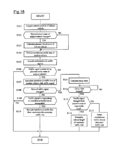
driving action to be taken for an event that the subject vehicle V1 passes
through a point at
which the planned travel route 1 of the subject vehicle V1 intersects with the
interference
traffic line 2 of another vehicle V3. The drive planning processor 21
calculates the positional
relationship between the subject vehicle VI and the other vehicle V3
associated with the
interference traffic line 2 and the change in the positional relationship
(degree of approaching).
On the basis of the time remaining for the subject vehicle Vito come into
contact with the
other vehicle V3, the drive planning processor 21 determines whether or not
the subject vehicle
V1 can pass through a point of intersection 8 between the planned travel route
1 and the
interference traffic line 2 without coming into contact with the other vehicle
V3.
[0063]
The drive planning processor 21 calculates an estimated time for each of the
subject
vehicle V1 and the other vehicle V3 to arrive at the point of intersection 8
and determines
whether or not the subject vehicle V1 can pass through the point of
intersection 8 with a
margin. Assume, for example, that the speed of the subject vehicle V1 is VV1,
the distance
from the subject vehicle Vito the point of intersection 8 is LI, the speed of
the other vehicle
V3 is VV2, and the distance from the other vehicle V3 to the point of
intersection 8 is L2.
[0064]
When the following Expression (1) is satisfied, the drive planning processor
21
determines that the subject vehicle V1 is highly likely to come into contact
with the other
vehicle V3 at the point of intersection 8, and determines that the driving
action at the point of
intersection 8 is "stopping." As used herein, Tthreshold represents a margin
time that is set with
consideration for the safety when vehicles cross each other.
I L2NV2¨Ll/VV1 I<Tihreshoid (1)
[0065]
On the other hand, when the following Expression (2) is satisfied, the drive
planning
processor 21 determines that the subject vehicle V1 is unlikely to come into
contact with the
other vehicle V3 at the point of intersection 8, and determines that the
driving action at the
point of intersection 8 is "traveling."
I L2NV2¨L1NV11>Tthreshoid (2)
19
CA 03012094 2018-07-20
=
=
[0066]
In the scene illustrated in FIG. 14, the drive planning processor 21
determines the
driving action to be taken for an event that the subject vehicle V1 passes
through a point at
which the planned travel route 1 of the subject vehicle V1 intersects with the
interference
traffic line 2 of another vehicle V3. The drive planning processor 21
calculates the positional
relationship between the subject vehicle V1 and the other vehicle V3
associated with the
interference traffic line 2 and the change in the positional relationship
(degree of approaching).
On the basis of the time remaining for the subject vehicle Vito come into
contact with the
other vehicle V3, the drive planning processor 21 determines whether or not
the subject vehicle
V1 can pass through a point of intersection 9 between the planned travel route
1 and the
interference traffic line 2 without coming into contact with the other vehicle
V3.
[0067]
The drive planning processor 21 calculates an estimated time for each of the
subject
vehicle V1 and the other vehicle V3 to arrive at the point of intersection 9
and determines
whether or not the subject vehicle VI can pass through the point of
intersection 9 with a
margin. Assume, for example, that the speed of the subject vehicle V1 is VV1,
the distance
from the subject vehicle Vito the point of intersection 9 is Li, the speed of
the other vehicle
V3 is VV3, and the distance from the other vehicle V3 to the point of
intersection 9 is L3.
The distance L3 may be calculated with reference to the curvature or the like
stored as a part of
the road information 223 and may also be calculated with reference to the
distance between
nodes which is stored as a part of the road information 223.
[0068]
When the following Expression (3) is satisfied, the drive planning processor
21
determines that the subject vehicle V1 is highly likely to encounter an event
of coming into
contact with the other vehicle V3 at the point of intersection 9, and
determines that the driving
action in this event is "stopping."
IL3/VV3¨L1NV 1 I<Tthreshoid (3)
[0069]
On the other hand, when the following Expression (4) is satisfied, the drive
planning
processor 21 determines that the subject vehicle V1 is unlikely to encounter
an event of coming
into contact with the other vehicle V3 at the point of intersection 9, and
determines that the
driving action in this event is "traveling."
IL3/VV3¨LI/VV1I>Tthreshoid (4)
CA 03012094 2018-07-20
[0070]
The drive planning processor 21 plans a series of driving actions of the
subject vehicle
V1 using the relationships with a plurality of interference traffic lines 2
that encounter the
planned travel route 1 of the subject vehicle V1 in a time-series manner. The
driving actions
refer to instructions in which commands of stopping or traveling are
associated with respective
interference traffic lines 2 that interfere with the planned travel route 1,
for example, from
when entering a certain area such as an intersection to when exiting the
certain area.
[0071]
When a determination of the traveling action is made for an interference
traffic line 2
and a determination of the stopping action or of being undeterminable is made
for another
interference traffic line 2 to be encountered next to the that interference
traffic line 2, the drive
planning processor 21 plans a driving action of controlling the subject
vehicle V1 to make a
stop at the point of intersection between the planned travel route 1 and the
interference traffic
line 2 for which the traveling action is determined. Even in a case in which
the traveling
action is once determined, when the interference traffic line 2 which the
subject vehicle V1
encounters next requires the stopping action or is undeterminable, the subject
vehicle V1 can
be controlled to make a stop at a position for which the traveling action is
determined. The
location for which the traveling action is determined is a location in which
the subject vehicle
VI is permitted to stay, and the subject vehicle V1 can therefore be
controlled to make a stop in
safety.
[0072]
When the point of intersection between the planned travel route 1 and an
interference
traffic line 2 for which a determination of the stopping action or of being
undeterminable is
made belongs to another interference traffic line 2, the drive planning
processor 21 plans a
driving action of controlling the subject vehicle V1 to make a stop at a
position which is
located at the further upstream side than the point of intersection and at
which stopping is
possible. Here, even in a case in which a determination of the stopping action
or of being
undeterminable is made for an interference traffic line 2, when the stop
position corresponding
to the interference traffic line 2 belongs to another interference traffic
line 2, the subject
vehicle V1 may obstruct another vehicle V3 traveling along the other
interference traffic line 2.
Thus, the stop position is inappropriate. The driving action is therefore
planned such that the
stop position is set at the upstream position at which stopping is possible,
rather than within the
other interference traffic line 2.
21
=
= CA 03012094 2018-07-20
1
[0073]
When a determination of the stopping action or of being undeterminable is made
for
an interference traffic line 2 and the point of intersection between the
interference traffic line 2
and the planned travel route 1 is close to or overlaps the point of
intersection between another
interference traffic line 2 and the planned travel route 1 so that these
points of intersection are
located within a predetermined distance, the drive planning processor 21 plans
a driving action
of controlling the subject vehicle Vito make a stop at a position which is
located at the further
upstream side than these points of intersection and at which stopping is
possible. Even in a
case in which a determination of the stopping action or of being
undeterminable is made for an
interference traffic line 2, when the stop position for the interference
traffic line 2 is close to or
overlaps the stop position for another interference traffic line 2, matching
with the
determination for the other interference traffic line 2 may have to be taken
into account. The
stop position is therefore inappropriate. The driving action is therefore
planned such that the
stop position is set at the upstream position at which stopping is possible,
rather than within the
other interference traffic line 2. This can reduce the cases of being
undeterminable.
Moreover, the load of determination processes can be reduced and the subject
vehicle V1 can
travel smoothly without repeating stop-and-go driving.
[0074]
When a determination of the traveling action is made for one interference
traffic line 2
and a determination of the stopping action or of being undeterminable is made
for another
interference traffic line 2 to be encountered next to the one interference
traffic line 2, the drive
planning processor 21 plans a driving action of controlling the subject
vehicle V1 to travel
along the one interference traffic line 2, provided that a degree of
separation between the one
interference traffic line 2 and the other interference traffic line 2 is a
predetermined value or
more. When traveling is permitted for one interference traffic line 2, but a
determination of
the stopping action or of being undeterminable is made for another
interference traffic line 2 to
be thereafter encountered, if the subject vehicle V1 is controlled to make a
stop at the upstream
one interference traffic line 2, a determination has to be made again as to
whether or not the
traveling along the other interference traffic line 2 is allowed, and the
subject vehicle VI may
interfere with the traffic stream of another vehicle V3 on the other
interference traffic line 2.
Thus, when separate events are determined in different ways: "traveling" at
the upstream side
and "stopping" at the downstream side, a driving action of controlling the
subject vehicle Vito
travel along the upstream interference traffic line 2 is planned thereby to
prevent the process
22
=
CA 03012094 2018-07-20
=
=
from being complexed.
[0075]
Here, when the road to which an interference traffic line 2 belongs is
included in the
detection range of the object detection device 230, the drive planning
processor 21 determines
a driving action and outputs it to the vehicle controller 210. The vehicle
controller 210
outputs control signals to the drive device 270 and the steering device 280
when a driving
action is output from the drive planning processor 21. This allows the drive
device 270
and/or the steering device 280 to be controlled in a completely automated
manner or in a form
of assisting with the driving operation (traveling operation) of the driver.
[0076]
On the other hand, when the road to which an interference traffic line 2
belongs is not
included in the detection range of the object detection device 230, the drive
planning processor
21 cannot determine a driving action because of an undeterminable state and
therefore does not
output a driving action to the vehicle controller 210. In this case, the
vehicle controller 210
does not output control signals to the drive device 270 and the steering
device 280, and the
control of the drive device 270 and steering device 280 performed in a
completely automated
manner or in a form of assisting with the driving operation of the driver is
suspended/canceled.
[0077]
The drive planning processor 21 determines a driving action to respond to the
necessary traffic line selected by the evaluation processor 11 and outputs the
driving action to
the vehicle controller 210, but does not determine a driving action for an
interference traffic
line 2 that is excluded from candidates for the necessary traffic line by the
evaluation processor
11. Here, the detection range for objects assigned to the object detection
device 230 includes
not only a range to which the necessary traffic line belongs but also a range
to which the
necessary traffic line does not belong. When detecting an object, the object
detection device
230 outputs the detection signal to the vehicle controller 210 even while the
control of the
drive device 270 and steering device 280 is performed in a completely
automated manner or in
a form of assisting with the driving operation of the driver. When the object
detection device
230 detects an object in a range to which the necessary traffic line does not
belong while the
control of the drive device 270 and steering device 280 is performed in a
completely automated
manner or the like, the vehicle controller 210 may suspend/cancel the control
of the drive
device 270 and steering device 280, which is performed in a completely
automated manner or
the like, in accordance with the positional relationship between the detected
object and the
23
= CA 03012094 2018-07-20
subject vehicle V1 and/or may output control signals for avoiding contact
between the subject
vehicle V1 and the object to the drive device 270 and the steering device 280.
[0078]
The output device 30 includes an output control processor 31. The output
control
processor 31 displays information using the display 251 as the output device
30. The output
control processor 31 displays information items representing the interference
traffic lines 2
selected by the evaluation processor in the order of encounters with the
subject vehicle V1 and
in a side-by-side fashion.
[0079]
The output control processor 31 is a computer comprising a read only memory
(ROM)
that stores programs for executing a process of displaying the information
items representing
the interference traffic lines, a central processing unit (CPU) as an
operation circuit that
executes the programs stored in the ROM to serve as the output device 30, and
a random access
memory (RAM) that serves as an accessible storage device.
[0080]
FIG. 15 is a flowchart for describing a process of selecting a necessary
traffic line in
accordance with the state of traffic signals using the evaluation processor 11
of the scene
evaluation device 10 (see FIG. 2 to FIG. 6). As illustrated in the flowchart,
first, in step S101,
the evaluation processor 11 acquires the current position of the subject
vehicle VI from the
navigation device 220. Then, in step S102, the evaluation processor 11
determines whether or
not the calculated planned travel route 1 of the subject vehicle VI is
changed. A negative
determination in this step is followed by step S104 while an affirmative
determination is
followed by step S103. In step S103, the evaluation processor 11 calculates
the planned
travel route 1 of the subject vehicle VI on the basis of the current position
of the subject
vehicle V1, the target route, and the map information 222.
[0081]
Then, in step S104, the evaluation processor 11 extracts the interference
traffic line 2
of another vehicle V3 on the basis of the calculated planned travel route 1 of
the subject
vehicle VI, the map information 222, and the road information 223. Then, in
step S105, the
evaluation processor 11 acquires information on traffic signals around the
subject vehicle V1
from the object detection device 230 or the like.
[0082]
Then, in step S106, the evaluation processor 11 determines whether or not a
traffic
24
CA 03012094 2018-07-20
=
signal corresponding to the planned travel route 1 of the subject vehicle V 1
is present. An
affirmative determination in this step is followed by step S107.
When a negative
determination is made, the process is ended.
[0083]
In step S107, the evaluation processor 11 refers to the road information 223
to
associate the interference traffic line 2 of the other vehicle V3 with a
traffic signal. Then, in
step S108, the evaluation processor 11 determines whether or not the state of
the traffic signal
changes between the previous process and the current process. An affirmative
determination
in this step is followed by step S111 while a negative determination is
followed by step S109.
[0084]
In step S109, the evaluation processor 11 determines whether or not the
traffic signal
corresponding to the interference traffic line 2 of the other vehicle V3 is in
an impassable state.
An affirmative determination in this step is followed by step S110. When a
negative
determination is made, the process is ended. Through this operation, the
interference traffic
line 2 corresponding to the traffic signal in a passable state is selected as
the necessary traffic
line. On the other hand, in step S110, the evaluation processor 11 excludes
the interference
traffic line 2 corresponding to the traffic signal in the impassable state
from candidates for the
necessary traffic line.
[0085]
In step S111, the evaluation processor 11 calculates a delay time from the
change of
the state of the traffic signal to the switching of the necessary traffic
line. Then, in step S112,
the evaluation processor 11 determines whether or not the above delay time has
elapsed after
the state of the traffic signal changed. An affirmative determination in this
step is followed
by step S113.
[0086]
In step S113, the evaluation processor 11 determines whether or not the
traffic signal
has changed from the passable state to the impassable state. An affirmative
determination in
this step is followed by step S114 while a negative determination is followed
by step S115.
[0087]
In step S114, the evaluation processor 11 gradually reduces the length of the
necessary
traffic line in accordance with the vehicle speed of the other vehicle V3
entering the
intersection along the interference traffic line 2, which is selected as the
necessary traffic line,
while the above delay dime elapses after the traffic signal changes from the
passable state to
=
CA 03012094 2018-07-20
=
the impassable state. On the other hand, in step S115, the evaluation
processor 11 selects the
interference traffic line 2 corresponding to the traffic signal, which has
changed from the
impassable state to the passable state, immediately after the change (without
waiting the elapse
of the above delay time). The process is thus completed.
[0088]
FIG. 16 is a flowchart for describing a process of selecting a necessary
traffic line in
accordance with the planned travel route 4 of the parallel traveling vehicle
V2 and the priority
level under the traffic rules using the evaluation processor 11 (see FIG. 7 to
FIG. 9). Steps
S201 to S204 illustrated in this flowchart are the same as steps S101 to S104
illustrated in the
flowchart of FIG 15, so repetitive description will be omitted and the already-
explained
description will be borrowed herein.
[0089]
Step S204 is followed by step S205 in which the evaluation processor 11
acquires
information on the positions, speeds, and movement vectors of other vehicles
around the
subject vehicle V1 from the object detection device 230 or the like. Then, in
step S206, the
evaluation processor 11 determines whether or not a parallel traveling vehicle
V2 traveling
parallel to the subject vehicle V1 exists, on the basis of the information
acquired from the
object detection device 230 or the like. An affirmative determination in this
step is followed
by step S207. When a negative determination is made, the process is ended.
[0090]
In step S207, the evaluation processor 11 calculates the planned travel route
4 of the
parallel traveling vehicle V2. Then, in step S208, the evaluation processor 11
determines
whether or not the interference traffic line 2 of another vehicle V3
intersecting with the
planned travel route 4 of the parallel traveling vehicle V2 exists.
An affirmative
determination in this step is followed by step S209. When a negative
determination is made,
the process is ended.
[0091]
In step S209, the evaluation processor 11 calculates the priority levels under
traffic
rules of the parallel traveling vehicle V2 the other vehicle V3 which is
traveling along the
interference traffic line 2. Then, in step S210, the evaluation processor 11
determines
whether or not the priority level of the parallel traveling vehicle V2 is
higher than the priority
level of the other vehicle V3 traveling along the interference traffic line 2.
An affirmative
determination in this step is followed by step S211. When a negative
determination is made,
26
CA 03012094 2018-07-20
=
the process is ended. Through this operation, the interference traffic line 2
along which the
other vehicle V3 having a higher priority level than that of the parallel
traveling vehicle V2
travels is selected as the necessary traffic line. On the other hand, in step
S211, the evaluation
processor 11 excludes the interference traffic line 2 along which the other
vehicle V3 having a
lower priority level than that of the parallel traveling vehicle V2 travels,
from candidates for
the necessary traffic line. The process is thus completed.
[0092]
FIG 17 is a flowchart for describing a process of selecting a necessary
traffic line in
accordance with the traffic rules on a road using the evaluation processor 11
(see FIG. 10 to
FIG. 12). Steps S301 to S304 illustrated in this flowchart are the same as
steps S101 to S104
illustrated in the flowchart of FIG. 15, so repetitive description will be
omitted and the
already-explained description will be borrowed herein.
[0093]
Step S304 is followed by step S305 in which the evaluation processor 11 refers
to the
road information 223 and the traffic rule information 224 to extract traffic
rules associated with
the lane to which the planned travel route 1 of the subject vehicle V1 belongs
and the lane to
which the interference traffic line 2 of another vehicle 3 belongs, and
extracts factors that
restrict the traffic of vehicles from among the extracted traffic rules.
[0094]
Then, in step S306, the evaluation processor 11 determines whether or not the
road to
which the interference traffic line 2 of another vehicle V3 belongs has a
restriction of WRONG
WAY for vehicles due to a traffic rule of ONE-WAY. An affirmative
determination in this
step is followed by step S307 while a negative determination is followed by
step S308. In
step S307, the evaluation processor 11 excludes the interference traffic line
2 in the opposite
direction to the traveling direction in conformity with the traffic rule of
ONE-WAY from
candidates for the necessary traffic line.
[0095]
Then, in step S308, the evaluation processor 11 determines whether or not the
road to
which the interference traffic line 2 of another vehicle V3 belongs has a
restriction of WRONG
WAY for vehicles due to a traffic rule of FOLLOW THE DIRECTION. An affirmative
determination in this step is followed by step S309 while a negative
determination is followed
by step S310. In step S309, the evaluation processor 11 excludes the
interference traffic line
2 of the other vehicle V3 from candidates for the necessary traffic line
because the other
27
=
CA 03012094 2018-07-20
=
vehicle V3 is prohibited from entering the road, to which the planned travel
route 1 of the
subject vehicle V1 belongs, due to the traffic rule of FOLLOW THE DIRECTION.
[0096]
Then, in step S310, the evaluation processor 11 determines whether or not the
road to
which the interference traffic line 2 of another vehicle V3 belongs has a
restriction of
temporary prohibition of entry of vehicles due to a traffic rule of STOP at
the crossing bar of a
railroad crossing 7. An affirmative determination in this step is followed by
step S311.
When a negative determination is made, the process is ended. In step S311, the
evaluation
processor 11 excludes the interference traffic line 2 of the other vehicle V3
from candidates for
the necessary traffic line because the other vehicle V3 is prohibited from
entering the road, to
which the planned travel route 1 of the subject vehicle V1 belongs, due to the
traffic rule of
STOP at the crossing bar of the railroad crossing 7.
[0097]
As described above, in the driving assistance method and apparatus according
to one
or more embodiments of the present invention, interference traffic lines 2 of
other vehicles V3
interfering with a planned travel route 1 of the subject vehicle V1 are
extracted, an interference
traffic line (necessary traffic line) 2 necessary for determining the driving
action of the subject
vehicle V1 is selected from among the extracted interference traffic lines 2
on the basis of at
least one of a road shape, a traffic rule, and a traffic situation, and the
driving action of the
subject vehicle V1 to respond to another vehicle V3 moving along the selected
interference
traffic line 2 is determined. Through this operation, the range for search
when determining
the driving action of the subject vehicle V1 can be set as an appropriate
range in accordance
with the necessity for determining the driving action of the subject vehicle
VI. It is therefore
possible to suppress the occurrence of a range in which perception by the
object detection
device 230 is not possible in the range for search when determining the
driving action and also
to suppress the occurrence of a situation in which the determination of a
driving action is
difficult. Moreover, the load of a determination process for the driving
action can be
mitigated by limiting the range for search when determining the driving action
of the subject
vehicle VI and it is therefore possible to reduce the time for the process and
prevent the
occurrence of a delay of the process.
[0098]
In the driving assistance method and apparatus according to one or more
embodiments
of the present invention, the necessary traffic line is selected from among
the extracted
28
CA 03012094 2018-07-20
1
interference traffic lines 2 on the basis of a state of the traffic signals 3A
to 3D corresponding
to the extracted interference traffic lines 2 of other vehicles V3 (see FIG.
3, FIG. 4, and FIG.
15). For example, the interference traffic line 2 corresponding to the traffic
signal in a
passable state is selected as the necessary traffic line from among the
extracted interference
traffic lines 2. This can exclude the interference traffic lines 2 through
which it is estimated
that other vehicles V3 do not pass in relation to the state of the traffic
signals 3A to 3C from
candidates for the necessary traffic line.
[0099]
In the driving assistance method and apparatus according to one or more
embodiments
of the present invention, when the state of the traffic signals corresponding
to the extracted
interference traffic lines 2 of other vehicles V3 changes, the interference
traffic line to be
selected is switched in accordance with the change of the state of the traffic
signals. For
example, when the state of the traffic signal corresponding to the selected
interference traffic
line 2 changes from the passable state to the impassable state, the selected
interference traffic
line 2 is switched to unselected one by gradually reducing the length. This
allows a driving
action to be planned which responds to a situation immediately after the state
of a traffic signal
changes, such as a situation in which another vehicle V3 travels along the
interference traffic
line 2 toward the planned travel route 1 of the subject vehicle V1 immediately
after the traffic
signal changes from the passable state to the impassable state.
[0100]
In the driving assistance method and apparatus according to one or more
embodiments
of the present invention, when the state of the traffic signal corresponding
to the selected
interference traffic line 2 of another vehicle V3 changes from the passable
state to the
impassable state, the length of the selected interference traffic line 2 is
gradually reduced at a
decrease amount per unit time in accordance with the vehicle speed of the
other vehicle V3
moving along the selected interference traffic line 2. Here, as the vehicle
speed of the other
vehicle V3 increases, the decrease amount per unit of the length of the
interference traffic line
2 as the necessary traffic line is reduced thereby to allow for a
determination of the driving
action to respond to the other vehicle V3 traveling along the interference
traffic line 2 at a high
speed.
[0101]
Here, until a certain period of time (e.g. several seconds) elapses from
immediately
after the traffic signal corresponding to the interference traffic line 2
selected as the necessary
29
=
CA 03012094 2018-07-20
=
=
traffic line changes from the passable state to the impassable state, the
probability remains that
another vehicle V3 travels along the interference traffic line 2. On the other
hand, the
probability that another vehicle V3 travels along an interference traffic line
2 increases in a
relatively short period of time immediately after the state of the traffic
signal corresponding to
the interference traffic line 2 changes from the impassable state to the
passable state (see FIG.
5). In the driving assistance method and apparatus according to one or more
embodiments of
the present invention, therefore, when the state of the traffic signal
corresponding to the
selected interference traffic line 2 of another vehicle V3 changes from the
passable state to the
impassable state, the selected interference traffic line 2 is switched to
unselected one after a
predetermined delay time elapses from the time point of the change. On the
other hand, when
the state of the traffic signal corresponding to an unselected interference
traffic line 2 changes
from the impassable state to the passable state, the unselected interference
traffic line 2 is
switched to selected one immediately after the change without providing a
delay time. This
allows a driving action to be determined which responds to another vehicle V3
traveling along
the interference traffic line 2 after the state of the traffic signal changes.
[0102]
In the driving assistance method and apparatus according to one or more
embodiments
of the present invention, when a parallel traveling vehicle V2 traveling
parallel to the subject
vehicle V1 exists, an interference traffic line 2 interfering with the planned
travel route 4 of the
parallel traveling vehicle V2 exists, and the parallel traveling vehicle V2
has a higher priority
level under the traffic rules than that of another vehicle V3 moving along the
interference
traffic line 2, the interference traffic line 2 is not selected (see FIG. 9).
This can exclude the
interference traffic lines 2 through which it is estimated that the other
vehicle V3 does not pass
in relation to the relationship with the priority level of the parallel
traveling vehicle V2 under
the traffic rules, from candidates for the necessary traffic line.
[0103]
In the driving assistance method and apparatus according to one or more
embodiments
of the present invention, the interference traffic line 2 along which movement
of another
vehicle V3 is restricted under a traffic rule, such as a traffic restriction
due to ONE-WAY,
FOLLOW THE DIRECTION, or a railroad crossing, is not selected (see FIG 10 to
FIG. 12).
This can exclude the interference traffic lines 2 through which it is
estimated that the other
vehicle V3 does not pass in relation to the traffic rule, from candidates for
the necessary traffic
line.
CA 03012094 2018-07-20
=
[0104]
Embodiments heretofore explained are described to facilitate understanding of
the
present invention and are not described to limit the present invention. It is
therefore intended
that the elements disclosed in the above embodiments include all design
changes and
equivalents to fall within the technical scope of the present invention.
[0105]
For example, in the above-described embodiments, the road shape has been
exemplified with reference to a road having an intersection, T-junction,
and/or railroad crossing,
but the necessary traffic line may also be selected on the basis of the
information regarding
other road shapes, such as the number of lanes and a junction of three or more
streets. In the
above-described embodiments, the traffic rules have been exemplified with
reference to the
traffic restriction due to traffic signals, the traffic rule that vehicles
traveling straight ahead or
turning left on an intersection have higher priority levels than those of
oncoming vehicles
turning right, the traffic restriction due to ONE-WAY, the traffic restriction
due to FOLLOW
THE DIRECTION, and the traffic restriction due to a railroad crossing, but the
necessary
traffic line may also be selected on the basis of the information regarding
other traffic rules,
such as traffic restrictions due to STOP and a priority road. Furthermore, the
traffic situation
has been exemplified with reference to a situation in which a parallel
traveling vehicle exists,
but the necessary traffic line may also be selected on the basis of the
information regarding
other traffic situations such as a situation in which a number of oncoming
vehicles exist (i.e. a
situation in which, when the subject vehicle turns left, the interference
traffic lines of vehicles
traveling straight ahead from the right side can be excluded from candidates
for the necessary
traffic line).
[0106]
The scheme of determining a driving action is not limited to the above-
described
scheme and other appropriate schemes can also be selected.
[Description of Reference Numerals]
[0107]
1 Planned travel route
2 Interference traffic line
3A to 3D Traffic signals
4 Planned travel route
31
CA 03012094 2018-07-20
= =
7 Railroad crossing
100 Driving assistance apparatus
21 Drive planning processor
Vi Subject vehicle
V2 Parallel traveling vehicle
V3 Another vehicle
32