Note: Descriptions are shown in the official language in which they were submitted.
84345861
ADDITIVE MANUFACTURING SYSTEM IMPLEMENTING
HARDENER PRE-IMPREGNATION
Technical Field
[0001] The present disclosure relates generally to a manufacturing system and,
more particularly,
to an additive manufacturing system implementing hardener pre-impregnation.
Background
[0002] Traditional additive manufacturing is a process of creating three-
dimensional parts by
depositing overlapping layers of material under the guided control of a
computer. A common form
of additive manufacturing is known as fused deposition modeling (FDM). Using
FDM, a
thermoplastic is passed through and liquified within a heated print head. The
print head is moved in
a predefined trajectory (a.k.a., a tool path) as the material discharges from
the print head, such that
the material is laid down in a particular pattern and shape of overlapping 2-
dimensional layers. The
material, after exiting the print head, cools and hardens into a final form. A
strength of the final
form is primarily due to properties of the particular thermoplastic supplied
to the print head and a 3-
dimensional shape formed by the stack of 2-dimensional layers.
[0003] A recently developed improvement over traditional FDM manufacturing
involves the use
of continuous fibers embedded within material discharging from the print head
(a.k.a., Continuous
Fiber 3D Printing ¨ CF3DTm). In particular, a matrix is supplied to the print
head and discharged
(e.g., extruded and/or pultruded) along with one or more continuous fibers
also passing through the
same head at the same time. The matrix can be a traditional thermoplastic, a
powdered metal, a
liquid matrix (e.g., a UV curable and/or two-part resin), or a combination of
any of these and other
known matrixes. Upon exiting the print head, a cure enhancer (e.g., a UV
light, an ultrasonic
emitter, a heat source, a catalyst supply, etc.) is activated to initiate
and/or complete curing of the
matrix. This curing occurs almost immediately, allowing for unsupported
structures to be fabricated
in free space. And when fibers, particularly continuous fibers, are embedded
within the structure, a
strength of the structure may be multiplied beyond the matrix-dependent
strength. An example of
this technology is disclosed in U.S. Patent 9,511,543 that issued to Tyler on
December 6, 2016 ("the
'543 patent").
CA 3012238 2018-07-24
84345861
100041 In some applications involving opaque fibers (e.g., carbon fibers),
high-density fibers,
high-concentrations of fibers, large-diameter fibers, etc., it can be
difficult for the matrix material
located at a center of the corresponding fiber bundle to receive sufficient
cure enhancement (e.g.,
sufficient cure energy, catalyst, etc.). If unaccounted for, the resulting
structure may lack strength
and/or sag undesirably.
10005] The disclosed system is directed to addressing one or more of the
problems set forth above
and/or other problems of the prior art.
Summary
10006] In one aspect, the present disclosure is directed to a method of
additively manufacturing a
composite structure. The method may include directing a continuous
reinforcement into a print
head, and coating the continuous reinforcement with a first matrix component
inside of the print
head. The method may further include coating the continuous reinforcement with
a second matrix
component, discharging the continuous reinforcement through a nozzle of the
print head, and
moving the print head in multiple dimensions during the discharging. The first
and second matrix
components interact to cause hardening of a matrix around the continuous
reinforcement.
10007] In another aspect, the present disclosure is directed to a system for
additively
manufacturing a composite structure. The system may include a support, and a
print head connected
to an end of the support. The print head may have a body with a chamber, in
which a continuous
reinforcement is coated with one of a resin and a catalyst. The print head may
also include a nozzle
connected to a discharge end of the body and configured to discharge the
continuous reinforcement
coated in both the resin and the catalyst. The system may further include a
controller in
communication with the support and the head. The controller may be configured
to selectively cause
the support to move the head in multiple dimensions during discharge of the
continuous
reinforcement from the nozzle, according to specifications for the composite
structure.
[0008] In yet another aspect, the present disclosure is directed to a prepreg
material for use in
additively manufacturing a composite structure. The prepreg material may
include a continuous
reinforcement, and a catalyst of a multi-part matrix. The multi-part matrix,
which also includes at
least a resin, is curable around the continuous reinforcement to form the
composite structure. The
reinforcement is at least partially saturated with the catalyst and
substantially free of the resin prior
CA 3012238 2018-07-24
84345861
-3-
to manufacture of the composite structure, and the reinforcement makes up
about 35-70% of the composite
structure. The catalyst makes up about .1-10% of the composite structure.
[0008a] According to another embodiment, there is provided a method of
additively manufacturing a
composite structure, comprising: directing a continuous reinforcement into a
print head; coating the continuous
reinforcement with a first matrix component inside of the print head; coating
the continuous reinforcement with a
second matrix component that is different from the first matrix component;
discharging the continuous
reinforcement through a nozzle of the print head; and moving the print head in
multiple dimensions during the
discharging; wherein: the first and second matrix components interact to cause
hardening of a matrix around the
continuous reinforcement; the first matrix component is a resin, and the
second matrix component is one of a
catalyst, a hardener, and an initiator; and coating the continuous
reinforcement with the second matrix
component includes coating the continuous reinforcement with the second matrix
component before the
continuous reinforcement has been coated with the first matrix component.
[0008b] According to another embodiment, there is provided a method of
additively manufacturing a
composite structure, comprising: directing a continuous reinforcement that has
been coated with a catalyst into a
print head; coating the continuous reinforcement with a resin that is
different from the catalyst inside of the print
head; discharging the continuous reinforcement through a nozzle of the print
head; and moving the print head in
multiple dimensions during the discharging.
[0008c] According to another embodiment, there is provided a method of
additively manufacturing a
composite structure, comprising: directing a continuous reinforcement through
a catalyst bath inside a print head;
directing the continuous reinforcement through a resin bath inside of the
print head; discharging the continuous
reinforcement through a nozzle of the print head; and moving the print head in
multiple dimensions during the
discharging.
Brief Description of the Drawings
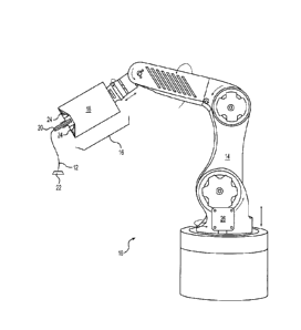
[0009] Fig. 1 is a diagrammatic illustration of an exemplary disclosed
manufacturing system; and
[0010] Figs. 2-4 are diagrammatic illustrations an exemplary disclosed
heads that may be used in conjunction
with the manufacturing system of Fig. 1.
Detailed Description
[0011] Fig. 1 illustrates an exemplary system 10, which may be used to
continuously manufacture a
composite structure 12 having any desired cross-sectional shape (e.g.,
circular, polygonal, etc.). System 10 may
include at least a support 14 and a head 16. Head 16 may have a body 18 that
is coupled to and moved by
support 14, and a nozzle 20 located at an opposing discharge end of body 18.
In the disclosed embodiment of
Fig. 1, support 14 is a robotic arm capable of moving head 16 in multiple
directions during fabrication of
structure 12, such that a resulting longitudinal axis of
CA 3012238 2019-06-14
84345861
structure 12 is three-dimensional. It is contemplated, however, that support
14 could alternatively be
an overhead gantry or a hybrid gantry/arm also capable of moving head 16 in
multiple directions
during fabrication of structure 12. Although support 14 is shown as being
capable of 6-axis
movements, it is contemplated that any other type of support 14 capable of
moving head 16 in the
same or in a different manner could also be utilized, if desired. In some
embodiments, a drive may
mechanically couple head 16 to support 14, and may include components that
cooperate to move
and/or supply power or materials to head 16.
10012] Body 18 may be configured to receive or otherwise contain a matrix
material. The matrix
material may include any type of matrix material (e.g., a liquid resin, such
as a zero volatile organic
compound resin; a powdered metal; etc.) that is curable. Exemplary resins
include thermosets,
single- or multi-part epoxy resins, polyester resins, cationic epoxies,
acrylated epoxies, urethanes,
esters, thermoplastics, photopolymers, polyepoxides, thiols, alkenes, thiol-
enes, and more. In one
embodiment, the matrix material inside body 18 may be pressurized, for example
by an external
device (e.g., an extruder or another type of pump - not shown) that is fluidly
connected to head 16
via a corresponding conduit (not shown). In another embodiment, however, the
pressure may be
generated completely inside of body 18 by a similar type of device. In yet
other embodiments, the
matrix material may be gravity-fed through and/or mixed within body 18. In
some instances, the
matrix material inside body 18 may need to be kept cool and/or dark to inhibit
premature curing;
while in other instances, the matrix material may need to be kept warm for the
same reason. In
either situation, body 18 may be specially configured (e.g., insulated,
chilled, and/or warned) to
provide for these needs.
[0013] The matrix material may be used to coat, encase, or otherwise surround
any number of
continuous reinforcements (e.g., separate fibers, tows, rovings, and/or sheets
of material) and,
together with the reinforcements, make up at least a portion (e.g., a wall) of
composite structure 12.
The reinforcements may be stored within (e.g., on separate internal spools -
not shown) or otherwise
passed through body 18 (e.g., fed from external spools 21 ¨ See Figs. 2-4).
When multiple
reinforcements are simultaneously used, the reinforcements may be of the same
type and have the
same diameter and cross-sectional shape (e.g., circular, square, flat, etc.),
or of a different type with
different diameters and/or cross-sectional shapes. The reinforcements may
include, for example,
carbon fibers, vegetable fibers, wood fibers, mineral fibers, glass fibers,
metallic wires, optical tubes,
etc. It should be noted that the term "reinforcement" is meant to encompass
both structural and non-
CA 3012238 2018-07-24
84345861
-5-
structural types of continuous materials that can be at least partially
encased in the matrix material
discharging from nozzle 20.
[0014] The reinforcements may be exposed to (e.g., coated with) the matrix
material while the
reinforcements are passing through body 18. The matrix material, dry
reinforcements, and/or
reinforcements that are already exposed to the matrix material (e.g., wetted
reinforcements) may be
transported into body 18 in any manner apparent to one skilled in the art.
[0015] The matrix material and reinforcement may be discharged from nozzle 20
via at least two
different modes of operation. In a first mode of operation, the matrix
material and reinforcement are
extruded (e.g., pushed under pressure and/or mechanical force) from nozzle 20,
as head 16 is moved
by support 14 to create the 3-dimensional shape of structure 12. In a second
mode of operation, at
least the reinforcement is pulled from nozzle 20, such that a tensile stress
is created in the
reinforcement during discharge. In this mode of operation, the matrix material
may cling to the
reinforcement and thereby also be pulled from nozzle 20 along with the
reinforcement, and/or the
matrix material may be discharged from nozzle 20 under pressure along with the
pulled
reinforcement. In the second mode of operation, where the matrix material is
being pulled from
nozzle 20, the resulting tension in the reinforcement may increase a strength
of structure 12, while
also allowing for a greater length of unsupported material to have a
straighter trajectory (i.e., the
tension may act against the force of gravity to provide free-standing support
for structure 12).
[0016] The reinforcement may be pulled from nozzle 20 as a result of head 16
moving away from
an anchor point 22. In particular, at the start of structure-formation, a
length of matrix-impregnated
reinforcement may be pulled and/or pushed from nozzle 20, deposited onto
anchor point 22, and
cured, such that the discharged material adheres to anchor point 22.
Thereafter, head 16 may be
moved away from anchor point 22, and the relative movement may cause the
reinforcement to be
pulled from nozzle 20. It should be noted that the movement of reinforcement
through body 18
could be assisted (e.g., via one or more internal and/or external feed
mechanisms ¨ not shown), if
desired. However, the discharge rate of reinforcement from nozzle 20 may
primarily be the result of
relative movement between head 16 and anchor point 22, such that tension is
created and maintained
within the reinforcement. It is contemplated that anchor point 22 could be
moved away from head
16 instead of or in addition to head 16 being moved away from anchor point 22.
[0017] One or more cure enhancers (e.g., a UV light, an ultrasonic emitter, a
laser, a heater, a
catalyst dispenser, etc.) 24 may be mounted proximate (e.g., within, on,
and/or trailing from) head 16
CA 3012238 2018-07-24
84345861
(e.g., at a base of body 18, inside of body 18, outside of body 18, or
otherwise adjacent nozzle 20)
and configured to enhance a cure rate and/or quality of the matrix material as
it is discharged from
head 16. Cure enhancer 24 may be controlled to selectively expose internal
and/or external surfaces
of structure 12 to energy (e.g., UV light, electromagnetic radiation,
vibrations, heat, a chemical
catalyst, hardener, or initiator, etc.) during the formation of structure 12.
The energy may increase a
rate of chemical reaction occurring within the matrix material, sinter the
material, harden the
material, or otherwise cause the material to cure as it discharges from head
16.
[0018] A controller 26 may be provided and communicatively coupled with
support 14, head 16,
and any number and type of cure enhancers 24. Controller 26 may embody a
single processor or
multiple processors that include a means for controlling an operation of
system(s) 10 and/or 12.
Controller 26 may include one or more general- or special-purpose processors
or microprocessors.
Controller 26 may further include or be associated with a memory for storing
data such as, for
example, design limits, performance characteristics, operational instructions,
matrix characteristics,
reinforcement characteristics, characteristics of structure 12, and
corresponding parameters of each
component of system 10. Various other known circuits may be associated with
controller 26,
including power supply circuitry, signal-conditioning circuitry,
solenoid/motor driver circuitry,
communication circuitry, and other appropriate circuitry. Moreover, controller
26 may be capable of
communicating with other components of system 10 via wired and/or wireless
transmission.
[0019] One or more maps may be stored in the memory of controller 26 and used
during
fabrication of structure 12. Each of these maps may include a collection of
data in the form of
lookup tables, graphs, and/or equations. In the disclosed embodiment, the maps
are used by
controller 26 to determine desired characteristics of cure enhancers 24, the
associated matrix, and/or
the associated reinforcements at different locations within structure 12. The
characteristics may
include, among others, a type, quantity, and/or configuration of reinforcement
and/or matrix to be
discharged at a particular location within structure 12, and/or an amount,
shape, and/or location of
desired curing. Controller 26 may then correlate operation of support 14
(e.g., the location and/or
orientation of head 16) and/or the discharge of material from nozzle 20 (a
type of material, desired
performance of the material, cross-linking requirements of the material, a
discharge rate, etc.) with
the operation of cure enhancers 24 such that structure 12 is produced in a
desired manner.
[0020] In some applications, care must be taken to ensure that each of the
fibers passing through
head 16 are sufficiently coated with matrix material (i.e., coated sufficient
to ensure proper bonding
CA 3012238 2018-07-24
84345861
-7-
and curing) prior to discharge from nozzle 20. As shown in Fig. 2, the fibers
may be exposed to the
matrix material during travel through one or more chambers 28 that are located
inside of body 18.
[0021] In the embodiment of Fig. 2, the matrix material being applied to the
reinforcement inside
of head 16 is a multi-part matrix. In particular, the matrix includes a first
matrix component (e.g., an
epoxy resin, a polyester resin, a vinylester resin, or another type of resin)
and at least a second
matrix component (e.g., a hardener, a catalyst, or another initiator) that,
under controlled conditions,
together react or causes a reaction to form a cured and hardened matrix
encasing the associated
reinforcements. At least two separate chambers 28 are located inside of body
18 of Fig. 2, for
separately coating the reinforcements with the first and second matrix
components. These chambers
28 include a first chamber 28a that is sequentially arranged with a second
chamber 28b. in relation to
a travel direction of the reinforcement(s) through head 16 (e.g., from spool
21 to nozzle 20). In this
example, first chamber 28a contains one of the first and second matrix
components, while second
chamber 28b contains the other of the first and second matrix components. It
should be noted that
both sequential orders of the first and second matrix components within body
18 are contemplated in
this disclosure.
[0022] The first and/or second matrix components may be supplied to the
corresponding
chamber(s) 28a, 28b in several different ways. For example, one or both of the
first and second
matrix components may be provided as a gas-, a liquid-, or a powder-stream via
a jet 30 (see Fig. 4);
as a liquid bath via a supply inlet 32 or jet 30; as a suspended powder via a
pressurized conduit 34,
supply inlet 32, or jet 30; or in another manner known in the art. In some
embodiments, a regulating
device 36 (e.g., opposing rollers, a squeegee, a wiper, a brush, an air jet,
etc.) may be disposed
between first and second chambers 28a and 28b (and/or downstream of second
chamber 28b) to
remove excess matrix component from the reinforcements prior to the coated
reinforcements
entering second chamber 28b (and/or just prior to the coated reinforcement
entering nozzle 20). In
this way, mixing of any excess matrix component clinging to the
reinforcements, with the
subsequent supply of matrix component inside of second chamber 28b (and
corresponding premature
curing of the mixture inside of second chamber 28b), may be inhibited. In some
applications, a
mechanical means (e.g., a tube surrounding the catalyst-coated reinforcement
and extending to jet(s)
30) may be used to inhibit premature mixing of the catalyst with the base
matrix. In other
embodiments, curing of the matrix components may primarily initiate or proceed
rapidly only when
a temperature of the matrix components exceeds a minimum threshold. regardless
of undesired
CA 3012238 2018-07-24
84345861
-8-
mixing inside second chamber 28b. In these embodiments, body 18 of head 16 may
be maintained
below the minimum threshold, to inhibit premature curing.
100231 It should be noted that, while a single jet 30 is shown as being
oriented generally
orthogonal to an axis of the reinforcement passing through head 16, it is
contemplated that any
number of jets 30 could be utilized and oriented at a different angle, if
desired. For example, jet(s)
30 could be tilted downward toward nozzle 20 and at an oblique angle relative
to the axis of the
reinforcement. This may help to reduce splashing and contamination of catalyst
within matrix
reservoir 28, in some applications. In addition, it is contemplated that a
purge fluid (e.g., mineral
oil) could be periodically (e.g., at a start and/or end of a fabrication
event) passed through jet(s) 30,
if desired.
100241 As the reinforcements pass through first and second chambers 28a, 28b,
the reinforcements
may be coated with overlapping inner and outer layers of the first and second
matrix components. In
some embodiments, the layers remain substantially separated until the
reinforcements reach nozzle
20. In other embodiments, some mixing of the first and second matrix
components at their
corresponding boundaries occurs, prior to the reinforcements reaching nozzle
20. Regardless of how
much mixing occurs upstream of nozzle 20, the mechanical motion of the coated
reinforcements
converging and being discharged through nozzle 20 may enhance mixing of the
first and second
matrix components. And upon exiting nozzle 20, curing may begin or speed up as
both a result of
the increased mixing and exposure to energy from cure enhancers 24. It is
contemplated that, in
some applications, cure enhancers 24 may be unnecessary, as the mixing of the
two matrix
components (and/or exposure of the mixed components to ambient conditions) at
nozzle 20 may be
sufficient for complete curing. It is further contemplated that nozzle 20
(e.g., a tip end of nozzle 20)
could be energized (e.g., heated, vibrated, etc.) to increase a rate of cure,
if desired.
100251 In some embodiments, in addition to the two matrix components described
above, an
additive or third matrix component may be mixed into one or both of the first
and second matrix
components. The additive may include, for example, a filler and/or an
additional or different
catalyst. For instance, a UV cure initiator (e.g., different from the second
matrix component) could
be mixed into the first matrix component, if desired. The UV cure initiator
may be sufficient to raise
a temperature of the matrix mixture coating the reinforcements to the minimum
threshold
temperature discussed above, upon exposure to light energy from cure enhancers
24. Thereafter, the
CA 3012238 2018-07-24
84345861
second matrix matrix component in the mixture coating the reinforcements may
be triggered to cause full
and complete curing of the first matrix component in the mixture.
[0026] In some situations, the reinforcements being fed into head 16 may
include many (e.g.,
thousands) of individual fibers that are bound, woven, twisted or otherwise
gathered together. In
these situations, it can be difficult to ensure that a sufficient amount of
the first and/or second matrix
components coats each of the individual fibers. This may be even more
difficult when large tows or
thick ribbons of fibers are passed through head 16 at high speeds. For this
reason, head 16 may be
equipped with one or more fiber-teasing mechanisms 38 that help to separate
and/or flatten the tows
or ribbons, such that the matrix components can penetrate to the centermost
fibers more thoroughly
and/or quicker. Mechanisms 38 may be located inside and/or outside of body 18,
at a position
upstream of and/or between chamber(s) 28. Mechanisms 38 may include, for
example, brushes, a
tortuous path of protrusions (e.g., rollers, fingers, or stationary bumps),
air and/or resin jets, and
other similar devices.
[0027] Fig. 3 illustrates an alternative embodiment of head 16 that is also
configured to discharge
reinforcements coated in a multi-part matrix. In this embodiment, however,
body 18 includes a
single chamber 28. The single chamber 28 may hold either the first matrix
component or the second
matrix component discussed above, with or without the additive. The remaining
matrix component
may already coat the reinforcement and be supplied to head 16 as a prepreg
material (e.g., from
spool 21 and/or from an upstream and offboard coating chamber ¨ not shown). In
other words, head
16 may be configured to apply only part of the multi-part matrix, with the
remaining part(s) already
being applied to the reinforcements at an earlier time and/or upstream
location. In this embodiment,
care should be taken to ensure that the prepreg material is kept at conditions
that extend life of the
material prior to the material being fed into head 16, for example, in dry,
cool, and/or dark
conditions.
[0028] Fig. 4 illustrates another embodiment having a single-chamber head 16,
which is also
configured to discharge reinforcements coated in a multi-part matrix. Like the
embodiment of Fig.
3, the single chamber 28 of Fig. 4 may hold either the first matrix component
or the second matrix
component discussed above (with or without the additive). The remaining matrix
component may
be injected, sprayed, or otherwise advanced (e.g., via jet 30, inlet 32,
and/or conduit 34) into head 16
at a discharge end. In one example, the remaining matrix component is advanced
into body 18 at a
discharge end of chamber 28, just upstream of nozzle 20. In another
embodiment, the remaining
CA 3012238 2018-07-24
84345861
-10-
matrix component is advanced directly into nozzle 20. The location of the
matrix component
advancement should be far enough upstream of the tip end of nozzle 20 to
ensure adequate mixing of
the matrix components, yet downstream enough to inhibit premature curing
inside of nozzle 20. It is
contemplated that the reinforcements fed into head 16, in the embodiment of
Fig. 4, may include dry
fibers or fibers pre-impregnated with another material (e.g., the additive),
if desired.
[0029] Regardless of the particular embodiment (e.g., the embodiment of Fig.
2, Fig. 3, or Fig. 4)
utilized to fabricate structure 12, structure 12 may be comprised of at least
three primary
constituents. As described above, these constituents may include the
reinforcement (e.g., the
continuous fibers, tows, ribbons, sheets, etc.), the first matrix component
(e.g., the resin, such as an
epoxy resin), and the second matrix component (e.g., the hardener, catalyst,
initiator, etc.). And in
some embodiments, the additive (e.g., the UV cure initiator) may be mixed into
the first and/or
second matrix components at any desired point in the manufacturing process.
For the purposes of
this disclosure, the reinforcement may comprise about (e.g., within
engineering tolerances) 35-70%
(e.g., by weight and/or volume) of structure 12; the first matrix component
may comprise about 30-
50% of structure 12, and the second matrix component may comprise about .1-10%
of structure 12.
In embodiments including the additive, the additive may comprise about 0-10%.
Industrial Applicability
[0030] The disclosed system may be used to continuously manufacture composite
structures
having any desired cross-sectional shape, length, density, and/or strength.
The composite structures
may include any number of different reinforcements of the same or different
types, diameters,
shapes, configurations, and consists, and/or any number of different matrixes.
Operation of system
will now be described in detail.
[0031] At a start of a manufacturing event, information regarding a desired
structure 12 may be
loaded into system 10 (e.g., into controller 26 that is responsible for
regulating operation of support
14, cure enhancer(s) 24, jet(s) 30, regulating device(s) 36, fiber-teasing
mechanism(s) 38, and/or any
other associated components). This information may include, among other
things, a size (e.g.,
diameter, wall thickness, length, etc.), a contour (e.g., a trajectory),
surface features (e.g., ridge size,
location, thickness, length; flange size, location, thickness, length; etc.),
connection geometry (e.g.,
locations and sizes of couplings, tees, splices, etc.), location-specific
matrix stipulations, location-
specific reinforcement stipulations, desired cure rates, cure locations, cure
shapes, cure amounts, etc.
CA 3012238 2018-07-24
84345861
-11-
It should be noted that this information may alternatively or additionally be
loaded into system 10 at
different times and/or continuously during the manufacturing event, if
desired.
[0032] Based on the component information, a specific nozzle 20 and/or cure
enhancer
configuration may be connected to head 16 (e.g., to the discharge end of body
18), and one or more
different (e.g., different sizes, shapes, and/or types of) reinforcements
and/or matrix materials may
be selectively installed within system 10 and/or continuously supplied into
nozzle 20. The
corresponding reinforcements (e.g., prepreg or dry fibers, tows, ribbons, or
sheets) may be passed
through one or more fiber-teasing mechanisms 38 (e.g., between the bristles of
adjacent brushes,
and/or over or around protrusions, etc.) and nozzle 20, and thereafter
connected to a pulling machine
(not shown) and/or to a mounting fixture (e.g., to anchor point 22).
Installation of the matrix
material may include filling chamber(s) 28 and/or coupling of an extruder (not
shown) to head 16.
[0033] Head 16 may be moved by support 14 under the regulation of controller
26 to cause matrix-
coated reinforcements to be placed against or on a corresponding anchor point
22. Cure enhancers
24 may then be selectively activated (e.g., turned on/off and/or intensity-
adjusted by controller 26) to
cause hardening of the matrix material surrounding the reinforcements, thereby
bonding the
reinforcements to anchor point 22.
[0034] The component information may then be used to control operation of
system 10. For
example, the reinforcements may be pulled through fiber-teasing mechanism(s)
38; separated and/or
flattened; submerged within the first matrix component, wrung out by
regulating device 36;
submerged within the second matrix component; and then discharged from nozzle
20. Controller 26
selectively cause support 14 to move head 16 in a desired manner at this time,
such that an axis of
the resulting structure 12 follows a desired trajectory (e.g., a free-space,
unsupported, 3-D
trajectory). In addition, cure enhancers 24 may be selectively activated by
controller 26 during
material discharge to initiate, speed up, or complete hardening of the liquid
matrix mixture. Once
structure 12 has grown to a desired length, structure 12 may be disconnected
(e.g., severed) from
head 16 in any desired manner.
[0035] It will be apparent to those skilled in the art that various
modifications and variations can
be made to the disclosed systems and head. Other embodiments will be apparent
to those skilled in
the art from consideration of the specification and practice of the disclosed
systems and heads. It is
intended that the specification and examples be considered as exemplary only,
with a true scope
being indicated by the following claims and their equivalents.
CA 3012238 2018-07-24