Note: Descriptions are shown in the official language in which they were submitted.
CA 03012457 2018-07-24
WO 2017/136185 PCT/US2017/014687
- 1 -
Control of Hydraulic Power Flowrate for Managed Pressure Drilling
-by-
Paul R. Northam & Walter S. Dillard
FIELD OF THE DISCLOSURE
[0001] The disclosure relates to a method and apparatus to control
hydraulic chokes in
a managed pressure drilling system.
BACKGROUND OF THE DISCLOSURE
[0002] Several controlled pressure drilling techniques are used to drill
wellbores with a
closed-loop drilling system. In general, controlled pressure drilling includes
managed
pressure drilling (MPD), underbalanced drilling (UBD), and air drilling (AD)
operations.
[0003] In the Managed Pressure Drilling (MPD) technique, the drilling
system uses a
closed and pressurizable mud-return system, a rotating control device (RCD),
and a
choke manifold to control the wellbore pressure during drilling. The various
MPD
techniques used in the industry allow operators to drill successfully in
conditions where
conventional technology simply will not work by allowing operators to manage
the
pressure in a controlled fashion during drilling.
[0004] During drilling, for example, the bit drills through a formation,
and pores
become exposed and opened. As a result, formation fluids (i.e., gas) can mix
with the
drilling mud. The drilling system then pumps this gas, drilling mud, and the
formation
cuttings back to the surface. As the gas rises up the borehole in an open
system, the
gas expands and hydrostatic pressure decreases, meaning more gas from the
formation may be able to enter the wellbore. If the hydrostatic pressure is
less than the
formation pressure, then even more gas can enter the wellbore.
[0005] A core function of managed pressure drilling attempts to control
kicks or
influxes of fluids as described above. This can be achieved using an automated
choke
response in a closed and pressurized circulating system made possible by the
rotating
control device. A control system controls the chokes with an automated
response by
monitoring flow in and out of the well, and software algorithms in the control
system
seek to maintain a mass flow balance. If a deviation from mass balance is
identified,
the control system initiates an automated choke response that changes the
well's
annular pressure profile and thereby changes the wellbore's equivalent mud
weight.
CA 03012457 2018-07-24
WO 2017/136185 PCT/US2017/014687
- 2 -
This automated capability of the control system allows the system to perform
dynamic
well control or CBHP techniques.
[0006] The chokes of the manifold have a non-linear response. This can make
it
difficult to determine the true position of the chokes and properly control
pressure and
flow as conditions change. Additionally, hydraulic power is typically supplied
remotely
to the chokes by a hydraulic power unit (HPU). Typically, the power unit has a
hydraulic
pump, an accumulator, and a directional control valve (which can be solenoid-
activated). During managed pressure drilling, the solenoid valve is driven by
a feedback
control loop that uses position measurements of the choke's piston. In the
early
morning hours of operation, the temperature inside the accumulator and unit's
hydraulic
reservoir reaches the lowest point of the day. With this low temperature, the
nitrogen
gas energy in the accumulator is low, and the viscosity of the hydraulic fluid
us high.
The lower internal Nitrogen pressure of the accumulator allows more hydraulic
fluid to
enter the accumulator while reaching the set hydraulic system pressure.
[0007] Having a greater percentage of hydraulic fluid and less energized
gas in the
accumulator reduces the velocity of hydraulic fluid leaving the accumulator.
Consequently, the morning fluid flowrate that drives the choke is slower, and
the
response of the choke appears more sluggish than it would at hotter times of
the day,
when accumulator pressure rises and viscosity drops. The daily temperature
cycle
causes the MPD system to behave differently depending on the time of day.
Another
factor that changes hydraulic fluid temperature is the average work load over
time. For
example, when the MPD system is opening/closing the chokes more frequently,
the
hydraulic fluid temperature will rise.
[0008] Unfortunately, operators are typically trained to use the equipment
at a certain
operating temperature. Therefore, the operators may tend to find that there is
a
different and unexpected behavior at another temperature. In particular, the
set control
variables suited for lower temperatures will cause the choke response to be
faster in the
afternoon due to the increased Nitrogen energy in the accumulator bottle and
the lower
viscosity of the hydraulic fluid. This increases the chances of overshooting
the target
choke position. In fact, choke opening and closing times may vary by around
30%
throughout the day, or even depending on whether the equipment is in shade or
direct
sunlight. Likewise, the set control variables suited for higher temperatures
will cause
CA 03012457 2018-07-24
WO 2017/136185 PCT/US2017/014687
- 3 -
the choke response to be slower to reach set point values as operations
continues into
the night and morning hours, as a cold front suddenly drops temperatures, etc.
[0009] There is a needle valve located in the hydraulic power unit that is
used to
throttle the flow leading up to the chokes. The needle valve is meant to be
set to a
position that will allow an optimal flowrate to drive the chokes. Usually, the
needle valve
is set at the beginning of a job or during a factory acceptance test.
[0010] It is recognized that electric actuation of the chokes may have
faster response
times (i.e., closing and opening times for the chokes) when compared to
hydraulic
actuation. However, electric actuation on the drilling rig may not be
desirable or even
possible for various reasons so that hydraulic actuation may be preferred.
Therefore,
what is needed is a way to mitigate any timing differences that may occur in
the choke
response in a choke manifold for a drilling system as temperatures change.
Therefore,
the subject matter of the present disclosure is directed to overcoming, or at
least
reducing the effects of, one or more of the problems set forth above.
SUMMARY OF THE DISCLOSURE
[0011] According to the present disclosure, drilling a wellbore with a
drilling system
having at least one choke involves controlling a parameter in the drilling
system using
the at least one choke by operating opening/closing of the at least one choke
with at
least one choke control value. An opening/closing speed is stored of the at
least one
choke. During an opening/closing operation, such as toward a full open/closed
position,
a time is measured for the at least one choke to at least reach a position
toward the full
open/closed position. Based on the measured time and travel of the at least
one choke
to reach the position, a current opening/closing speed of the at least one
choke is
calculated. The at least one choke control value for the at least one choke is
then
adjusted based on the current opening/closing speed differing from the stored
opening/closing speed.
[0012] The parameter controlled in the drilling system using the at least
one choke can
be surface back pressure in the wellbore, flow rate of drilling fluid out of
the wellbore,
pressure during a drillpipe connection while drilling with the drilling
system, pressure
during a loss detected while drilling with the drilling system, and flow
during a kick
detected while drilling with the drilling system. Other parameters could
likewise be
controlled.
CA 03012457 2018-07-24
WO 2017/136185 PCT/US2017/014687
- 4 -
[0013] The adjustment of the at least one choke control value may depend on
the
current opening/closing speed differing from the stored opening/closing speed
at least
by some threshold determined experimentally or theoretically. The stored speed
may
then be replaced with the current speed. Depending the form of control used,
the
adjustment of the at least one choke control value can be made to a
proportional-
integral-derivative control for the at least one choke.
[0014] In the process, the opening/closing operation of the at least choke
can be
initiated toward a full open/closed position. The initiation can come from
receiving a
manual or an automatic initiation of the full opening/closing operation. In
initiating the
full opening/closing operation, a solenoid valve feeding hydraulic fluid to an
actuator of
the at least one choke can be held fully open/closed.
[0015] In measuring the time for the at least one choke to at least reach
the position, a
time can be measured for the at least one choke in a full opening operation to
reach a
position of approximately 95 percent open. Likewise, a time can be measured
for the at
least one choke in a full closing operation to reach a position of
approximately 5 percent
opened (i.e., 95 percent closed).
[0016] To calculate the current opening speed of the at least one choke
based on the
measured first time to at least reach the first position, travel of the at
least one choke
from a current position to the first position is determined. Then, the speed
is calculated
by dividing the determined travel by the first time for the current opening
speed.
[0017] As will be appreciated, a managed pressure drilling (MPD) system
that uses a
choke to control a parameter requires consistent and precise control over the
choke
position. The teachings of the present disclosure address changes in choke
speed
caused by changes in fluid temperature, which improves choke positional
control and
provides the MPD system with better pressure control.
[0018] According to the present disclosure, an assembly is used with a
remote source
of hydraulic power to control flow of wellbore fluid in a drilling system. The
assembly
comprises at least one choke, at least one hydraulic actuator, and a
controller. The at
least one choke is operable to control the flow of the wellbore fluid to other
portions of
the drilling system. The at least one hydraulic actuator is disposed with the
at least one
choke and actuates operation of the at least one choke in response to the
hydraulic
power. For its part, the controller is operatively coupled to the at least one
hydraulic
actuator. The controller controls supply of the hydraulic power from the
remote source
CA 03012457 2018-07-24
WO 2017/136185 PCT/US2017/014687
- 5 -
to the at least one hydraulic actuator and controls opening/closing of the at
least one
choke therewith. The controller is configured to: operate opening/closing of
the at least
one choke; store opening/closing speeds of the at least one choke; measure a
time for
the at least one choke to at least reach a position toward a full open/closed
position
during a full opening/closing operation; calculate a current opening/closing
speed of the
at least one choke based on the measured time to at least reach the position;
and
adjust the at least one choke control value for the at least one choke based
on the
current opening/closing speed differing from the stored opening/closing speed.
[0019] According to the present disclosure, a control of at least one choke
is used in a
drilling system for drilling a wellbore. The control comprises storage storing
an
opening/closing speed of the at least one choke and storing at least one choke
control
value for operating the at least one choke. The control also comprises a
programmable
control device operatively coupled to the storage and to the at least one
choke. The
programmable control device being operable to: operate opening/closing of the
at least
one choke with the at least one choke control value; measure a time for the at
least one
choke to at least reach a position toward a full open/closed position during a
full
opening/closing operation; calculate a current opening/closing speed of the at
least one
choke based on the measured time to at least reach the position; and adjust
the at least
one choke control value for the at least one choke based on the current
opening/closing
speed differing from the stored opening/closing speed.
[0020] The foregoing summary is not intended to summarize each potential
embodiment or every aspect of the present disclosure.
BRIEF DESCRIPTION OF THE DRAWINGS
[0021] Fig. 1 diagrammatically illustrates a managed pressure drilling
system having a
choke manifold according to the present disclosure.
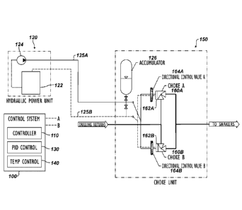
[0022] Fig. 2 illustrate features of a hydraulic power unit, a choke
manifold, and a
control system according to the present disclosure.
[0023] Fig. 3A illustrates a proportional-integral-derivative (PID) control
that can be
used in the control system.
[0024] Fig. 3B graphs the PID control of a choke showing the surface
backpressure
change relative to the controlled choke position.
[0025] Fig. 4 illustrates a schematic of the disclosed control system.
CA 03012457 2018-07-24
WO 2017/136185 PCT/US2017/014687
- 6 -
[0026] Fig. 5 illustrates a process according to the present disclosure to
account for
effects to choke response due to changes in temperature.
[0027] Fig. 6 illustrates a schematic of the disclosed control system to
account for
effects to choke response due to changes in temperature.
DETAILED DESCRIPTION OF THE DISCLOSURE
[0028] Systems and methods disclosed herein can be used to control one or
more
hydraulic chokes in a managed pressure drilling system. Although discussed in
this
context, the teachings of the present disclosure can apply equally to other
types of
controlled pressure drilling systems, such as other MPD systems (Pressurized
Mud-Cap
Drilling, Returns-Flow-Control Drilling, Dual Gradient Drilling, etc.) as well
as to
Underbalanced Drilling (UBD) systems, as will be appreciated by one skilled in
the art
having the benefit of the present disclosure.
[0029] Fig. 1 shows a closed-loop drilling system 10 according to the
present
disclosure for controlled pressure drilling. As shown and discussed herein,
this system
can be a Managed Pressure Drilling (MPD) system and, more particularly, a
Constant Bottomhole Pressure (CBHP) form of MPD system. Although discussed in
this context, the teachings of the present disclosure can apply equally to
other types of
controlled pressure drilling systems, such as other MPD systems (Pressurized
Mud-Cap
Drilling, Returns-Flow-Control Drilling, Dual Gradient Drilling, etc.) as well
as to
Underbalanced Drilling (UBD) systems, as will be appreciated by one skilled in
the art
having the benefit of the present disclosure.
[0030] One suitable example of a drilling system 10 is the Secure Drilling
TM System
available from Weatherford. Details related to such a system are disclosed in
U.S. Pat.
No. 7,044,237, which is incorporated herein by reference in its entirety.
[0031] The drilling system 10 has a rotating control device (RCD) 12 from
which a drill
string 14, a bottom hole assembly (BHA), and a drill bit 18 extend downhole in
a
wellbore 16 through a formation F. The rotating control device 12 can include
any
suitable pressure containment device that keeps the wellbore in a closed-loop
at all
times while the wellbore 16 is being drilled. The rotating control device
(RCD) 12 atop
the BOP contains and diverts annular drilling returns. It also completes the
circulating
system to create the closed loop of incompressible drilling fluid.
CA 03012457 2018-07-24
WO 2017/136185 PCT/US2017/014687
- 7 -
[0032] The system 10 also includes mud pumps 50, a standpipe (not shown), a
mud
tank 40, a mud gas separator 30, and various flow lines, as well as other
conventional
components. In addition to these, the drilling system 10 includes an automated
choke
manifold 150 that is incorporated into the other components of the system 10.
[0033] Finally, a control system 100 of the drilling system 10 is
centralized and
integrates hardware, software, and applications across the drilling system 10.
The
centralized control system 100 is used for monitoring, measuring, and
controlling
parameters in the drilling system 10. In this contained environment of the
closed-loop
drilling system 10, minute wellbore influxes or losses are detectable at the
surface, and
the control system 100 can further analyze pressure and flow data to detect
kicks,
losses, and other events.
[0034] The automated choke manifold 150 manages pressure and flow during
drilling
and is incorporated into the drilling system 10 downstream from the rotating
control
device 12 and upstream from the gas separator 30. The choke manifold 150 has
chokes 160A-B, a mass flow meter 24, pressure sensors, a local controller (not
shown)
to control operation of the manifold 150, and a hydraulic power unit 120 to
actuate the
chokes 160A-B. The control system 100 is communicatively coupled to the
manifold
150 and has a control panel with a user interface and processing capabilities
to monitor
and control the manifold 150.
[0035] As already noted above, the system 10 uses the rotating control
device 12 to
keep the well closed to atmospheric conditions. Fluid leaving the wellbore 16
flows
through the automated choke manifold 150, which measures return flow and
density
using the flow meter 24 installed in line with the chokes 160A-B. Software
components
of the control system 100 then compare the flow rate in and out of the
wellbore 16, the
injection pressure (or standpipe pressure), the surface backpressure (measured
upstream from the drilling chokes 160A-B), the position of the chokes 160A-B,
and the
mud density. Comparing these variables, the control system 100 identifies
minute
downhole influxes and losses on a real-time basis to manage the annulus
pressure
during drilling. All of the monitored information can be displayed for the
operator on the
control panel of the control system 100.
[0036] In the controlled pressure drilling, the control system 100
introduces pressure
and flow changes to this incompressible circuit of fluid at the surface to
change the
annular pressure profile in the wellbore 16. In particular, using the choke
manifold 150
CA 03012457 2018-07-24
WO 2017/136185 PCT/US2017/014687
- 8 -
to apply surface backpressure within the closed loop, the control system 100
can
produce a reciprocal change in bottom hole pressure. In this way, the control
system
100 uses real-time flow and pressure data and manipulates the annular
backpressure to
manage wellbore influxes and losses.
[0037] In the managed pressure drilling (MPD) system 10, the control system
100
monitors for any deviations in values during drilling operations, and alerts
the operators
of any problems that might be caused by a fluid influx into the wellbore 16
from the
formation F or a loss of drilling mud into the formation F. To do this, the
control system
100 monitors flow into the well for comparison to flow out of the well.
Therefore, a
pressure sensor and a means for measuring flow are provided for both "flow-in"
and
"flow-out" of the well 16. For the flow-in, the control system 100 can use the
pump
stroke counter to determine flow into the well and can use a pressure sensor
for the
stand pipe pressure (SPP). For the flow-out, the control system 100 can use
the
Coriolis flow meter 24 or the like on the choke manifold 150 to determine the
mass flow
out of the well 16 and can use a pressure sensor for the surface back pressure
(SBP). In other words, the system 100 uses sensors for mass flow and pressure
into
and out of the well 16. In this way, the control system 100 can automatically
detect,
control, and circulate out such influxes by operating the chokes 160A-B on the
choke
manifold 150.
[0038] For example, a possible fluid influx or "kick" can be noted when the
"flow out"
value (measured from the flow meter 24) deviates from the "flow in" value
(measured
from the stroke counters of the mud pumps 50). As is known, a "kick" is the
entry of
formation fluid into the wellbore 16 during drilling operations. The kick
occurs because
the pressure exerted by the column of drilling fluid is not great enough to
overcome the
pressure exerted by the fluids in the formation being drilled.
[0039] The kick or influx is detected when the well's flow-out is
significantly greater
than the flow-in for a specified period of time. Additionally, the standpipe
pressure
(SPP) should not increase beyond a defined maximum allowable SPP increase, and
the
density-out of fluid out of the well does not drop more than a surface gas
density
threshold. When an influx or kick is detected, an alert notifies the operator
to apply the
brake until it is confirmed safe to drill. Meanwhile, no change in the rate of
the mud
pumps 50 is needed at this stage.
CA 03012457 2018-07-24
WO 2017/136185 PCT/US2017/014687
- 9 -
[0040] In the control system 100, the kick control can be an automated
function that
combines kick detection and control, and the control system 100 can base its
kick
control algorithm on the modified drillers' method to manage kicks. In a form
of auto
kick control, for example, the control system 100 automatically closes the
chokes 160A-
B to increase surface backpressure in the wellbore annulus 16 until mass
balance is
established and the influx stops.
[0041] The system 100 adds a predefined amount of pressure as a buffer and
circulates the influx out of the well by controlling the stand pipe pressure.
The stand
pipe pressure will be maintained constant by automatically adjusting the
surface
backpressure, thereby increasing the downhole circulating pressure and
avoiding a
secondary influx.
[0042] Once the flow-out and flow-in difference is brought under control,
the control
system 100 will maintain this equilibrium for a specified time before
switching to the next
mode. In a successful operation, the kick detection and control cycle can be
expected
to be managed in roughly two minutes. The kick fluid will be moving up in the
annulus
with full pump speed using a small decreased relative flow rate of about -0.1
gallons per
minute to safely bring the formation pressure to balance.
[0043] On the other hand, a possible fluid loss can be noted when the "flow
in" value
(measured from the stroke counters of the pumps 50) is greater than the "flow
out"
value (measured by the flow meter 24). As is known, fluid loss is the loss of
whole
drilling fluid, slurry, or treatment fluid containing solid particles into the
formation matrix.
The resulting buildup of solid material or filter cake may be undesirable, as
may be any
penetration of filtrate through the formation, in addition to the sudden loss
of hydrostatic
pressure due to rapid loss of fluid.
[0044] Similar steps as those above, but suited for fluid loss, can then be
implemented
by the control system 100 to manage the pressure and flow during drilling in
this
situation. Killing the well is attempting to stop the well from flowing or
having the ability
to flow into the wellbore 16. Kill procedures typically involve circulating
reservoir fluids
out of the wellbore or pumping higher density mud into the wellbore 16, or
both.
[0045] In addition to the choke manifold 150, the drilling system 10 can
include a
continuous flow system (not shown), a gas evaluation device 26, a multi-phase
flow
meter 28, and other components incorporated into the components of the system
10.
The continuous flow system allows flow to be maintained while drillpipe
connections are
CA 03012457 2018-07-24
WO 2017/136185 PCT/US2017/014687
- 10 -
being made, and the drilling system 10 may or may not include such components.
For
its part, the gas evaluation device 26 can be used for evaluating fluids in
the drilling
mud, such as evaluating hydrocarbons and other gases or fluids of interest in
drilling
fluid. The multi-phase flow meter 28 can be installed in the flow line to
assist in
determining the make-up of the fluid.
[0046] As noted above, controlling pressure during drilling essentially
requires moving
the chokes 160A-B with a control to achieve a necessary amount of pressure or
flow
according to the purposes of the well control operations governed by the
control system
100. Therefore, an element of this automation is a control-loop feedback
mechanism
that consists of a control tailored to characterize the MPD equipment (e.g.,
choke
actuators) and is capable of adapting to changing dynamics, such as mud
systems, well
compressibility, drilling windows, and surface equipment limitations.
[0047] In the tight pore pressure and fracture gradient windows that can be
found in
wellbores 16, successful drilling often involves maintaining a predefined
pressure at a
specific depth in the well. This involves eliminating and minimizing pressure
spikes and
oscillations that might exceed the drilling window parameters and create a
kick-loss
event. Drilling under these circumstances commonly requires pressure regimes
that are
less than 100 psi between the respective gradients.
[0048] As noted above, hydraulic power is typically supplied remotely from
the
hydraulic power unit 120 to the chokes 160A-B of the system 10. As shown in
Fig. 2,
the hydraulic power unit 120 includes a hydraulic reservoir 122, one or more
hydraulic
pumps 124, and necessary piping, fittings and valves. These components can be
housed together on a skid or manifold. A supply line 125A from the pumps 124
communicates the hydraulic power to the choke manifold 150 positioned some
distance
away from the power unit 120. In a similar fashion, a return line 125B from
the choke
manifold 150 returns the hydraulics to the reservoir 122. Each choke 160A-B is
actuated by a hydraulic actuator 162A-B controlled by one of the directional
control
valves 164A-B connected either directly or remotely to the chokes 160A-B. The
independent directional control valves 164A-B are used to mitigate differences
in the
chokes 160A-B and provide independent feedback control of the chokes 160A-B.
[0049] In general, various types of control valves could be used for the
system's
valves 164A-B, and they can have various states for controlling the chokes
160A-B. For
example, the control valves 164A-B can have a first state directing the
hydraulic flow to
CA 03012457 2018-07-24
WO 2017/136185 PCT/US2017/014687
- 11 -
open the respective choke 160A-B, a second state directing the hydraulic flow
to close
the respective choke 160A-B, and a third state that closes off the hydraulic
flow to
neither open nor close the respective choke 160A-B. The control valves 164A-B
can be
operated by a solenoid or the like (not shown) with control signals from
control lines A
and B of the control system 100, as noted herein. In turn, the hydraulic power
directed
by the control valves 164A-B operates the respective hydraulic actuators 162A-
B for the
chokes 160A-B.
[0050] In another arrangement, two or more solenoid-operated directional
control
valves 164A-B with two or more valve positions can be connected either in
series or
parallel to achieve the three states mentioned above. In this way, the choke
open state,
closed state, and neither open nor closed state can be achieved with different
pairings
of positions between the two or more directional control valves.
[0051] As shown here in Fig. 2, the control valves 164A-B connected to the
supply and
return lines 125A-B may be directional and may typically have three states or
positions.
In a central state (when the solenoid is not activated), the directional
control valve 164A-
B allows for no flow in either direction. This closes all of the ports for
both of the supply
and return lines 125A-B so that there is no choke movement. A choke-opening or
parallel-flow state (when the solenoid is activated in one direction "A")
opens both ports
and allows flow from the supply line 125A into to Port A and allows flow out
of Port B to
the return line 125B. The choke 160A-B in turn is moved toward its open
direction.
Finally, a choke-closing or cross-flow state (when the solenoid is activated
in an
opposite direction "B") opens both ports but switches the direction of the
flow in each of
the ports for the supply and return lines 125A-B. The choke 160A-B in turn is
moved
toward its close direction.
[0052] Use of the hydraulic arrangement in Fig. 2 may improve the choke
responses
by reducing the differences in the hydraulic lines feeding the chokes 160A-B.
To help
further compensate for variations of temperature due to seasonal changes or
location/longitudinal changes, the unit 120 can use a hydraulic fluid with
lower viscosity
for use in colder climates and can use a different hydraulic fluid with higher
viscosity for
use in hotter climates. It may be possible to further reduce the effects of
temperature
and viscosity changes by using synthetic or other types of hydraulic fluid.
Although this
may generally acclimate the unit 120 for use in a general temperature range,
the control
system 100 preferably accounts for effects that finer temperature variations
have on the
CA 03012457 2018-07-24
WO 2017/136185 PCT/US2017/014687
- 12 -
choke response throughout the day as the hydraulic power unit 120 operates the
chokes 160A-B.
[0053] To help compensate for such finer variations in temperature, the
control system
100 uses one or more proportional-integral-derivative (PID) controls 130 that
compensate for finer variations in temperature. Additionally, the control
system 100
uses one or more temperature-based controls 140 to change the choke response
during
operations in response to changes in temperature.
[0054] At the start of an operation of the drilling system 10, for example,
the control
system 100 can be calibrated with initial PID controls 130 that are
appropriate for
operation. The PID controls 130 can be manually adjusted to get the best
control
response for the system 10. This adjustment may only be permitted once at the
beginning of the job due to the length of time it takes to find a sweet spot
for the PID
controls 130. Although proportional, integral, and derivative gains are
discussed, the
control 130 used in controlled pressure drilling is typically a proportion-
integral type of
control.
[0055] As noted above, the PID controls 130 control the chokes 160A-B to
change
pressure or flow in the system 10 in the controlled drilling operations by
providing the
feedback used to adjust and stabilize wellbore pressure and flow. Even though
initially
set, the PID controls 130 during normal operation of the system 100,will
eventually
cause the directional control valves 164A-B and actuators 162A-B to speed up
or slow
down the choke response while the chokes 160A-B obtain a pressure set point.
This
change is due in part from temperature changes in the hydraulic fluid, the
environment,
the manifold 150, hydraulic power unit 120, etc.
[0056] Accordingly, the control system 100 monitors the choke's response
(i.e.,
movement, speed, and accuracy) during operations so that the choke's response
can
be adjusted based on the temperature changes in the hydraulic fluid, the
environment,
the manifold 150, hydraulic power unit 120, etc.
[0057] When managed pressure drilling uses two or more chokes 160A-B in
simultaneous operation as shown, the temperatures can be different for the two
flow-
paths 125A-B depending on construction and the like. This can lead to a
different
system response between the chokes 160A-B. For example, one hydraulic choke
160A
may tend to respond more slowly than the other choke 160B. The control system
100
of the present disclosure can therefore be configured to operate the multiple
chokes
CA 03012457 2018-07-24
WO 2017/136185 PCT/US2017/014687
- 13 -160A-B in conjunction with one another while still accounting for
differences in their
responses due to temperature and the like.
[0058] Fig. 3A illustrates features of the proportional-integral-derivative
(PID) control
130 that can be used in the controlled pressure drilling to control a choke
160A-B. In
this PID control 130, a process variable 134 (e.g., current surface
backpressure in the
drilling system 10, current choke position, etc.) is compared to a configured
set point
132 to calculate an error 136. That error 136 can then be operated on by one
or more
of: a proportional gain (Kp) times the magnitude of the error (e(t)) (137p),
an integral
gain (Ki) times the integral of the error (e(t)) (137i), and a derivative gain
(Kd) times the
derivative of the error (e(t)) (137d). The one or more of these are then
summed
together to provide a controller output 138 (e.g., new pressure, new choke
position, etc.)
for adjusting a control value for hydraulic power unit 120, the directional
control valves
164A-B and/or the actuators 162A-B of the choke 160A-B.
[0059] In the drilling system 10, for example, the PID control 130
stabilizes wellbore
pressure fluctuations by managing pressure quickly in small increments. These
increments can be as small as 1 psi when circulating homogeneous fluid or
during pipe
connections with the aid of auxiliary flow, or as much as 10 psi when
circulating gas or
large cuttings. In other cases such as when tripping in or out with as much as
500-psi
of surface pressure, observed increments or decrements in pressure can range
from 5
to 20-psi.
[0060] Fig. 3B graphs how the PID control of choke position 80 functions to
control
surface backpressure 82. The choke position 80 is adjusted over time with the
PID
control 130 to affect the surface backpressure 82, which is graphed for
comparative
purposes. As it appears, the choke position 80 is adjusted closed as the
surface
backpressure continues to rise and reaches a peak level of almost 2000-psig. A
sudden drop in the surface backpressure 82 then follows, and the choke
position 80 is
rapidly adjusted open.
[0061] The control system 100 has various set points defined based on what
is
anticipated so that the choke position 80 can be controlled to achieve a
desired surface
backpressure 82. The PID control 130 for the chokes 160A-B in the manifold 150
are
configured to control the chokes 160A-B so the system 100 can reach the set
points.
Depending on temperature and other conditions, however, the existing PID
controls 130
CA 03012457 2018-07-24
WO 2017/136185 PCT/US2017/014687
- 14 -
may not adjust the chokes 160A-B as needed under certain circumstances for the
defined set point to be reached in an appropriate interval.
[0062] Accordingly, tuning for the various gains 137p, 137i, 137d of the
PID control
130 in Fig. 3A is handled to achieve a desired system response. As will be
appreciated,
all this handling and tuning of the PID control 130 depends on how the
operator sets up
the control system 100. Initially, the interface of the control system 100
requires that
certain parameters be established, such as set points, pressure and flow
differential
dead-bands, and time durations desired before the system reacts. According to
the
present disclosure, feedback of opening/closing speeds of the chokes 160A-B
during
operation is then used to tune/adjust the PID control 130 of the control
system 100.
Additionally, data related to temperature is used to tune/adjust the control
of the chokes
160A-B.
[0063] The control system 100 of the present disclosure, which performs the
tuning/adjustment, is schematically shown in Fig. 4. The control system 100
includes a
processing unit 102, which can be part of a computer system, a server, a
programmable
logic controller, etc. Using input/output interfaces 104, the processing unit
102 can
communicate with the choke(s) 160A-B and other system components to obtain and
send communication, sensor, actuator, and control signals 105 for the various
system
components as the case may be. In terms of the current controls discussed, the
signals
can include, but are not limited to, the choke position signals, the hydraulic
power unit
pressure signals, system pressure signals, system flow signals, temperature
signals,
fluid density signals, etc.
[0064] The processing unit 102 also communicatively couples to a database
or
storage 106 having set points 107, lookup tables 108, and other stored
information.
The lookup tables 108 characterize the specifications of the choke, flow
coefficient
character (e.g., flow coefficient versus choke position), and choke response
due to
temperature. This information can be defined by the choke's manufacture,
through
testing of the choke 160A-B, and through periodic calibration of the choke
160A-B.
Although lookup tables 108 can be used, it will be appreciated that any other
form of
curve, function, data set, etc. can be used to store the flow coefficient
character.
Additionally, multiple lookup tables 108 or the like can be stored and can be
characterized based on different chokes, different drilling fluids, different
operating
conditions, and other scenarios and arrangements.
CA 03012457 2018-07-24
WO 2017/136185 PCT/US2017/014687
- 15 -
[0065] Finally, the processing unit 102 can operate a choke controller 110
according to
the present disclosure for monitoring, tuning, and controlling the choke(s)
160A-B. For
example, the processing unit 102 can transmit signals to one or more of the
chokes
160A-B of the drilling system using any suitable communication. In general,
the signals
are indicative of a choke position or position adjustment to be applied to the
chokes
160A-B to achieve a desired set point in the MPD operations.
[0066] Typically, the chokes 160A-B are controlled by hydraulic power so
that
electronic signals transmitted by the processing unit 102 may operate
solenoids, valves,
or the like of a hydraulic power unit 120 for operating the chokes 160A-B. As
shown,
two chokes 160A-B are typically used in the closed-loop drilling system 10.
The same
choke control can apply adjustments to both chokes 160A-B or separate choke
controls
can be used for each choke 160A-B. In fact, the two chokes may have
differences that
can be accounted for in the two choke controls used.
[0067] As will be discussed in more detail below, the control system 100
uses the
high-speed choke controller 110 tuned in real-time using PID controls 130,
temperature
controls 140, among others. A choke position set point (107) is calculated in
real-time
and applied to a desired position for the choke(s) 160A-B to achieve the
purposes of the
controlled pressure drilling. In other words, the choke controller 110 uses
the PID
control 130 and the temperature-based control 140 for tuning/adjusting the
control and
determining the required adjustment to the current choke position to achieve
the desired
set point 107. This tuning/adjustment provides the required control response
as
conditions change and the choke 160A-B operates in its upper or lower ranges
of
temperature, which can improve performance of the choke manifold 150.
[0068] According to a first embodiment to tune/adjust the control of the
choke(s) 160A-
B, the control system 100 uses calculations based on the PID controls 130 to
handle the
disparate operations of the system 10 due to temperature changes over time.
Fig. 5
illustrates a process 200 performed by the control system 100 to handle
changes in
choke response due to temperature changes. In general, the control system 100
measures the choke position over time and calculates an accurate choke speed.
This
speed is then fed as an input for the control loop of the system 100 and
affects the
assigned PID variables of the PID control 130 controlling the directional
control valves
164A-B and actuators 162A-B for the choke manifold 150 and the hydraulic power
unit
120 if possible.
CA 03012457 2018-07-24
WO 2017/136185 PCT/US2017/014687
- 16 -
[0069] In particular, a number of opportunities may arise during a typical
operation that
would require the chokes 160A-B to be fully opened or closed. Therefore, the
control
system 100 can monitor for situations when the chokes 160A-B are to be opened
fully
or closed fully, such as when an operator manually instructs at a control
panel of the
system 100 for a choke to operate fully open or closed. Other situations may
also arise
in which the control system 100 automatically instructs the chokes 160A-B to
be opened
or closed fully. Whether user-initiated or automatic opening/closing of the
chokes 160A-
B is involved, the control system 100 can perform an ad hoc calibration of the
choke
response, which may be affected by current operating temperatures and the
like.
[0070] Looking at opening steps (Blocks 210-222) when the choke 160A-B
begins
opening toward full open (e.g., about 100% open), such as when manually or
automatically instructed open (Block 210), the directional control valve 164A-
B is left
wide open (i.e., in its "choke-opening or parallel-flow" state) (Block 212).
While the
valve 164A-B is left wide open, the control system 100 measures the time for
the choke
160A-B to reach at least a portion of a full open position (e.g.,
approximately 95% open)
(Block 214). A variance of a few percentages may be acceptable given an
implementation.
[0071] The current opening speed of the choke 160A-B is calculated based on
the
measured time for the choke 160A-B to move from its current position toward a
position
at least near full open (e.g., about 95% full open) (Block 216). The hydraulic
power unit
120 provides the hydraulic power through the open directional control valve
164A-B to
the actuator 162A-B of the choke 160A-B. The temperature of the hydraulic
fluid as well
as the components of the system may affect the choke response.
[0072] The current position of the choke 160A-B can be measured using a
sensor or
the like or may be determined mathematically. The final position at least near
open can
be comparably measured or determined. A timer in the control system 100 is
started at
the beginning of the operation and stops once the final near-open position is
reached.
Travel of the choke 160A-B from the current position to the final position is
determined,
and a simple calculation then determines the speed at which the choke 160A-B
opened
by dividing the determined travel by the timer's value.
[0073] The control system 100 compares the measured speed at this point in
the day's
operation to earlier measurements made during other points in the day (Block
218).
Based on the comparison (Block 218), the control system 100 adjusts the PID
variables
CA 03012457 2018-07-24
WO 2017/136185 PCT/US2017/014687
- 17 -
of the PID control 130 accordingly to keep the opening speed consistent
throughout
time (Block 222).
[0074] A preliminary determination can be made before adjusting the PID
variable to
ensure that the difference from the comparison is greater than a given
threshold
(Decision 220). This may prevent unnecessary changes in the system's
operation. In
the end, the control system 100 can automatically correct (or may prompt the
operator
for permission to correct) the PID values of the PID control 130 whenever the
choke
speed changes beyond a specified threshold (Block 222).
[0075] Selection of which gain (proportional, integral, or derivative) to
adjust and of
how much adjustment to make can be codified in the lookup tables 108 of the
control
system 100. The factors governing the selection can be determined from
historical and
experimental data and analysis.
[0076] The closing steps (Blocks 250-262) may use a reciprocal set of
operations
when the choke 160A-B begins closing toward full closed (i.e., about 0% open),
such as
when manually or automatically instructed closed (Block 250). The directional
control
valve 164A-B is held in its crossflow state to close the choke (Block 252).
While the
directional control valve 164A-B closes the choke 160A-B, the control system
100
measures the time for the choke 160A-B to reach at least a portion of a fully
closed
position (e.g., approximately 5% open) (Block 254). The current closing speed
of the
choke 160A-B is calculated based on the measurement of the time it takes the
choke
160A-B to move from its current position to the portion of the fully closed
position (Block
256). Then, the control system 100 compares the measured speed at this point
in the
day's operation to earlier measurements made during other points in the day
(Block
258). Based on the comparison, the control system 100 adjusts the PID
variables of the
PID control 130 accordingly to keep the closing speed consistent throughout
time (Block
262).
[0077] Portion of the fully closed choke 160A-B is used as a measurement
point
because the actual behavior of the choke beyond that point may be problematic.
In
general, the PID controls 130 may not work well when the choke 160A-B is near
its fully
closed states when small movements of the choke's components produces larger
changes in pressure or flow. Therefore, a portion or position near the fully
closed state
may be the preferred point at which to make the measurements. Similar reasons
can
apply to a portion or position near a fully open state of the choke 160A-B
because
CA 03012457 2018-07-24
WO 2017/136185 PCT/US2017/014687
- 18 -
opening beyond that position may have little appreciable difference. As an
option, a
pressure sensor (not shown) can be tied into the controller 110 to measure
changes in
pressure associated with the choke 160A-B.
[0078] Again, selection of the adjustments to the gains can be made in a
manner
similar to that noted above. Also, a preliminary determination can be made
before
adjusting the PID variable to ensure that the difference from the comparison
is greater
than a threshold (Decision 260). In the end, the control system 100 can
automatically
correct (or may prompt the operator for permission to correct) the PID values
whenever
the choke speed changes beyond a specified threshold (Block 262).
[0079] Because the choke manifold 150 as disclosed herein can have more
than one
choke 160A-B, each choke 160A-B can be separately assessed with these process
steps. In this way, the PID opening/closing values associated with the PID
control 130
for each choke 160A-B can be separately adjusted or not as needed. This is
useful
because the different chokes 160A-B may have differences that can be accounted
for
by separate controls.
[0080] The solution in Fig. 5 for choke position control can be implemented
mainly in
software and programming of the control system 100. No extra hardware may be
required in the system 100. In additional embodiment, a throttle valve 310 in
the HPU
120 can be used to improve choke position control. Also, a temperature sensor
and
other temperature features can be installed on the HPU 120 to provide
temperature
feedback as necessary.
[0081] As shown in Fig. 6, for example, the control system 100 can use a
temperature
sensor 300 to measure temperature information for improving control over the
choke
position while hydraulic fluid temperature changes. The sensor 300 can monitor
the
temperatures of the hydraulic fluid of the system 120. Feedback of the
temperature in
the control system 100 can then be used to tune/adjust the controls signals to
the
chokes 160A-B. As mentioned before, PID values can be fine-tuned to offer
improved
control and/or more consistent control for the system 10. With the addition of
a
hydraulic temperature feedback signal to the control system 100, an internal
calculation
can determine improved PID offset values for a given fluid temperature change.
[0082] As also shown in Fig. 6, the control system 100 can use an automated
control
throttle valve 310 (or valves as each choke could have its own throttle valve
to allow for
independent adjustment) in place of a manual needle valve inside the HPU 120.
The
CA 03012457 2018-07-24
WO 2017/136185 PCT/US2017/014687
- 19 -
valve 310 throttles the flow leading up to the chokes 160A-B. In operation,
the throttle
valve 310 is moved to a position that will allow the choke opening and closing
speeds to
be consistent throughout the range of fluid temperatures throughout the day.
Generally,
the throttle valve 310 can be electrically, pneumatically, or hydraulically
controlled.
[0083] Operation of the automated control throttle valve 310 is tied to
control feedback
of ambient temperature readings in the HPU reservoir 122, in the environment,
etc.,
such as provided by the temperature sensor 300. The fluid viscosity and
accumulator
pressure (which change based on temperature) may be calculated ahead of time,
and
the control loop may rely solely on temperature readings. Alternatively, the
HPU's
throttle control feedback can be tied to the choke position/time readings from
the control
system 100.
[0084] As further shown in Fig. 6, a heating element 320 may be added to
the HPU's
hydraulic reservoir 122 and/or accumulator bottle 126. Alternatively,
insulation 330 can
be added to surround the HPU 120, reservoir 122, accumulator bottle 126,
and/or other
related components. The temperature of the hydraulic fluid can be maintained
using a
combination of the heating and/or cooling systems 320 and insulation 330. The
insulation 330 can be added or taken away for seasonal and weather temperature
changes, and the heat supplied by the heating system 320 can likewise be
modulated.
[0085] As will be appreciated, teachings of the present disclosure can be
implemented
in digital electronic circuitry, computer hardware, computer firmware,
computer
software, or any combination thereof. Teachings of the present disclosure can
be
implemented in a computer program product tangibly embodied in a machine-
readable
storage device for execution by a programmable processor so that the
programmable
processor executing program instructions can perform functions of the present
disclosure. To that end, a programmable storage device having program
instructions
stored thereon for causing a programmable control device can perform the
teachings of
the present disclosure.
[0086] The teachings of the present disclosure can be implemented
advantageously in
one or more computer programs that are executable on a programmable system
including at least one programmable processor coupled to receive data and
instructions
from, and to transmit data and instructions to, a data storage system, at
least one input
device, and at least one output device. Storage devices suitable for tangibly
embodying
computer program instructions and data include all forms of non-volatile
memory,
CA 03012457 2018-07-24
WO 2017/136185 PCT/US2017/014687
- 20 -
including by way of example semiconductor memory devices, such as EPROM,
EEPROM, and flash memory devices; magnetic disks such as internal hard disks
and
removable disks; magneto-optical disks; and CD-ROM disks. Any of the foregoing
can
be supplemented by, or incorporated in, ASICs (application-specific integrated
circuits).
[0087] The foregoing description of preferred and other embodiments is not
intended
to limit or restrict the scope or applicability of the inventive concepts
conceived of by the
Applicants. It will be appreciated with the benefit of the present disclosure
that features
described above in accordance with any embodiment or aspect of the disclosed
subject
matter can be utilized, either alone or in combination, with any other
described feature,
in any other embodiment or aspect of the disclosed subject matter.
[0088] In exchange for disclosing the inventive concepts contained herein,
the
Applicants desire all patent rights afforded by the appended claims.
Therefore, it is
intended that the appended claims include all modifications and alterations to
the full
extent that they come within the scope of the following claims or the
equivalents thereof.