Note: Descriptions are shown in the official language in which they were submitted.
CA 03012755 2018-07-26
WO 2017/138993
PCT/US2016/062772
SLICING APPARATUSES AND METHODS FOR SLICING PRODUCTS
BACKGROUND OF THE INVENTION
[0001] The present
invention generally relates to methods and apparatuses for
slicing products. The invention particularly relates to machines having a
cutting
head equipped with at least one knife suitable for slicing products into
slices,
wherein the cutting head is configured to promote the stability of the
products during
slicing.
[0002] Various
types of equipment are known for slicing, shredding and
granulating food products, such as vegetable, fruit, dairy, and meat products.
A
widely used line of machines for this purpose is commercially available from
Urschel
Laboratories, Inc., under the name Urschel Model CC , an embodiment of which
is represented in FIG. 1. The Model CC machine line provides versions of
centrifugal-type slicers capable of producing uniform slices, strip cuts,
shreds and
granulations of a wide variety of products at high production capacities. When
used
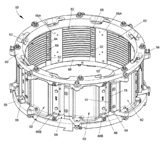
to produce potato slices for potato chips, the Model CC line of machines can
make
use of substantially round potatoes to produce the desired circular chip shape
with
a minimum amount of scrap.
[0003] The Model
CC machine 10 schematically represented in FIG. 1 includes
a cutting head 12 mounted on a support ring 15 above a gear box 16. A housing
18
contains a shaft coupled to the gear box 16 that rotates an impeller 14 within
the
cutting head 12 about an axis 17 of the cutting head 12. Products are
delivered to
the cutting head 12 and impeller 14 through a feed hopper 11 located above the
cutting head 12. In operation, the impeller 14 is coaxially mounted within the
cutting
head 12, which is generally annular-shaped with cutting knives (not shown)
mounted
- 1 -
CA 03012755 2018-07-26
CWCAS-510
at its perimeter. The impeller 14 rotates within the cutting head 12, while
the latter
remains stationary. The hopper 11 delivers products to the middle of the
impeller
14, and centrifugal forces cause the products to move outward into engagement
with the knives of the cutting head 12. Further descriptions pertaining to the
construction and operation of Model CC7 machines, including improved
embodiments thereof, are contained in U.S. Patent Nos. 5,694,824 and
6,968,765.
[0004] FIG. 2 is a perspective view of a cutting head 12 and FIGS. 3 and 4
are
perspective and cross-sectional views, respectively, of an impeller 14 of
types that
can be used in the Model CC7 machine of FIG. 1. Referring to FIG. 2, each
knife
13 of the cutting head 12 projects radially inward toward the interior of the
cutting
head 12, generally in a direction opposite the rotation of the impeller 14
within the
cutting head 12, and defines a cutting edge at its radially innermost
extremity. As
represented in FIGS. 3 and 4, the impeller 14 comprises generally radially-
oriented
paddles 28 disposed between a base 30 and an upper ring 32, the latter being
omitted in FIG. 4 to reveal the interior of the impeller 14 and orientations
of the
paddles 28. A frustoconical-shaped flange 34 extends in a generally axial
direction
from the ring 32 to define an opening 36 through which food products enter the
impeller 14. The paddles 28 have faces 38 that engage and direct the products
40
(e.g., potatoes) radially outward towards and against the knives 13 of the
cutting
head 12 as the impeller 14 rotates.
[0005] The cutting head 12 shown in FIG. 2 comprises a lower support ring
18,
an upper support ring 20, and circumferentially-spaced support segments
(shoes)
22. The knives 13 of the cutting head 12 are individually secured with
clamping
assemblies 26 to the shoes 22. Each clamping assembly 26 includes a knife
holder
26A mounted to the radially inward-facing side of a shoe 22, and a clamp 26B
- 2
CA 03012755 2018-07-26
WO 2017/138993
PCT/US2016/062772
mounted on the radially outward-facing side of a shoe 22 to secure the knife
13 to
the knife holder 26A. The shoes 22 are represented as secured with bolts 25 to
the
support rings 18 and 20. The shoes 22 are equipped with coaxial pivot pins
(not
shown) that engage holes in the support rings 18 and 20. By pivoting on its
pins,
the orientation of a shoe 22 can be adjusted to alter the radial location of
the cutting
edge of its knife 13 with respect to the axis of the cutting head 12, thereby
controlling the thickness of the sliced product. As an example, adjustment can
be
achieved with an adjusting screw and/or pin 24 located circumferentially
behind the
pivot pins. FIG. 2 further shows optional gate inserts 23 mounted to each shoe
22,
which the product crosses prior to encountering the knife 13 mounted to the
trailing
shoe 22. Each gate insert 23 and its corresponding knife 13 define a gate
opening
whose width can be adjusted by pivoting the shoe 22 toward and away from the
cutting edge of the knife casing 40. As such, the thickness of each slice
produced
by a knife 13 is determined by the gate opening, and specifically the radial
distance
between the cutting edge of a knife 13 and the adjacent trailing edge of a
gate insert
23. As used herein, "trailing" refers to a position on a cutting head that
follows or
succeeds another in the direction of rotation of an impeller assembled with
the
cutting head, whereas "leading" refers to a position on a cutting head that is
ahead
of or precedes another in the direction opposite the impeller's rotation.
[0006] The knives
13 shown in FIG. 2 are depicted as having straight cutting
edges for producing flat slices, though knives of other shapes can be
installed in
Model CC machines to produce sliced, strip-cut, shredded and granulated
products. A nonlimiting example is knives having cutting edges that define a
periodic pattern of peaks and valleys when viewed edgewise. The periodic
pattern
can be characterized by sharp peaks and valleys, or a more corrugated or
sinusoidal
shape characterized by more rounded peaks and valleys when viewed edgewise.
If the peaks and valleys of each knife are aligned with those of the immediate
- 3 -
CA 03012755 2018-07-26
WO 2017/138993
PCT/US2016/062772
leading knife, slices are produced in which each peak on one surface of a
slice
corresponds to a valley on the opposite surface of the slice, such that the
slices can
be substantially uniform in thickness but have a cross-sectional shape that is
characterized by sharp peaks and valleys ("V-slices") or a more corrugated or
sinusoidal shape (crinkle slices), collectively referred to herein as periodic
shapes.
Alternatively, shredded product can be produced if each peak of each knife is
aligned with a valley of the immediate leading knife, and waffle/lattice-cut
product
can be produced by intentionally making off-axis alignment cuts with a
periodic-
shaped knife, for example, by crosscutting a product at two different angles,
typically
ninety degrees apart. In addition, strip-cut and granulated products can be
produced with the use of additional knives and/or cutting wheels located
downstream of the knives. Whether a sliced, strip-cut, shredded, granulated,
or
waffle-cut product is desired will depend on the intended use of the product.
[0007] Though flat
gate inserts are commonly used for a variety of slicing
applications, the gate inserts 23 represented in FIG. 2 have ribs that define
raised
edges to create a row of openings that precede each knife 13 and through which
rocks, sand, and other debris can exit the cutting head 12 without damaging
the
knives 13 and knife holders 26A. As taught in U.S. Patent Application
Publication
No. 2014/0007751, to promote phase alignment of potato chips having
large-amplitude corrugations, large-amplitude corrugated shoes and gate
inserts
may be used in combination with large-amplitude corrugated knives for the
purpose
of maintaining product alignment during slicing.
[0008] Model CC
machines such as represented in FIGS. 1-4 are well suited
for producing slices from a wide variety of food products. Even so, certain
operating
conditions can impact the ability of these machines to produce slices of
uniform
thickness at high production capacities. For example, FIG. 5 schematically
- 4 -
CA 03012755 2018-07-26
WO 2017/138993
PCT/US2016/062772
represents four shoe sections of the cutting head of FIG. 2 and a condition
that may
occur that can lead to variability in thicknesses of slices 42 produced during
a slicing
operation. Water is commonly used as a lubricating fluid in food processing
equipment, and a hydroplaning effect occurs to some degree between the
products
40 (represented as potatoes) and the shoes 22 and gate inserts 23 prior to and
during the slicing operation. Ordinarily, some degree of hydroplaning is
desirable,
consistent with the intent that the water serves as a lubricant between the
products
40 and the interior surfaces of the shoes 22 and gate inserts 23. However,
there is
a growing trend to recycle water used in such equipment to conserve water and
promote the environmental friendliness of the process by reducing the amount
of
waste water produced. Particularly when slicing potatoes and other starchy
food
products, the result is that the water may contain a significant amount of
starch
solids that increase the viscosity of the water and may also behave as an
abrasive
on the surfaces of the shoes 22 and gate inserts 23. FIG. 5 represents a
relatively
thick water film 44 present between the products 40 and cutting head 12 and,
notably, between the products 40 and the ribs 46 of the gate inserts 23 as
more
readily apparent from the detailed image in FIG. 5. Such a film 44 can lead to
sufficient hydroplaning to cause instability of the products 40 while in
contact with
the shoes 22 and inserts 23, which can result in variability in the
thicknesses of the
slices 42. Though such slice variability may be very slight, it may be
sufficient to
impact the desired uniformity of certain products, for example, fried or baked
potato
chips, as a result of the possibility of over-cooked and/or under-cooked
regions
within individual chips.
BRIEF DESCRIPTION OF THE INVENTION
[0009] The present
invention provides apparatuses and methods suitable for
slicing products.
- 5 -
CA 03012755 2018-07-26
WO 2017/138993
PCT/US2016/062772
[0010] According
to one aspect of the invention, an apparatus for slicing products
has an annular-shaped cutting head comprising an axis defining an axial
direction,
knife assemblies located at a circumference of the cutting head, and arcuate
interior
surfaces each located in a first circumferential direction of the cutting head
relative
to a corresponding one of the knife assemblies such that each of the interior
surfaces leads one of the knife assemblies and trails a different one of the
knife
assemblies. Each knife assembly comprises a flat knife and means for securing
the
knife to the cutting head. Each knife extends radially inward and in the first
circumferential direction to define a gate opening and produce product slices
with
parallel cuts and a uniform thickness. Each of the interior surfaces has a
plurality
of continuous flow paths defined therein that extend across at least a
majority of the
interior surface from adjacent a leading edge thereof through a trailing edge
thereof
and are fluidically connected to one of the gate openings between the interior
surface and the knife that trails the interior surface.
[0011] According
to another aspect of the invention, the apparatus further
comprising an impeller coaxially mounted within the cutting head for rotation
about
the axis of the cutting head in a direction opposite the first circumferential
direction
of the cutting head. A method of using such an apparatus may comprise rotating
the impeller, supplying a lubricating fluid to the impeller, supplying
products to the
impeller that are delivered radially outward toward the cutting head, and
slicing the
products with the knives of the cutting head to produce product slices with
parallel
cuts and a uniform thickness.
[0012] Other
aspects of the invention include recycling the lubricating fluid
through the cutting head, and the presence of starch solids in the lubricating
fluid as
a result of the products being starchy food products, for example, potatoes.
- 6 -
CA 03012755 2018-07-26
WO 2017/138993
PCT/US2016/062772
[0013] Technical
effects of apparatuses and methods described above preferably
include the ability to reduce slice variability by reducing the thickness of a
lubricant
film on the surfaces of the shoes and gate inserts, particularly if the
lubricant
contains recycled water and the product is a starchy food product.
[0014] Other
aspects and advantages of this invention will be better appreciated
from the following detailed description.
BRIEF DESCRIPTION OF THE DRAWINGS
[0015] FIG. 1 is a
side view in partial cross-section representing a slicing
machine known in the art.
[0016] FIG. 2 is a
perspective view representing a cutting head of a type suitable
for use with the slicing machine of FIG. 1.
[0017] FIG. 3 is a
perspective view representing an impeller of a type suitable for
use with the slicing machine of FIG. 1 and cutting head of FIG. 2.
[0018] FIG. 4 is a
cross-sectional view of the impeller of FIG. 3 indicating its
rotation by which products are forced radially outward toward, for example,
the
cutting head of FIG. 2.
[0019] FIG. 5
schematically represents an operating condition that can occur with
the machine, cutting head and impeller represented in FIGS. 1 through 4.
[0020] FIG. 6 is a
perspective view representing a cutting head in accordance
with a non limiting embodiment of the invention and suitable for use in the
slicing
- 7 -
CWCAS-510
machine of FIG. 1 and with the impeller of FIGS. 3 and 4.
[0021] FIG. 7 represents a portion of the cutting head of FIG. 6 showing in
more
detail a shoe and gate insert of the cutting head.
[0022] FIG. 8 is an isolated view of one of the shoes of the cutting head
of FIGS.
6 and 7.
[0023] FIG. 9 is a detailed view of a portion of a cutting head similar to
FIGS. 6
and 7, but with an alternative configuration for the gate insert.
[0024] FIG. 10 schematically represents an operating condition of a cutting
head
equipped with shoes of FIGS. 6 through 9 and the gate insert of FIG. 9.
[0025] FIGS. 11A through 11D and 12A through 12B are isolated views of
alternative configurations for shoes suitable for use with the cutting head of
FIG. 6
and the gate inserts of FIGS. 6 through 9.
DETAILED DESCRIPTION OF THE INVENTION
[0026] The present invention provides slicing apparatuses and methods
capable
of producing a variety of sliced food products, including chips from potatoes,
and to
sliced products produced therewith. Although the invention will be described
herein
as slicing food product, it is foreseeable that the slicing apparatuses and
methods
may be used for slicing other food products and non-food materials, and
therefore
the scope of the invention should not be limited to any particular products.
The
slicing apparatuses are preferably adapted to cut food products into slices
with
generally parallel cuts resulting in food product slices of uniform thickness.
- 8 -
Date Recue/Date Received 2020-05-20
CA 03012755 2018-07-26
WO 2017/138993
PCT/US2016/062772
[0027] FIGS. 6 and
7 show a cutting head 50 in accordance with a nonlimiting
embodiment of the present invention. The cutting head 50 is configured for use
in
a slicing machine, as a nonlimiting example, the centrifugal-type slicing
machine 10
represented in FIG. 1, and in combination with an impeller, as a nonlimiting
example, the impeller 14 represented in FIGS. 1, 3 and 4, in which case the
impeller
14 is mounted within the cutting head 50 for rotation about the axis of the
cutting
head 50. However, other configurations of impellers adapted for installation
and
rotation in an annular-shaped cutting head could be used as discussed above in
reference to FIGS. 1 through 4. Accordingly, though the cutting head 50 will
be
discussed below in reference to the impeller 14 of FIGS. 1, 3 and 4, it should
be
understood that the cutting head 50 can find suitable use with impellers other
than
what is shown in the drawings.
[0028] The cutting
head 50 is represented in FIGS. 6 and 7 as having an annular
shape with multiple knife assemblies arranged and spaced around the
circumference of the cutting head 50. Each knife assembly includes a knife 52
and
means for securing the knife 52 to the cutting head 50. In the nonlimiting
embodiment shown in FIGS. 5 and 6, the securing means includes clamping
assemblies 66, each including a knife holder 66A mounted to the radially
inward-
facing side of one of a number of circumferentially-spaced shoes (support
segments) 62, and a clamp 66B mounted on the radially outward-facing side of
the
same shoe 62 to secure a knife 52 to the knife holder 66A. Each knife 52 is
mounted to extend in a radially inward direction of the cutting head 50, so as
to
project toward an impeller that would be mounted for rotation within the
cutting head
50 (for example, as represented by the impeller 14 in FIG. 1). Each knife 52
has a
cutting edge that terminates at a knife tip. The knives 52 shown in FIGS. 6
and 7
are depicted as "flat" knives, which as used herein means that the cutting
edges of
the knives 52 are straight to produce flat slices.
- 9 -
CA 03012755 2018-07-26
WO 2017/138993
PCT/US2016/062772
[0029] Each shoe
62 is mounted between lower and upper support rings 58 and
60, to which the shoe 62 is pivotally coupled so that its orientation can be
adjusted
to alter the radial location of the cutting edge of its knife 52 with respect
to the axis
of the cutting head 50, thereby controlling the thickness of a sliced product
produced
with the knife 52. As an example, adjustment can be achieved with an adjusting
screw and/or pin 54 located circumferentially behind the pivot axis of the
shoe 62.
FIGS. 6 and 7 further show gate inserts 68 mounted circumferentially behind
(trailing) a trailing edge 82 of each shoe 62. Each insert 68 is preferably
directly
secured to its corresponding shoe 62, for example, with fasteners 64A
assembled
within bores 64B (FIG. 8A) provided in a trailing flange 63 of the shoe 62.
Consistent with the annular shape of the cutting head 50, interior surfaces of
each
shoe 62 and insert 68 have arcuate shapes. An impeller mounted for rotation
within
the cutting head 50 (while the latter remains stationary) causes products
delivered
thereto (for example, with a hopper of a type represented in FIG. 1) to move
outward
under centrifugal forces and engage the knives 52 of the cutting head 12. In
so
doing, the products contact and move across an interior surface 65 of a shoe
62 and
an interior surface of gate insert 68 prior to encountering one of the knives
52
mounted to an immediately trailing shoe 62. The gate inserts 68 are the last
surfaces contacted by products prior to engaging the knives 52, and the
trailing
edge 84 of each gate insert 68 (FIG. 7) and the immediately trailing knife 52
define
a gate opening 78 that determines the thickness of a slice produced by the
knife 52.
The width of the gate opening 78 is adjusted by pivoting the leading shoe 62
toward
and away from the cutting edge of the trailing knife 52 to alter the radial
distance
between the cutting edge of a knife 52 and the adjacent trailing edge 84 of
the gate
insert 68.
[0030] The gate
inserts 68 represented in FIGS. 6 and 7 are similar to the gate
inserts 23 represented in FIG. 2, in that each insert 68 has ribs 70 that
define raised
-10-
CA 03012755 2018-07-26
WO 2017/138993
PCT/US2016/062772
edges to create a row of channels 72 that are separated from each other by one
of
the ribs 70. The channels 72 define a row of openings that precede the
immediately
trailing knife 52 and through which rocks, sand, and other debris can exit the
cutting
head 50 without damaging the knives 52 and knife holders 66A. FIGS. 6 and 7
further represent the shoes 62 as having channels 74 recessed into their
interior
surfaces 65. According to one aspect of the invention, the channels 72 and 74
of
the inserts 68 and shoes 62 are "aligned channels," which as used herein means
the
channels 72 and 74 are parallel to each other and perpendicular to the axis of
the
cutting head 50 and to the axis of an impeller mounted for rotation within the
cutting
head 50, such that the channels 72 and 74 are aligned with the direction that
products travel across the interior surfaces 65 of the shoes 62 and across the
interior surfaces of the inserts 68. According to a preferred aspect of the
invention,
each channel 74 of a shoe 62 is individually aligned with one of the channels
72 of
its trailing gate insert 68 to create a continuous flow path from the leading
edge 80
of the shoe 62 adjacent the immediately leading knife holder 66A to the gate
opening 78 defined between the trailing edge 84 of the insert 68 and its
immediately
trailing knife 52. Positive and precise alignment of the channels 72 and 74
can be
achieved and maintained as a result of each insert 68 being directly secured
to its
corresponding shoe 62, as discussed above.
[0031] The aligned
channels 74 in the shoes 62 shown in FIGS. 6 and 7 have
smaller cross-sectional areas than the aligned channels 72 formed by the gate
inserts 68 as a result of being narrower and shallower than the aligned
channels 72.
As more readily seen in FIGS. 8A and 8B, the aligned channels 74 of the shoes
62
have U-shaped cross-sections, for example, a cross-section that is
semicircular or
a circular segment, and therefore differ in cross-sectional shape from the
rectangular-shaped cross-sections of the aligned channels 72 of the gate
inserts 68.
Suitable depths and widths for the channels 74 are believed to be in a range
of
-11-
CA 03012755 2018-07-26
WO 2017/138993
PCT/US2016/062772
about 0.75 to 2.5 mm, with the widths of the channels 74 typically being
greater than
their depths, though shallower, deeper, narrower, and wider channels 74 are
foreseeable. By fabricating the aligned channels 74 to have sufficiently large
cross-
sectional areas, the aligned channels 72 and 74 are able to reduce
hydroplaning of
products contacting the shoes 62 prior to and during the slicing operation
when
water (or another liquid) is used as a lubricating fluid.
[0032] As also
apparent from FIGS. 8A and 8B, surfaces 76 of the shoes 62
between the aligned channels 74 are "flat," which in the sense of the arcuate
shapes
of the shoes 62 means that, though the surfaces 76 appear arcuate when viewed
in a direction parallel to the axis of the cutting head 50, the surfaces 76
are collinear
when viewed in cross-section along a section parallel to the axis of the
cutting head
50, as seen in the surface geometry (profile) of FIG. 8B. As such, products
engaging the interior surfaces 65 of the shoes 62 do not contact a raised
feature,
such as peaks of a corrugated surface intended to maintain product alignment
during slicing. Instead, the continuous flow paths formed by the aligned
channels
72 and 74 are recessed below the surfaces 76 of the shoes 62, and products
engaging the interior surfaces 65 of the shoes 62 are supported by what is
defined
herein as "flat" surfaces 76 (when viewed as a cross-section parallel to the
axis of
the cutting wheel 50). In addition, the surfaces 76 of the shoes 62 are
significantly
wider (in the axial direction of the cutting head 50) than the aligned
channels 74.
For example, FIG. 8B represents a width ratio of greater than 2:1 and
approaching
4:1, in other words, the surfaces 76 in the embodiment of FIGS. 8A and 8B
account
for greater than 50% and up to about 75% of the surface 65 of each shoe 62.
[0033] From the
foregoing, it can be appreciated that in combination the shoes
62 and gate inserts 68 define interior surfaces of the cutting head 50, and
each such
interior surface leads the knife 52 of a trailing knife assembly and trails
the knife 52
-12-
CA 03012755 2018-07-26
WO 2017/138993
PCT/US2016/062772
of a leading knife assembly. In FIGS. 6, 7, 8A and 8B, the continuous flow
paths
defined by the aligned channels 72 and 74 of the shoes 62 and gate inserts 68
extend from the leading edge 80 of the shoe 62 to the trailing edge 84 of the
gate
insert 68 in order to be fluidically connected to the trailing gate opening
78.
However, it is foreseeable that acceptable results could be obtained as long
as the
leading ends of the continuous flow paths are sufficiently close (adjacent) to
the
leading edge 80 of the shoe 62, for example, by extending across the majority
of the
interior surface 65 of the shoe 62. In some embodiments, the gate inserts 68
may
be omitted, in which case the flange 63 could also be omitted and the interior
surfaces 65 of the shoes 62 (i.e., between the leading and trailing edges 80
and 82
of each shoe 62; FIG. 7) would define the entirety of the interior surfaces of
the
cutting head 50 between the knife assemblies.
[0034] The effect
on hydroplaning noted above is schematically represented in
FIG. 10 in reference to a cutting head 150 represented in FIG. 9 as identical
to the
cutting head 50 of FIGS. 6 and 7 except for gate inserts 168 that differ from
those
of FIGS. 6 and 7 by having an interior surface with aligned channels 172 whose
cross-sectional shape are U-shaped (for example, a cross-section that is
semicircular or a circular segment), and more nearly match that of the aligned
channels 74 in the shoes 62. In other words, the surface geometry of the
aligned
channels 172 is essentially identical to the surface geometry shown in FIG.
8B, and
surfaces 170 of the inserts 168 between the aligned channels 172 are flat and
collinear when viewed in cross-section along a section parallel to the axis of
the
cutting head 150. As such, products engaging the interior surfaces of the
inserts
168 do not contact raised features such as the raised edges of the ribs 70
shown
in FIGS. 6 and 7. Instead, the aligned channels 74 and 172 are recessed below
the
surfaces 76 and 170 of the shoes 62 and gate inserts 168, again creating
continuous flow paths that extend from the leading edges 80 of the shoes 62 to
the
-13-
CA 03012755 2018-07-26
WO 2017/138993
PCT/US2016/062772
trailing edges 184 of the inserts 168 to reduce hydroplaning of products
contacting
the inserts 168 and shoes 62 prior to and during the slicing operation. The
depth
and width of each channel 172 are preferably at least equal to, respectively,
the
depth and width of the channel 74 with which it is aligned, and in certain
embodiments are greater than the depth and width of the aligned channel 74,
for
example, in a range of about 1 to 3 mm, with the result that the aligned
channels 74
in the shoes 62 have smaller cross-sectional areas than the aligned channels
172
of the gate inserts 168. The widths of the channels 172 are typically greater
than
their depths, though shallower, deeper, narrower, and wider channels 172 are
foreseeable.
[0035] In FIG. 10,
four shoe sections of the cutting head 150 of FIG. 9 are
schematically represented. A rotating impeller within the cutting head 150 is
omitted
for clarity, but it should be understood that an impeller is present, a
lubricating fluid
and products 40 are supplied to the impeller, and the products 40 are
delivered
radially outward toward the cutting head 150 to undergo slicing with knives 52
to
produce product slices 142 of uniform thickness. FIG. 10 also illustrates that
some
degree of hydroplaning is present, consistent with the intent that water (or
another
fluid) serves as a lubricant between the products 40 and the interior surfaces
of the
shoes 62 and gate inserts 168. However, FIG. 10 schematically represents that
a
much thinner water film 144 is present between the products 40 and cutting
head
150, as apparent from the detailed image in FIG. 10. Though the film 144
between
the products 40 and the surfaces 170 of the gate inserts 168 is most readily
seen
in FIG. 10, the film 144 is also present between the products 40 and the
surfaces
76 of the shoes 62 and the thickness of the film 144 may be similar between
the
leading edges 80 of the shoes 62 and the trailing edges 184 of the inserts 168
due
to the similar surface geometries of the shoes 62 and inserts 168. The thinner
film
144 is the result of the presence of the continuous flow paths formed by the
aligned
- 14 -
CA 03012755 2018-07-26
WO 2017/138993
PCT/US2016/062772
channels 74 and 172 recessed below the surfaces 76 and 170 of the shoes 62 and
gate inserts 168. The aligned channels 74 and 172 drain water from the film
144 on
the surfaces 76 and 170 and conduct the water toward the gate opening 178
between the insert 168 and its trailing knife 52.
[0036] By reducing
the thickness of the film 144, hydroplaning can be reduced
to promote stability of the products 40 while in contact with the shoes 62 and
inserts
168, thereby reducing variability in the thicknesses of the slices 142 and
promoting
uniformity of products produced from the slices 142, for example, fried or
baked
potato chips that may have over-cooked and/or under-cooked regions within
individual chips if the slices 142 were not sufficiently uniform in thickness.
The effect
of the continuous flow paths formed by the aligned channels 74 and 172 is
especially beneficial under conditions in which water used in the slicing
operation
contains a significant amount of starch solids as a result of being recycled
to
conserve water and promote the environmental friendliness of the process by
reducing the amount of waste water produced. Starch solids content can be a
particular issue if slicing potatoes or another starchy food product, leading
to
increased viscosity of the water and abrasion of the surfaces of the shoes 62
and
gate inserts 168.
[0037] To achieve
consistently well-defined surface geometries and alignment
with the channels 72/172 formed in the gate inserts 68/168, the U-shaped
aligned
channels 74 represented in FIGS. 6-10 are preferably machined in the interior
surface 65 of the shoe 62, though otherfabrication techniques are foreseeable.
The
shoes 62 represented in FIGS. 6-10 have fifteen U-shaped channels 74, thirteen
of
which are aligned with thirteen U-shaped or rectangular channels 72/172 of the
gate
inserts 68/168 to create thirteen continuous flow paths between the
immediately
leading knife holder 66A and the gate opening 78/178 with the immediately
trailing
-15-
CA 03012755 2018-07-26
WO 2017/138993
PCT/US2016/062772
knife 52. The two excess aligned channels 74 of the shoes 62 are located at
opposite ends of the row of parallel channels 74 on each shoe 62 and can
deliver
water above and below the corresponding inserts 68/168.
[0038] According
to additional aspects of the invention, the surface geometries
of shoes and gate inserts installed in a cutting head can differ from those
shown in
FIGS. 6 through 10. As a nonlimiting example, FIG. 11A represents a shoe 262
in
whose interior surface 265 twenty-two U-shaped aligned channels 274 have been
formed and extend from the leading edge 280 to the trailing edge 282 of the
shoe
262. Each aligned channel 274 may be aligned with one of an equal number of
aligned channels (e.g., 72 or 172) of an insert (e.g., 68 or 168) or more than
one
channel 274 may be aligned with each channel 72/172 of an insert 68/168 to
create
continuous flow paths that extend from the leading edge 280 of the shoe 262 to
the
trailing edge 84/184 of the gate insert 68/168.
[0039] FIGS. 11B,
11C and 11D depict three different shoes 362, 462, and 562
that do not have aligned channels (as defined herein), but instead have random
continuous flow paths as a result of the manner in which channels are formed
in
their interior surfaces 365, 465 and 565, respectively. In particular, FIG.
11B
represents the interior surface 365 of the shoe 362 as having been grit
blasted to
create random interconnected channels 374 that extend from the leading edge
380
to the trailing edge 382 of the shoe 362, FIG. 11C represents the interior
surface
465 of the shoe 462 as having been sanded with a relatively coarse grit (e.g.,
CAMI
60) to create random interconnected channels 474 that extend from the leading
edge 480 to the trailing edge 482 of the shoe 462, and FIG. 11D represents the
interior surface 565 of the shoe 562 as having been sanded with a finer grit
(e.g.,
CAMI 80) to create random interconnected channels 574 that extend from the
leading edge 580 to the trailing edge 582 of the shoe 562. The sanding
processes
-16-
CA 03012755 2018-07-26
WO 2017/138993
PCT/US2016/062772
used to produce the channels 474 and 574 may result in the channels 474 and
574
being somewhat less random than the channels 374 formed by grit blasting, and
to
some degree aligned as indicated by FIGS. 110 and 11D. In each case, the
random channels 374, 474, and 574 must be sufficiently deep and interconnected
to create continuous flow paths across their respective surfaces 365, 465, and
565.
In investigations leading to the present invention, shoes 62 and 262 with
aligned
channels 74 and 274 were shown to be more effective in reducing hydroplaning
than
shoes 362, 462, and 562 with random channels 374, 474, and 574.
[0040] FIGS. 12A
and 12B depict two different shoes 662 and 762 that have
aligned channels 674 and 774 (as defined herein) that extend between the
respective leading edges 680 or 780 and trailing edge 682 or 782 of the shoes
662
and 762, but are fabricated to have surfaces 676 and 776 between the channels
674
and 774 that differ from the surfaces 76 represented in FIGS. 6-10. In
particular,
though the channels 674 and 774 have U-shaped cross-sectional shapes, the
surfaces 676 and 776 therebetween are not collinear when viewed in cross-
section
along a section parallel to the axis of the cutting head 50, as evident from
the
surface geometries (profiles) shown in FIGS. 12A and 12B. The surface
geometries
represented in FIGS. 12A and 12B can be created by machining shoes 662 and 762
whose interior surfaces 665 and 765 have a corrugated or V-shaped waveform.
FIG. 12A represents the channels 674 as being machined in the valleys of a
shoe
662 whose interior surface 665 has a corrugated or sinusoidal shape
characterized
by rounded peaks and valleys when viewed edgewise, such that the surfaces 676
between channels 674 are defined by rounded peaks. FIG. 12B represents the
channels 774 as being machined in the valleys of a shoe 762 whose interior
surface
765 is defined by sharp peaks and valleys, such that the surfaces 776 between
channels 774 are defined by sharp peaks. Knives having these periodic
waveforms
(minus the channels 674 and 774) are known in the art for producing sliced
products
-17-
CA 03012755 2018-07-26
WO 2017/138993
PCT/US2016/062772
often referred to as V-slices and crinkle slices.
[0041] While the
invention has been described in terms of specific embodiments,
it is apparent that other forms could be adopted by one skilled in the art.
For
example, shoes and gate inserts suitable for use therewith could differ in
appearance and construction from the embodiments shown in the drawings, the
cutting heads and impellers and the functions of their components could be
performed by components of different construction but capable of a similar
(though
not necessarily equivalent) function, and various materials and processes
could be
used to fabricate the shoes and gate inserts. Therefore, the scope of the
invention
is to be limited only by the following claims.
-18-