Note: Descriptions are shown in the official language in which they were submitted.
CA 03012872 2018-07-26
WO 2017/156339 PCT/US2017/021681
LOW-FREQUENCY DAS SNR IMPROVEMENT
FIELD OF THE DISCLOSURE
[0001] The disclosure relates to well logging techniques used in oil and
gas recovery
operations. In particular, a workflow utilizing methods of improving signal-to-
noise ratio and
decreasing interferences for Low-Frequency Distributed Acoustic Sensing is
described.
BACKGROUND OF THE DISCLOSURE
[0002] For hydrocarbon recovery, accurate production monitoring of the
pathways
between the wellbore and the reservoir are required for the economic
optimization of the
techniques and procedures used to complete wells. In the development of oil
and gas and other
similar wells, it is often necessary to utilize well logging surveys to
determine the fraction of oil,
gas and unwanted water present in the production zone. This data, along with
measurements of the
fluid flow velocity, porosity, cross-section of the well, pressure and
temperature, may be used to
determine production rates and other information from each zone of interest in
the well. Such data
may be useful for optimizing the well's production, oil recovery, water shut-
off and/or fracturing
sequence, in order to achieve better reservoir management and to reduce
intervention costs.
[0003] Well logging surveys are performed using logging tools that
generally comprise at
least one sensor and measure at least one parameter. Logging tools have
included spinner type
flow meters with attached temperature sensors, which rotate when immersed
within a flow stream.
However, this type of logging tool has had issues with mechanical
effectiveness. For example, the
impeller of the spinner operates on a bearing, which wears and requires
frequent inspection and
replacement to keep frictional effects from influencing the measurements.
Another disadvantage,
which increases logging time on the well, is that calibration must be done
downhole by making
several extra logging runs at various logging speeds. In reference to the
fluid properties, the spinner
speed is not only affected by changes in the velocity of the fluid, but also
by changes in the
viscosity and density of the fluid.
[0004] Optical fibers have been used in a variety of logging tools. One
technique for
substantially instantaneous measurement is fiber optic Distributed Temperature
Sensing (DTS)
technology. DTS typical includes an optical fiber disposed in the wellbore
(e.g. via a permanent
1
CA 03012872 2018-07-26
WO 2017/156339 PCT/US2017/021681
fiber optic line cemented in the casing, a fiber optic line deployed using a
coiled tubing, or a
slickline unit). The optical fiber measures a temperature distribution along a
length thereof based
on an optical time-domain (e.g. optical time-domain reflectometry (OTDR),
which is used
extensively in the telecommunication industry).
[0005] One advantage of DTS technology is the ability to acquire, in a
short time interval,
the temperature distribution along the well without having to move the sensor
as in traditional well
logging, which can be time consuming. DTS technology effectively provides a
"snap shot" of the
temperature profile along the whole length of a well. DTS technology has been
utilized to measure
temperature changes in a wellbore after a stimulation injection, from which a
flow distribution of
an injected fluid can be qualitatively estimated. The inference of flow
distribution is typically
based on magnitude of temperature "warm-back" during a shut-in period after
injecting a fluid into
the wellbore and surrounding portions of the formation. The injected fluid is
typically colder than
the formation temperature and a formation layer that receives a greater fluid
flow rate during the
injection has a longer "warm back" time compared to a layer or zone of the
formation that receives
relatively less flow of the fluid.
[0006] Unfortunately, the spatial and temporal resolution of DTS
measurements is lacking.
As DTS spatially averages temperature over approximately 1 meter lengths, it
fails to provide
precise measurements of the inflow temperature of produced fluids. Further,
current DTS
interpretation techniques and methods are based on visualization of the
temperature change in the
DTS data log, and are qualitative in nature, at best.
[0007] What is needed in the art are methods of improved well logging for
all aspects of
oil and gas production. Although well logging is quite successful, even
incremental improvements
in technology can mean the difference between cost effective production and
reserves that are
uneconomical to produce. Ideally, the improved methods would have high spatial
and temporal
resolution while retaining the ability to provide 'snap shots' of the
production zone's fluid
allocation.
2
CA 03012872 2018-07-26
WO 2017/156339 PCT/US2017/021681
SUMMARY OF THE DISCLOSURE
[0008] Described herein are workflows and methods for removing and/or
mitigating the
effects of common noise sources and signal interferences encountered in Low-
Frequency
Distributed Acoustic Sensing (DAS).
[0009] DAS has been used to monitor various facets of the hydraulic
fracturing operation,
including injection fluid allocation (e.g. Broone et al. 2015), hydraulic
fracture detection (e.g.
Webster et al. 2013), and production allocation (e.g. Paleja et al. 2015).
However, these
applications focus on the DAS signals that are in high frequency bands (>1
Hz), and some
applications only use the "intensity" of the signal (waterfall plot), which is
obtained through a root
mean square (RMS) averaging operation. Further, the RN/IS intensity plot does
not contain polarity
information that is critical for the signal interpretation. High-frequency
signal also lacks the
polarity information, hence the use of low-pass filtering.
[0010] Low-frequency (below 1 Hz) DAS (LF-DAS) acquisitions have shown
promise in
low rate, minimal gas, unconventional wells for production logging, as well as
in crosswell
monitoring of completions during hydraulic fracturing operations. Such
applications of low-
frequency DAS are described in 62/305,758 filed March 9, 2016, entitled "Low
Frequency
Distributed Acoustic Sensing," and Ser. No. 62/305,777 filed March 9, 2016,
entitled "Production
Logs from Distributed Acoustic Sensors," incorporated by reference in its
entirety for all purposes.
[0011] Specifically, fiber optic cables deployed in the stimulation well
and/or at one or
more observation wells act as the sensing element for DAS signals in the low
frequency band of
greater than 0 to 0.05 Hz (50 millihertz or mHz). The low frequency band is
used because the
resulting data contains polarity information. The low frequency band DAS
signals are recorded
and used to estimate stimulation parameters, including hydraulic fracture
growth and geometry,
isolation conditions between stages, and other key factors that determine
fracture efficiency. The
signals can also be used to diagnose potential completion or fracturing issues
that may affect the
production phase.
[0012] DAS is the measure of Rayleigh scatter distributed along the fiber
optic cable. In
use, a coherent laser pulse from an interrogator is sent along the optic fiber
and scattering sites
within the fiber itself causes the fiber to act as a distributed
interferometer with a pre-set gauge
3
CA 03012872 2018-07-26
WO 2017/156339 PCT/US2017/021681
length. Thus, interactions between the light and material of the fiber can
cause a small amount of
light to backscatter and return to the input end, where it is detected and
analyzed. Acoustic waves,
when interacting with the materials that comprise the optical fiber, create
small changes in the
refractive index of the fiber optic cable. These changes affect the
backscatter characteristics, thus
becoming detectable events. Using time-domain techniques, event location is
precisely
determined, providing fully distributed sensing with resolution of 1 meter or
less.
[0013] The intensity and phase of the reflected light is measured as a
function of time after
transmission of the laser pulse. When the pulse has had time to travel the
full length of the fiber
and back, the next laser pulse can be sent along the fiber. Changes in the
reflected intensity and
phase of successive pulses from the same region of fiber are caused by changes
in the optical path
length of that section of fiber. This type of system is very sensitive to both
strain and temperature
variations of the fiber and measurements can be made almost simultaneously at
all sections of the
fiber.
[0014] However, different DAS applications and environments have unique
characteristics
that can create challenges in data analysis, especially when collecting low-
frequency data. For
example, there is almost always spike noise present resulting from phase
errors in the interrogator.
In some applications, there is an extremely low-frequency (< 1 mHz) drift
signal that affects all
channels of the DAS interrogator and can be of greater strength (e.g.
intensity) than the signal of
interest.
[0015] Installation issues can also lead to interference. If the fiber
optic cable used in DAS
sensing is not directly coupled to the borehole, as is the case for in
temporary installations, there
can be noise associated with vibrations in the fiber casing. The vibration
noise can be orders of
magnitude higher than the signal of interest, thus effectively masking the
signals. In thermal
sensing applications, significant thermal dissipation, depending on material
properties between the
fluid and the fiber itself, can be exhibited.
[0016] Depending on the DAS application, installation and material
effects, all or some of
these interferences can affect the data sensing and/or acquisition. This leads
to inaccurate results,
time-consuming delays in operation to gather additional data and/or extended
analysis time by the
operator, and costly mistakes.
4
CA 03012872 2018-07-26
WO 2017/156339 PCT/US2017/021681
[0017] Thus, a new DAS processing workflow was designed to accurately
"denoise" low-
frequency DAS data for analysis in varied environments and applications. The
workflow
determines which interferences or noise source is present, and applies one or
more correction
techniques to mitigate or remove the interferences and/or noise from the
acquired data. This allows
for selective modulation based on the characteristics present instead of a
universal application of
all techniques. In turn, the selective modulation reduces the time needed for
correction of the
acquisition data and speeds analysis.
[0018] The ability to acquire and process good quality low-frequency DAS
data has been
found to provide critical information for completions efficiency and well
spacing and stacking
criteria. Specifically, low-frequency DAS inwell and crosswell data, collected
during both
hydraulic stimulation and production, have provided spatial information along
entire wellbore and
the interwell spacing that is differential and innovative. Having higher
quality data allows for more
robust analysis techniques to be used, and provides a higher level of
confidence in the analyzed
results. Further, quality low-frequency DAS measurements have been shown to
have much higher
spatial and temporal resolution than Distributed temperature sensing (DTS)
measurements alone
(Co-pending application "Measuring Downhole Temperature by Combining DAS/DTS
Data",
filed March 8, 2017).
[0019] The advantages of this workflow are that it allows for the low-
frequency DAS
measurements to be acquired by a temporarily or permanently installed fiber in
a wellbore. By
correcting the signal and interferences issues, the LF-DAS information can be
used in conjunction
with DTS measurements, pressure gauge data, microseismic, and other relevant
data for production
and completion analysis.
[0020] The ability to correct signals for temporary fibers is important
as they are widely
used. Temporarily installed fibers' signal suffer from not being directly
coupled to the borehole in
some sections, and the resulting noise caused by the vibration of the fiber
casing masks the signals
of interest. Using the below described workflow, the signal-to-noise ratio
will be comparable to
permanently installed fibers that have a much lower background noise level.
Further, the ability
to analyze data from a permanently installed fiber and a temporarily installed
fiber with the same
degree of quality and confidence increased probability of application and
adoption of a new
technology particularly in a cost-constrained environment.
CA 03012872 2018-07-26
WO 2017/156339 PCT/US2017/021681
[0021] Another advantage of the workflow is that DAS data for certain
analysis, such as
production logging, are very challenging without noise removal techniques
because of inherent
low signal strength. Production crosswell signals are up to three orders of
magnitude smaller than
completion crosswell signals and are thus under the noise floor created by the
drift. Removing the
drift is imperative to being able to complete this analysis.
[0022] In more detail, the workflow allows for the correction of noise
and interference
issues in DAS data by the use of various techniques. The workflow can put the
low-frequency
DAS measurements through a series of filtering and other signal processing
operations to reduce
noise and enhance the signal. Some of these techniques are established seismic
signal processing
techniques such as: median filtering, envelope soft limiting, FK filtering,
and amplitude gain
control. The adoption and parameterization of these seismic signal-processing
methods for low-
frequency DAS significantly improves the quality of the DAS data used for
interpretation and
decision-making. In another embodiment, LF-DAS data SNR enhancement techniques
include
drift removal, thermal recoupling, and dynamic fluid correction.
[0023] For instance, median filtering can be used to remove impulse
noise; signal isolation
and inversion can remove low frequency signal drift; envelope soft
thresholding and FK-filtering
can remove vibrations from fiber housing; thermal recoupling can mitigate
temperature diffusion
that happens in the material between the fluid and fiber; dynamic fluid
control can correct for
unaccounted for thermal effects like dissipation and effects from fluid
mixing; and, automatic gain
control can be applied if the amplitude variation of the signal is not needed
for the analysis.
[0024] The invention includes any one or more of the following
embodiment(s) in any
combination(s) thereof:
[0025] A method of optimizing production of a hydrocarbon-containing
reservoir
comprising:
collecting Low-Frequency Distributed Acoustic Sensing (LF-DAS) data from at
least one well in
a hydrocarbon-containing reservoir;
applying at least one processing technique to said LF-DAS data to form a
corrected data set;
analyzing said corrected data set; and,
6
CA 03012872 2018-07-26
WO 2017/156339 PCT/US2017/021681
optimizing a production plan for producing hydrocarbons from said reservoir
based on said
analysis; and
implementing said optimized production plan to produce hydrocarbons.
[0026] A method of optimizing the production of a hydrocarbon-containing
reservoir
comprising:
collecting Low-Frequency Distributed Acoustic Sensing (LF-DAS) data from at
least one well in
a hydrocarbon-containing reservoir;
applying at least one processing technique to said LF-DAS data to form a
corrected data set,
wherein said processing technique is selected from a group comprising median
filtering, drift
removal, envelope soft limiting, FK filtering, thermal decoupling, dynamic
fluid correction,
temporal derivatives, and/or amplitude gain control;
analyzing said corrected data set; and,
optimizing production of hydrocarbon from said reservoir based on said
analysis.
[0027] A method of optimizing production from a hydrocarbon-containing
reservoir
comprising:
installing one or more fiber optic cables in at least one wellbore in a
hydrocarbon-containing
reservoir;
attaching said fiber optic cables to an interrogator having interrogation
recording functions;
producing hydrocarbon from a target zone in said at least one wellbore using a
predetermined
parameters of a production scheme;
collecting Low-Frequency Distributed Acoustic Sensing (LF-DAS) data from at
least one
wellbore;
interrogating at least one fiber optic cable with an interrogation signal
during said performing step;
recording one or more LF-DAS datasets;
applying at least one processing technique to said LF-DAS datasets to form a
corrected dataset;
interpreting the corrected dataset to provide an interpreted record;
7
CA 03012872 2018-07-26
WO 2017/156339 PCT/US2017/021681
optimizing said predetermined parameters of said production scheme using said
interpreted record
to provide optimized parameters; and,
using said optimized parameters for producing hydrocarbon from a subsequent
zone of said
wellb ore.
[0028] A method of optimizing a hydraulic fracturing stimulation of a
reservoir
comprising:
installing one or more fiber optic cables in at least one wellbore;
attaching said fiber optic cables to an interrogator having interrogation and
reflection recording
functions;
fracturing a stage of a multistage hydraulic fracturing stimulation in a
reservoir using pre-
determined parameters;
interrogating at least one fiber optic cable with an interrogation signal
during said performing step;
recording one or more reflected datasets;
applying at least one processing technique to said LF-DAS data to form a
corrected data set;
interpreting the corrected data set to provide an interpreted record;
optimizing said pre-determined parameters of said hydraulic fracturing
stimulation using said
interpreted record to provide optimized parameters; and,
using said optimized parameters for fracturing a subsequent stage in said
reservoir.
[0029] The processing techniques used may include median filtering, drift
removal,
envelope soft limiting, FK filtering, thermal decoupling, dynamic fluid
correction, temporal
derivatives, and/or amplitude gain control.
[0030] The corrected data set may be analyzed in combination with at
least one of
distributed temperature sensor (DTS) measurements, pressure gauge data, and/or
microseismic
data.
[0031] Fiber optic cables may consist of temporarily installed fiber
optic cables,
permanently installed fiber optic cables, and combinations thereof.
8
CA 03012872 2018-07-26
WO 2017/156339 PCT/US2017/021681
[0032] ¨Any method described herein, including the further step of
printing, displaying
or saving the results of the workflow.
[0033] ¨Any method described herein, further including the step of using
said results in
a reservoir modeling program to predict reservoir performance characteristics,
such as fracturing,
production rates, total production levels, rock failures, faults, wellbore
failure, and the like.
[0034] ¨Any method described herein, further including the step of using
said results to
design and implement a hydraulic fracturing program, any enhanced oil recovery
program, or a
production plan.
[0035] ¨A non-transitory machine-readable storage medium, which when
executed by at
least one processor of a computer, performs the steps of the method(s)
described herein.
[0036] Hardware for implementing the inventive methods may preferably
include
massively parallel and distributed Linux clusters, which utilize both CPU and
GPU
architectures. Alternatively, the hardware may use a LINUX OS, XML universal
interface run
with supercomputing facilities provided by Linux Networx, including the next-
generation
Clusterworx Advanced cluster management system. Another system is the
Microsoft Windows 7
Enterprise or Ultimate Edition (64-bit, SP1) with Dual quad-core or hex-core
processor, 64 GB
RAM memory with Fast rotational speed hard disk (10,000-15,000 rpm) or solid
state drive (300
GB) with NVIDIA Quadro K5000 graphics card and multiple high resolution
monitors. Slower
systems could also be used, because the processing is less compute intensive
than for example, 3D
seismic processing.
[0037] This summary is provided to introduce a selection of concepts that
are further
described below in the detailed description. This summary is not intended to
identify key or
essential features of the claimed subject matter, nor is it intended to be
used as an aid in limiting
the scope of the claimed subject matter.
[0038] "Interferences" is used broadly herein to denote anything that
affects the signal of
the DAS measurements. This can include vibration, surface noise, seismic noise
sources, drifts,
and other signal interference mechanisms.
[0039] As used herein, the term "interrogator" refers to an electronic
device that transmits
a signal, in this case a laser pulse through a fiber optic cable, to obtain a
response (i.e. Rayleigh
9
CA 03012872 2018-07-26
WO 2017/156339 PCT/US2017/021681
Scattering) that is typically recorded. Measurements of background noise are
usually taken to
determine baseline for the signal and can be subtracted out for improved
signal intensity.
[0040] Any interrogator can be used to collect the LF-DAS data, In some
cases two or
more interrogators may be used in parallel, one to collect "noise"! high-
frequency DAS and a
second interrogator to collect temperature rate of change / low-frequency DAS.
[0041] As used herein, the term "inwell" refers to measuring DAS data in
the well of
interest.
[0042] As used herein, the term "crosswell" refers to measuring DAS data
in a monitoring
well, and imputing the data to the well of interest.
[0043] As used herein, the term "spike noise" refers to a random bursts
of noise in the
acquired data.
[0044] As used herein, the term "semblance analysis" or "semblance
function" refers to a
process used in the refinement and study of seismic data to greatly increase
the resolution of the
data despite the presence of background noise.
[0045] As used herein, the term "thermal signal moveouts" refers to the
velocity of the
temperature signal.
[0046] As used herein, the term "FK filter" refers to a two-dimensional
Fourier transform
over time and space where F is the frequency (Fourier transform over time) and
K refers to wave-
number (Fourier transform over space).
[0047] As used herein, the term "joint inversion" uses one data as a
priory constraint in the
inversion of other data. More sophisticated approaches include all data sets
(in general two, three,
or more) in a single inverse algorithm.
[0048] As used herein, "drift removal" or "removing baseline drift"
refers to correcting for
a slow shifting of the baseline of the data. The low-frequency drift can be
handled in two ways,
depending on the type of signal being detected. If the desired low frequency
DAS signal is
temperature based and an independent temperature measurement is used, such as
a distributed
temperature sensor (DTS) which is commonly acquired simultaneously with DAS,
then a joint
inversion can remove the drift (as described in copending application
Copending application,
entitled "Temperature measurement by combining DAS/DTS data," filed March 8,
2017). If the
CA 03012872 2018-07-26
WO 2017/156339 PCT/US2017/021681
signal is not temperature based, or it is temperature based however there is
not an accurate
independent measurement of absolute temperature, then we search for a section
of channels of the
fiber at a single time that is determined to have a nonexistent, or low,
signal strength. Once the
quiet section is determined for each time sample, the median of the designated
channels can be
used to extract a time dependent drift function which can then be subtracted
from all channels at
each time to remove the drift.
DR/FT(t) = MEDx(xq, t)
xq is a set of quiet depth channels, t is time, MEDx is a median calculation
of just the channel
dimension, and DR/FT(t) is the time dependent drift calculation for each time
sample, t. An
example of drift removal done by (1) can be seen in a crosswell injection
example shown in Figure
1. The amplitude of the drift, as seen in Figure 1(D), is higher amplitude
than a large portion of
the underlying signal, seen in Figure 1 (C). A second example of the impact of
the low-frequency
drift can be seen in Figure 2, an example of a crosswell production signal.
Figure 2 (A) has no
indication that any signal is present, only the low frequency drift. Once the
drift is removed, Figure
2(B), the important signal can be seen and analyzed.
[0049] As used herein the term "median filter" refers to a nonlinear
digital filtering
technique, often used to remove noise. The main idea of the median filter is
to run through the
signal entry by entry, replacing each entry with the median of neighboring
entries. The pattern of
neighbors is called the "window", which slides, entry by entry, over the
entire signal. For 1D
signals, the most obvious window is just the first few preceding and following
entries, whereas for
2D (or higher-dimensional) signals such as images, more complex window
patterns are possible
(such as "box" or "cross" patterns). Note that if the window has an odd number
of entries, then the
median is simple to define: it is just the middle value after all the entries
in the window are sorted
numerically. For an even number of entries, there is more than one possible
median, see median
for more details.
[0050] As used herein, a "passband filter" refers to a device that passes
frequencies within
a certain range and rejects (attenuates) frequencies outside that range.
[0051] As used herein, "envelope soft limiting techniques" refers to
setting an amplitude
range in the signal envelope, x1 > x2 > 0, where x7-flax > x2, with xmaxbeing
the maximum
11
CA 03012872 2018-07-26
WO 2017/156339 PCT/US2017/021681
envelope value in the investigation range. An individual envelope value elis
replaced if xmax
> x2such that êt = __ e1-x2 ¨ x2) + x2 .
Xmax¨X2
[0052] As used herein, "thermal recoupling" refers to the removal of the
temperature
diffusion effect caused by the sensor not being in direct contact with the
measurement medium.
[0053] As used herein, "semblance techniques" refers to a calculated
velocity
measurement as used in USSN 62/305,777 filed March 9. 2016, entitled
"PRODUCTION LOGS
FROM DISTRIBUTED ACOUSTIC SENSORS. SNR increases calculated semblance
accuracy.
[0054] As used herein, "diffusivity settings" refers to the thermal
properties of the material
between the measurement medium and the sensor. The details of this should be
in the production
analysis IR.
[0055] As used herein, "automatic gain control" refers to a technique
used to keep the
signal amplitude over a particular window roughly constant so that amplitude
variations do not
bias the analysis.
[0056] The use of the word "a" or "an" when used in conjunction with the
term
"comprising" in the claims or the specification means one or more than one,
unless the context
dictates otherwise.
[0057] The term "about" means the stated value plus or minus the margin
of error of
measurement or plus or minus 10% if no method of measurement is indicated.
[0058] The use of the term "or" in the claims is used to mean "and/or"
unless explicitly
indicated to refer to alternatives only or if the alternatives are mutually
exclusive.
[0059] The terms "comprise", "have", "include" and "contain" (and their
variants) are
open-ended linking verbs and allow the addition of other elements when used in
a claim.
[0060] The phrase "consisting of' is closed, and excludes all additional
elements.
[0061] The phrase "consisting essentially of' excludes additional
material elements, but
allows the inclusions of non-material elements that do not substantially
change the nature of the
invention.
12
CA 03012872 2018-07-26
WO 2017/156339 PCT/US2017/021681
[0062] The following abbreviations are used herein:
ABBREVIATION TERM
SNR Signal-to-noise
DAS Distributed Acoustic Sensing
DTS Distributed Temperature Sensing
AGC automatic gain control
LF Low Frequency
LF-DAS Low Frequency-DAS
FK Frequency ¨ Wave Number Fourier Transform
BRIEF DESCRIPTION OF THE DRAWINGS
[0063] FIG. 1A displays raw LF-DAS data from a crosswell injection. FIG.
1B is the same
data after application of a median filter. FIG. 1C is the data after
application of a median filter and
drift correction. FIG. 1D is a plot of the signal drift through time.
[0064] FIG. 2A displays raw LF-DAS data from crosswell production and
FIG. 2B is the
raw data after it has been corrected by an embodiment of the disclosed
workflow.
[0065] FIG. 3A displays raw data obtained from the heel quarter section
of an inwell
production using a temporarily installed fiber cable. FIG. 3B displays spike
noise isolated from
FIG. 3A. FIG. 3C displays the raw data of FIG. 3A after application of a
median filter.
[0066] FIG. 4A displays the raw data of FIG. 3A after application of an
FK Filter. FIG.
4B displays the data after filtration with a passband filter.
[0067] FIG. 5A displays raw production data from a temporarily installed
carbon rod
containing a fiber cable after application of median filtering. FIG. 5B shows
the high amplitude
noise limited by envelope soft limiting. FIG. 5C shows the filtered data after
application of
envelope soft limiting techniques.
[0068] FIG. 6A-D displays the raw data in FIG. 5A after application of
envelope soft
limiting (FIG. 6A), filtering the noise outside the FK-filter passband (FIG.
6B), the FK-Filtered
data which has the carbon rod vibrations significantly mitigated by
eliminating events propagating
at velocities above interesting production velocities using an FK-Filter (FIG.
6C), and after the
data has been thermally recoupled and the derivative taken in the time
dimension (FIG. 6D).
[0069] FIG. 7A-D shows the difference in the semblance calculations if
the steps in FIG.
6 are and are not taken.
13
CA 03012872 2018-07-26
WO 2017/156339 PCT/US2017/021681
[0070] FIG. 8A-B displays production data from a temporarily installed
carbon rod
containing a fiber cable before thermal recoupling (FIG. 8A) and after thermal
recoupling (FIG.
8B). FIG. 8C displays the production data after semblance calculation without
thermal recoupling.
FIG. 8D-8F displays the semblance calculations after thermal recoupling with
various diffusivity
settings.
[0071] FIG. 9A-D displays the production data before and after
application of automatic
gain control techniques.
[0072] FIG. 10. Conceptual model of data collection for a well in the
Bakken reservoir.
[0073] FIG. 11. Analysis of DAS production data a well in the Bakken
reservoir.
DESCRIPTION OF EMBODIMENTS OF THE DISCLOSURE
[0074] Low-Frequency DAS acquisitions have shown promise as a well
logging technique
with high spatial and temporal resolution for all aspects of oil and gas
production. However, the
data has a series of noise sources and signal interference mechanisms that can
hinder analysis and
affect decision-making. These interferences include spike noise, which are
often associated with
phase errors in the interrogator, low-frequency drift, vibrations in fiber
housing, thermal
recoupling and artifacts created from filtering techniques. Thus, improvements
to the data are
needed to facilitate optimization of development and production plans and
reduce costs and errors.
[0075] Unfortunately, the significantly low SNR present in low-frequency
DAS
acquisitions can make analysis much more difficult or impossible. The
described workflow uses a
series of signal processing techniques for specific types of low-frequency DAS
analysis. This
allows for selective application of the techniques based on the interferences
experienced during
the acquisition.
[0076] The invention provides a novel workflow that allows for low-
frequency DAS
measurements to have its signal-to-noise ratio (SNR) increased prior to
analysis by mitigating the
effects of the various interferences. The improved SNR will facilitate better
analysis, improved
ability to combine DAS with other techniques, and better decision-making.
This, in turn, reduces
costs and errors.
14
CA 03012872 2018-07-26
WO 2017/156339 PCT/US2017/021681
[0077] In one embodiment, the workflow entails: spike noise reduction
with 2D median
filtering; low frequency drift is removed with either a joint inversion with
DTS or a time dependent
drift from a "quiet" section of the DAS signal may be used to remove drift;
vibration noise is
removed using velocity separability done with an FK-filter; artifacts such as
phase error impulse
spikes may require an envelope soft limit must be used to threshold high
amplitude noise; for
measurements outside the desired area temperature diffusion effect may be
removed by thermal
recoupling; thermal loss, mixing, and interaction as one or more fluids travel
through the wellbore
may be approximated by dynamic fluid correction; a derivative in the time
dimension may be used
to increase temporal resolution of the temperature signals; and finally ¨
where amplitude is not
relevant ¨ an automatic gain control may be applied to improve semblance.
[0078] In another embodiment, the workflow provides a series of SNR
techniques for a
completion:
A) Obtain a "raw" LF-DAS signal;
B) If spike noise is present, perform 2D Median filtering;
C) If LF drift is present
a. If temperature based, remove with DAS/DTS Joint Inversion; or
b. If it is not temperature based or if no DTS is available, remove with
signal
exclusion; and
D) Provide signal for completion.
[0079] In another embodiment, the workflow provides a series of SNR
techniques for
production:
A) Obtain a "raw" LF-DAS signal;
B) If spike noise is present, perform 2D Median filtering;
C) If LF drift is present
a. If temperature based, remove with DAS/DTS Joint Inversion; or
b. If it is not temperature based or if no DTS is available, remove with
signal
exclusion;
CA 03012872 2018-07-26
WO 2017/156339 PCT/US2017/021681
D) If fiber vibration noise is present, Envelope soft limit and FK-Filter;
E) Thermal recouple; and
F) Provide signal for production.
[0080] If available, dynamic fluid correction may be used to correlate
current data with
experimental data under similar conditions. If higher resolution is required
and noise levels are
low, a time derivative may be used to increase temporal resolution. Finally,
an automatic gain
control may be applied.
[0081] The signal processing techniques applied by the presently
disclosed workflow
include, median filter, drift removal, envelope soft limiting, FK-filtering,
thermal recoupling, joint
inversion, dynamic fluid correction, and automatic gain control. Some of these
techniques are
commonly used in seismic data processing. However, they have been modified for
use with the
low-frequency DAS. The DAS measurements of concern are generally acquired from
permanent
installations in the cement surrounding a wellbore as well as temporary
installations, such as
carbon rod encased fiber. The present workflow can be applied to DAS inwell
and crosswell
completion monitoring, inwell production profiling, and crosswell production
interference
monitoring.
[0082] Further, because of the improved DAS data after application of the
workflow,
combination of the corrected data with DTS measurements, pressure gauge data,
microseismic,
and other relevant data for production and completion analysis are possible.
[0083] Further, the application of each technique may be performed in
specific sequences
to remove different noise signals and prevent the creation of unwanted
artifacts that must also be
removed before analysis.
[0084] The present workflow is exemplified with respect to data obtained
during crosswell
and inwell monitoring. However, this is exemplary only, and the invention can
be broadly applied
to low-frequency DAS data obtained from any aspect of oil and gas production.
The following
examples are intended to be illustrative only, and not unduly limit the scope
of the appended
claims.
[0085] For the following examples, Fig 1 depicts cross well completion
measurements. Fig
2 depicts from cross well production. Data for Fig. 1 & 2 were collected with
PINNACLETM
16
CA 03012872 2018-07-26
WO 2017/156339 PCT/US2017/021681
interrogators. Figure 3-9 shows a temporary fiber production monitoring where
the low frequency
DAS was collected with OPTASENSETm interrogators.
CROSSWELL FRACTURE MONITORING
[0086] The workflow was successfully applied to crosswell fracturing
monitoring data
acquired using a permanently installed optic fiber. Data may be acquired using
a single
PINNACLETM DAS interrogator to collect both "noise"! high-frequency DAS and to
collect
temperature rate of change / low-frequency DAS. Alternatively, two DAS
interrogators may be
used in parallel; for example a FOTECHTm interrogator may collect "noise"!
high-frequency DAS
and an OPTASENSETm may collect temperature rate of change / low-frequency DAS.
All data is
typically collected continuously. Further, DTS data was simultaneously
collected.
[0087] The acquired crosswell injection data suffered from spike noise
and low-frequency
drift. Spike noise is often associated with phase errors in the interrogator
and is present in all DAS
acquisitions. A two-dimensional (2-D) median filter, currently used in seismic
data acquisition,
can mostly eliminate this type of noise while preserving the edge
characteristics of the signal.
[0088] Elimination or mitigation of low-frequency drift, however, can be
handled in one
of two ways, depending on the type of signal being detected:
[0089] ¨If the desired low-frequency DAS signal is temperature-based and
an
independent temperature measurement is used, such as a distributed temperature
sensor (DTS),
which is commonly acquired simultaneously with DAS, then a joint inversion
(i.e. inverse
modeling techniques) can remove the drift.
[0090] ¨If the signal is not temperature-based, or if it is temperature
based however there
is not an accurate independent measurement of absolute temperature, then a
search for a section of
channels of the fiber at a single time that has a nonexistent, or low, signal
strength is performed.
Once the "quiet" section is determined for each time sample, the median of the
designated channels
can be used to extract a time dependent drift function. This time-dependent
drift function is then
subtracted from all channels at each time to remove the drift, per Equation 1.
EQU. 1 DR/FT(t) = MED,(xq, t) (1)
17
CA 03012872 2018-07-26
WO 2017/156339 PCT/US2017/021681
[0091] Here, xq is a set of quiet depth channels, t is time, MED, is a
median calculation of
just the channel dimension, and DR/FT(t) is the time dependent drift
calculation for each time
sample, t.
[0092] To test the applicability of the workflow to remove spike noise
and drift, it was
applied to raw low-frequency DAS data obtained from a crosswell injection and
shown in FIG.
1A.
[0093] First, the workflow applied median filters to correct for the
spike noise. This
corrected data is shown in FIG. 1B. As can be seen, the spikes were
successfully removed.
[0094] Next, a drift correction for signals that are not temperature
based was applied. The
results are shown in FIG. 1C.
[0095] FIG. 1D is a plot of the signal drift through time. The amplitude
of the drift is
higher than a large portion of the underlying signal shown in FIG. 1C.
Further, the drift is about
the same order of magnitude of the strong portions of the signal. If the drift
is not removed, it can
severly impede on the interpretability of the relevant signals.
[0096] The workflow was also applied to DAS data from production
crosswell signal. The
raw data, shown in FIG. 2A, was dominated by spike noise and low frequency
drift. However,
both were corrected by the workflow (FIG. 2B).
[0097] After processing both the injection and production crosswell
signals with the
described workflow, the improved data can be analyzed for information to
improve the production
scheme. Alternatively, the results of the analysis can be combined with the
DTS data before
decisions regarding the production scheme are made.
TEMPORARILY INSTALLED FIBER
[0098] The workflow was also applied to data obtained from temporarily
installed carbon
rod fibers. With temporarily installed fibers, noise associated with
vibrations in the housing of the
fiber in locations where the fiber is not directly coupled to the borehole are
observed. Noise
propagating at velocities on the order of 20,000 times faster than the fluid
inside the well have
been witnessed in carbon rod encased fiber acquisitions and can only be caused
by a wave
18
CA 03012872 2018-07-26
WO 2017/156339 PCT/US2017/021681
propagating through the carbon housing of the rod. The vibration noise is
significantly stronger
than any other detectable signal.
[0099] In addition to the vibration noise, other noise sources and
interferences are also
possible. Removal of such noise is similar to the methods described above
under "Crosswell
Fracture Monitoring." In some applications, the different noises must be
removed in a particular
order to prevent the creation of artifacts in the data. The user identifies
the techniques needed and
apply them in a specific order to limit creation of addition problems.
[00100] FIG. 3A displays raw data from the heel quarter section of an
inwell production
that was acquired with a temporarily installed carbon rod. The spike noise in
this data was isolated
and is displayed in FIG. 3B. Again, the workflow applied median filtering to
remove the spike
noise, as shown in FIG. 3C.
[00101] The vibration noise for the data shown in FIG. 3A-C can be
mitigated by velocity
separation with an FK filter. An FK filter is a two-dimensional Fourier
transform over time and
space where F is the frequency (Fourier transform over time) and K refers to
wave-number (Fourier
transform over space). An FK-filter is commonly applied to seismic data, but
can cause large
artifacts in areas where the signal does not conform to the linear
characteristics of the filter.
[00102] The artifacts created with the FK filter are the reason the phase
error impulse spikes
must be removed first with the median filter, and an envelope soft limit may
be used to threshold
high amplitude noise to the amplitude of the signal. Limiting is done so that
high amplitude noise
that is not removed by the FK-filter is not subsequently spread out by the
convolutional application
of the filter.
[00103] An example of the FK domain of the data in FIG. 3C can be seen in
FIG. 4A. The
noise from the carbon rod and the production signal are marked. If a passband
filter is used, then
the majority of the vibration noise can be removed while the signal area is
retained. FIG. 4B
displays the filtered spectrum after the passband filter was applied to the
data corrected by the
median filter.
[00104] An example of envelope thresholding of the carbon rod acquired
production data
can be seen in FIG. 5A-C. FIG. 5A shows the production data after median
filtering was applied
to remove spike noise FIG. 5B shows the high amplitude noise isolated with
envelope soft
19
CA 03012872 2018-07-26
WO 2017/156339 PCT/US2017/021681
limiting. Here, the high amplitudes that are brought down to a high percentage
of signal amplitude.
FIG. 5C shows the filtered data after envelope soft limiting. The limiting can
be seen to bring
down the amplitude of the noise to about the amplitude of the signal.
[00105] FIG. 6A-D displays the corrected data (A) after envelope soft
limiting, (B) filtering
the noise outside the FK-filter passband, (C) the FK-Filtered data which has
the carbon rod
vibrations significantly mitigated, and (D) finally the data after it has been
thermally recoupled
and the derivative taken in the time dimension. There is now interpretable
data over the entire
depth range of the fiber and it is in a form that will allow for linear
semblance to be calculated and
used to provide velocity measurements.
[00106] The advantages of using the FK-filter on the production data can
be seen more
clearly when the semblance is taken to calculate the velocity of the fluid in
the borehole. Improving
semblance leads to a continuous and relatively narrow signal for a reliable
velocity estimation.
FIG. 7A-B show the data semblance pair of the data from FIG. 5A without the FK-
filter. The
area close to the heel previously diagnosed with the vibration noise has
strong noise characteristics
that do not allow for a good semblance to be calculated in this same region,
which can be seen
from the low values in the heel section of FIG. 7B. In some instances, a
reliable semblance
maximum cannot be determined and no reliable velocity can be estimated for
these depth locations.
After the semblance calculation, there is still an inability to pick
velocities in the heel section.
[00107] To further improve the signal, an FK-filter can be applied. In
FIG. 7C, signal
towards the heel is still degraded by the noise once the FK-filter is used,
but the area in FIG. 7B
that lacked a trackable semblance, has been filled in, as seen in FIG. 7D.
Thus, the noise has been
dropped enough to allow for an estimation of the velocities in the heel
section.
[00108] If the desired signal is temperature-based, and the fiber is not
directly in the medium
that needs to be measured, i.e. fluid in a wellbore, then any temperature
diffusion effects would
need to be removed. The temperature diffusion effect is based on the material
that is between the
fiber and the measured substance. Thermal recoupling allows for the known
thermal diffusion
response of the interface between fiber and measurement material to be
deconvolved out of the
response signal to more accurately measure the temperature of the desired
material.
[00109] FIG. 6D shows the results of thermal recouple on the data acquired
with a carbon
rod for production. In making an operational decision based on this data, the
parameters that need
CA 03012872 2018-07-26
WO 2017/156339 PCT/US2017/021681
to be selected are associated with the interface between the fiber and the
borehole fluid, which is
achieved by changing the diffusivity term in the equation from (IR42437). An
example of the
affect of thermal recoupling on the data quality, as well as the semblance
velocity calculations (i.e.
diffusivity term), can be seen in FIG. 8A-F.
[00110] FIG. 8A is the DAS production data that has not been thermally
recoupled and
FIG. 8B shows the results after thermal recoupling. FIG. 8C is the data in
FIG. 8A with the
semblance but no thermal recoupling. FIG. 8D shows the result with a
diffusivity of
1.0x10^(6ft2/s). FIG. 8E displays the optimal diffusivity of 2.0x10^(6ft2/s)
and FIG. 8F shows
the result with diffusivity of 4.3x10^(6ft2/s). Thermal diffusivity, a, may be
computed from:
kl(p C)
Where k is the thermal conductivity of either the cement or carbon rod in
(Watts/ft degree), p is
the density of this material (kg / ft3), and C is its heat capacity in
(Joules/kg degree), or any other
set of compatible units. The nominal value of 4.3 x 10' ft2/s was computed
from properties of the
rod which were furnished from its manufacturer.
[00111] Of the four semblance options, the one with no recoupling, FIG.
8C, has the widest
semblance distribution, and thus has the highest uncertainty for velocity
calculation. The option
with the best, most compact and continuous semblance is the recoupling with
diffusivity parameter
2.0x10⁻⁶ in FIG. 8E.
[00112] Automatic gain control (AGC) has been applied to fainter portions
of a given trace
of seismic data so that the average amplitude of the trace is more close to
constant, so as to enable
more efficient analysis. However, for the DAS signal, AGC can be applied only
if the amplitude
of the signal is not used in the analysis. This is typically the situation
when the travel time move
out characteristics are important. The automatic gain control will minimize
the overall variability
of the signal strength along the wellbore, and obtain a consistent and
reliable velocity estimation
using thermal signal move outs.
[00113] For inwell production logging, the amplitude of the DAS signal is
not used in the
analysis. An example of the effects of AGC as applied to inwell production
logging can be seen in
FIG. 9A-D. FIG. 9A shows signal strength variability across the length of the
borehole for one
21
CA 03012872 2018-07-26
WO 2017/156339 PCT/US2017/021681
minute of production data before AGC has been applied. After AGC application,
shown in FIG.
9B, the amplitude is consistent throughout the range. The effects can also be
seen on the
compactness of the semblance from the AGC data in FIG. 9D as compared to
without AGC in
FIG. 9C.
[00114] The improved signal can then be combined with DTS signals or used
alone as a
snapshot of the well.
BAKKEN FORMATION
[00115] The workflow was also applied to data gather in three ongoing
projects in the
Bakken formation to monitor flowrate distribution of hydrocabons. DAS, DTS and
pressure and
temperature (PIT) gauge data was collected for Projects A and B to support
future decisions on
completion design for one or more Bakken assets. Project C collected the data
to measure
fracturing cluster efficiency and to interpret production profile for each
well fractured.
[00116] In practice, the wells were shut in to build up spatial
temperature variation. Then,
they were opened to create a temperature signal that moves through the
wellbore called a
temperature slug. As the temperature slug (an increase or decrease in
temperature) moves though
the wellbore it may be tracked. DAS low-frequency signal is very sensitive to
the small
temperature variations inside the well bore, up to (10A-5 F/s). By analyzing
the low-frequency
DAS signal during well opening events, the distributed velocity profile can be
measured. However,
transient flow, which is observed after well openings, diminishes with time,
and the ability for
DAS to record the signal diminishes. Thus, the data was continuously acquired
and processed to
determine the flowrate distribution.
[00117] A conceptual model of how the LF-DAS was used to determine
flowrate is shown
in FIG. 10. After shutting in the well, about 1-2 degrees of spatial
temperature variation will start
to build up in the borehole, as demonstrated by the dark and light gray arrows
here. Once the well
is opened and flowback begins, for a short period of time, the temperature
variations create
temperature slugs that travel along the borehole at the flow rate, as shown.
[00118] In a time-depth plot, the slope of the temperature slug moveout
indicates how fast
it travels, so we can get flow rate information from the slug moveout. The
magnitude of these
temperature slugs is very small and are not detectable by DTS. However, LF-DAS
is very sensitive
22
CA 03012872 2018-07-26
WO 2017/156339 PCT/US2017/021681
to temperature variation, which allows for measurements of temperature change
as small as 10A-
5F/s.
[00119] A snippet of the low-frequency DAS response from one of the wells
is shown in
FIG. 10. The dark areas indicate warming and cooling signals. From heel to
toe, the signal has
different moveout, which is flatter at the toe and steeper at the heel. After
some processing, the
DAS temperature response can be converted into a map of flow rate
probabilities, which is shown
on the far right panel. Warmer color indicating higher probability of flowrate
at a certain depth.
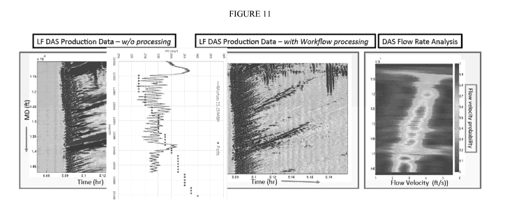
[00120] FIG. 11 displays the LF-DAS production data after the third
opening of Well 1 in
Project A, both before and after application of the Workflow. After the signal-
to-noise ratio is
increased and the noise is removed, the temperature slug is clearly
distinguishable. Thus, the
workflow improves the acquired data and allows for important information to be
distinguished
from the interferences.
[00121] The information provided by the LF-DAS signals can be utilized in
modeling
stimulations for like reservoirs or for optimizing the current stimulation
plan. For instance, the
proppant concentration can be increased at a quicker rate to open new
fractures sooner in the
fracturing process or the injection of fluids can be extended to grow new
fractures. Although
hydraulic fracturing is quite successful, even incremental improvements in
technology can mean
the difference between cost effective production and reserves that are
uneconomical to produce.
Thus, it is imperative that the noise signal and other interferences are
removed from the LF-DAS
signal using the described workflow.
[00122] Finally, there are limitations to using the DAS measurements. The
flow rate can
only be measured during the transient period because DAS measures the
temperature change, not
the absolute temperature. After flowing the well for a period of time, the
borehole temperature
reaches equilibrium so the DAS response will vanish. Also, in order to measure
velocity precisely,
we need a certain distance, which limits the spatial resolution. However, the
improvement in
signal-to-noise ratio makes up for these limitations.
[00123] The following references are incorporated by reference in their
entirety for all
purposes:
U.S. Ser. No. 15/453,434 filed March 8, 2017, entitled "Low Frequency
Distributed Acoustic
Sensing."
23
CA 03012872 2018-07-26
WO 2017/156339 PCT/US2017/021681
U.S. Ser. No. 15/453,730 filed March 8, 2017, entitled "Production Logs From
Distributed
Acoustic Sensors."
U.S. Ser. No. 15/453,517 filed March 8,2017, entitled "DAS for Well Ranging."
U.S. Ser. No. 15/453,044 filed March 8, 2017, filed March 8, 2017, entitled
"The DAS Perf-
Pump Work method of fluid distribution."
U.S. Ser. No. 15/453,650 filed March 8, 2017, entitled "Hydraulic fracture
monitoring by low-
frequency DAS."
U.S. Ser. No. 15/453,584 filed March 8,2017, entitled "Low-Frequency DAS SNR
Improvement."
Boone, Kevin, et al. "Monitoring Hydraulic Fracturing Operations Using Fiber-
Optic Distributed
Acoustic Sensing." Unconventional Resources Technology Conference, San
Antonio, Texas, 20-
22 July 2015. Society of Exploration Geophysicists, American Association of
Petroleum
Geologists, Society of Petroleum Engineers, 2015.
Webster, P., et al. "Micro-Seismic detection using distributed acoustic
sensing." SEG Technical
Program Expanded Abstracts 2013. Society of Exploration Geophysicists, 2013.
2459-2463.
Paleja, Rakesh, et al. "Velocity Tracking for Flow Monitoring and Production
Profiling Using
Distributed Acoustic Sensing." SPE Annual Technical Conference and Exhibition.
Society of
Petroleum Engineers, 2015.
US20140358444, "Method of Hydraulic Fracture Identification Using Temperature"
24