Note: Descriptions are shown in the official language in which they were submitted.
CA 03012987 2018-07-27
WO 2017/160278
PCT/US2016/022432
DUAL BORE CO-MINGLER WITH MULTIPLE POSITION INNER SLEEVE
TECHNICAL FIELD
[0001] The present disclosure generally relates to oilfield equipment and, in
particular, to
downhole tools, systems and techniques for drilling, completing and servicing
multilateral
wells. More particularly still, the present disclosure relates to systems and
methods for
selective fluid communication between a primary wellbore and secondary
wellbore extending
from the primary wellbore.
BACKGROUND
[0002] Multilateral wells typically have one or more secondary wellbores,
often referred to
as branch or lateral wellbores, extending from a primary wellbore, often
referred to as a main
or parent wellbore. The intersection between a primary wellbore and a
secondary wellbore is
often referred to as a wellbore junction. Completion equipment positioned at a
wellbore
junction for controlling fluid communication between the secondary wellbore,
the
downstream portion of the primary wellbore and the upstream portion of the
primary
wellbore may also be referred to as a junction. Such fluid communication may
involve flow
from the well, such as in the case of the production of hydrocarbons from the
various
wellbores, or may involve flow into the well, such as reservoir stimulation or
fracturing
during well intervention operations.
[0003] Various completion technologies for wellbore junctions provide for
fluid
communication between a primary and a secondary wellbore, but do not readily
permit the
flow (either into or out of) each of the wellbores to be varied or combined.
Other completion
technologies for wellbore junctions provide for varying the rate of fluid flow
into or out of a
wellbore, but do not permit fluid flow between the wellbores. In certain
instances, the entire
completion string must be retrieved from the well to establish fluid
communication with a
secondary wellbore, or with the primary wellbore below the junction.
BRIEF DESCRIPTION OF THE DRAWINGS
[0004] Various embodiments of the present disclosure will be understood more
fully from
the detailed description given below and from the accompanying drawings of
various
embodiments of the disclosure. In the drawings, like reference numbers may
indicate
1
CA 03012987 2018-07-27
WO 2017/160278
PCT/US2016/022432
identical or functionally similar elements. Embodiments are described in
detail hereinafter
with reference to the accompanying figures, in which:
[0005] Figure 1 is an elevation view in partial cross section of a land-based
multilateral
well system with a flow control system;
[0006] Figure 2 is an elevation view in partial cross section of a marine-
based multilateral
well system with a flow control system;
[0007] Figure 3 is an exploded view in partial cross section of an embodiment
of a flow
control system suitable for use in the flow control systems of Figures 1 and
2;
[0008] Figure 4 is a side view in partial cross section of a flow control sub
of the flow
control system shown in Figure 3;
[0009] Figure 5 is a close-up side view in partial cross section of a portion
of the flow
control sub shown in Figure 3;
[00010] Figure 6 is a front view in cross-section A-A of the flow control sub
shown in
Figure 5;
[00011] Figure 7-10 are side views in partial cross section of the flow
control sub of Figure
showing various paths of a guiding profile;
[00012] Figures 11-13 are side views in partial cross section of the system of
Figure 3 with
a sleeve disposed in various positions in the flow control sub; and
[00013] Figure 14 is a flowchart of a method for controlling flow with the
flow control sub
of Figure 5.
DETAILED DESCRIPTION OF THE DISCLOSURE
[00014] The disclosure may repeat reference numerals and/or letters in the
various
examples or figures. This repetition is for the purpose of simplicity and
clarity and does not
in itself dictate a relationship between the various embodiments and/or
configurations
discussed. Unless otherwise stated, spatially relative terms are intended to
encompass
different orientations of the apparatus in use or operation in addition to the
orientation
depicted in the figures.
[00015] Moreover, even though a figure may depict a horizontal wellbore or a
vertical
wellbore, unless indicated otherwise, it should be understood by those skilled
in the art that
the apparatus according to the present disclosure is equally well-suited for
use in wellbores
having other orientations including vertical wellbores, slanted wellbores,
multilateral
wellbores, or the like. Likewise, unless otherwise noted, even though a figure
may depict an
2
CA 03012987 2018-07-27
WO 2017/160278
PCT/US2016/022432
offshore operation, it should be understood by those skilled in the art that
the apparatus
according to the present disclosure is equally well-suited for use in onshore
operations and
vice-versa. Further, unless otherwise noted, even though a figure may depict a
cased hole, it
should be understood by those skilled in the art that the apparatus according
to the present
disclosure is equally well-suited for use in open hole operations.
[00016] Generally, a primary wellbore may refer to any wellbore from which
another,
intersecting wellbore has been or is to be subsequently drilled, and a
secondary wellbore may
refer to any subsequently-drilled wellbore extending from (intersecting with)
that primary
wellbore. The initial wellbore drilled from surface may be the primary
wellbore with respect
to any one or more intersecting wellbores drilled therefrom, which are the
secondary
wellbores with respect to that initial wellbore drilled from surface. Each
secondary wellbore
may then itself be the primary wellbore with respect to any further secondary
wellbore(s)
drilled therefrom.
[00017] As described further below, a multilateral well may be drilled. A flow
control
system is deployed at a junction in the wellbore where a primary wellbore and
a secondary
wellbore intersect for controlling fluid communication between the upstream
and downstream
portion of the primary wellbore and the secondary wellbore. The flow control
system may
include a flow control sub and a multiple position inner sleeve disposed
therein. The flow
control sub may have a first and second end with the first end having a single
bore and the
second end having two bores separately defined and in fluid communication with
the single
bore. Channels that have been formed along an inner surface of the flow
control sub may be
disposed opposite and in mirrored fashion from each other. The channels may
have been
formed directly in an interior surface of the flow control sub or in an
additional sub, or the
channels may have been formed in an annular sleeve that is inserted into the
flow control sub
or inserted into an additional sub. The sleeve has first and second ends with
an outer sleeve
wall extending therebetween and a first and second protrusion, which are
disposed in the
channels and may be extendable.
[00018] The channels may include multiple segments between channel endpoints;
the
protrusions are movable along the segments of the respective channels. Each
channel
endpoint may be the terminus of a segment, the intersection of two segments,
or a depression
in a segment. Endpoints may correspond to sleeve positions; for example, when
protrusions
are disposed adjacent a first endpoint in the channel, the sleeve second end
may be disposed
in one of the two bores in flow control sub second end such that sleeve is in
fluid
3
CA 03012987 2018-07-27
WO 2017/160278
PCT/US2016/022432
communication with only the selected bore. A second endpoint may correspond to
the sleeve
second end being disposed in the other of the two bores in flow control sub
second end such
that the sleeve is in fluid communication with only the selected bore.
Further, a third
endpoint may correspond to the sleeve second end being disposed in the single
bore of the
flow control sub first end thereby allowing fluids from the two bores in flow
control sub
second end to mingle in the flow control sub. One or more seals may be
disposed between
the inner surface of the flow control sub and the outer sleeve wall.
[00019] A pushing or pulling force may be applied to the sleeve form the
surface to guide
the protrusions through the segments oriented in various directions to connect
the various
endpoints, thereby maneuvering the sleeve from one position or endpoint to
another. A run-
in tool may be used to engage the sleeve and apply the pushing or pulling
force to move the
sleeve and control flow through the flow control sub. Depending on the
orientation and
geometry of the channel segments, an increased pushing or pulling force may be
needed to
effectuate a transverse motion to move the sleeve in an upward direction
whereas a decreased
force may be needed due to the effect of gravity. A deeper grooved portion of
a channel
segment may also be used to control the movement of the protrusions along the
channel
segments; in particular, at the intersection of two or more segments. When the
protrusions
reach the intersection of two or more segments, the protrusions expand or
extend into the
deeper segment portion, which prevents the extendable protrusions from
engaging an
intersecting segment.
[00020] Turning to Figures 1 and 2, shown is an elevation view in partial
cross-section of a
wellbore drilling and production system 10 utilized to produce hydrocarbons
from wellbore
12 extending through various earth strata in an oil and gas formation 14
located below the
earth's surface 16. Wellbore 12 may be a primary wellbore and may include one
or more
secondary wellbores 12a, 12b, . . . 12n, extending into the formation 14 and
disposed in any
orientation and spacing, such as the horizontal secondary wellbores 12a, 12b
illustrated.
While generally illustrated as vertical, wellbore 12, as well as any of the
other wellbores 12a,
12b, . . . 12n described, may have any orientation.
[00021] Drilling and production system 10 may include a rig or derrick 20. Rig
20 may
include a hoisting apparatus 22, a travel block 24, and a swivel 26 for
raising and lowering
casing, liner, drill pipe, work string, coiled tubing, production tubing
(including production
liner and production casing), and/or other types of pipe or tubing strings
collectively referred
to herein as tubing string 30, or other types of conveyance vehicles, such as
wireline, slickline
4
CA 03012987 2018-07-27
WO 2017/160278
PCT/US2016/022432
or cable. In Figures 1 and 2, tubing string 30 is a substantially tubular,
axially extending
work string or production casing, formed of a plurality of pipe joints coupled
together end-to-
end supporting a completion assembly as described below. Rig 20 may include a
kelly 32, a
rotary table 34, and other equipment associated with rotation and/or
translation of tubing
string 30 within a wellbore 12. For some applications, rig 18 may also include
a top drive
unit 36. Rig 20 is not limited to a particular type of system. In some
embodiments, rig 20
may be a drilling rig or a workover rig.
[00022] Rig 20 may be located proximate to a wellhead 40 as shown in Figure 1,
or spaced
apart from wellhead 40, such as in the case of an offshore arrangement as
shown in Figure 2.
One or more pressure control devices 42, such as blowout preventers (B0P5) and
other
equipment associated with drilling or producing a wellbore may also be
provided at wellhead
40 or elsewhere in the system 10.
[00023] For offshore operations, as shown in Figure 2, whether drilling or
production, rig
20 may be mounted on an oil or gas platform 44, such as the offshore platform
as illustrated,
semi-submersibles, drill ships, and the like (not shown). System 10 of Figure
2 is illustrated
as being a marine-based production system. Likewise, system 10 of Figure 1 is
illustrated as
being a land-based production system. In any event, for marine-based systems,
one or more
subsea conduits or risers 46 extend from deck 50 of platform 44 to a subsea
wellhead 40.
Tubing string 30 extends down from rig 20, through subsea conduit 46 and BOP
42 into
wellbore 12.
[00024] A working or service fluid source 52, such as a storage tank or
vessel, may supply
a working fluid 54 pumped to the upper end of tubing string 30 and flow
through tubing
string 30. Working fluid source 52 may supply any fluid utilized in wellbore
operations,
including without limitation, drilling fluid, cementious slurry, acidizing
fluid, liquid water,
steam, hydraulic fracturing fluid, propane, nitrogen, carbon dioxide or some
other type of
fluid.
[00025] Wellbore 12 may include subsurface equipment 56 disposed therein, such
as, for
example, a drill bit and bottom hole assembly (BHA), a work string with tools
carried on the
work string, a completion string and completion equipment or some other type
of wellbore
tool or equipment.
[00026] Wellbore drilling and production system 10 may generally be
characterized as
having a pipe system 58. For purposes of this disclosure, pipe system 58 may
include casing,
risers, tubing, drill strings, completion or production strings, subs, heads
or any other pipes,
CA 03012987 2018-07-27
WO 2017/160278
PCT/US2016/022432
tubes or equipment that attaches to the foregoing, such as string 30 and
conduit 46, as well as
the primary and secondary wellbores in which the pipes, casing and strings may
be deployed.
In this regard, pipe system 58 may include one or more casing strings 60 that
may be
cemented in wellbore 12, such as the surface, intermediate and production
casings 60 shown
in Figure 1. An annulus 62 is formed between the walls of sets of adjacent
tubular
components, such as concentric casing strings 60 or the exterior of tubing
string 30 and the
inside wall of wellbore 12 or casing string 60, as the case may be.
[00027] As shown in Figures 1 and 2, subsurface equipment 56 is illustrated as
completion
equipment and tubing string 30 in fluid communication with the completion
equipment 56 is
illustrated as production tubing 30. Completion equipment 56 is disposed in a
substantially
horizontal portion of wellbore 12 includes a lower completion assembly 82
having various
tools such as an orientation and alignment subassembly 84, a packer 86, a sand
control screen
assembly 88, a packer 90, a sand control screen assembly 92, a packer 94, a
sand control
screen assembly 96 and a packer 98.
[00028] Extending downhole from lower completion assembly 82 is one or more
communication cables 100, such as a sensor cable, electric cable or optic
cable, that passes
through packers 86, 90, and 94 and is operably associated with one or more
electrical devices
102 associated with lower completion assembly 82, such as sensors positioned
adjacent sand
control screen assemblies 88, 92, 96 or at the sand face of formation 14, or
downhole
controllers or actuators used to operate downhole tools or fluid flow control
devices. Cable
100 may operate as communication media, to transmit power, signals or data and
the like
between lower completion assembly 82 and an upper completion assembly 104.
[00029] In this regard, disposed in wellbore 12 at the lower end of tubing
string 30 is an
upper completion assembly 104 that includes various tools such as a packer
106, an
expansion joint 108, a packer 110, a fluid flow control module 112 and an
anchor assembly
114.
[00030] Extending uphole from upper completion assembly 104 are one or more
communication cables 116, such as a sensor cable, electric cable or optic
cable, which passes
through packers 106, 110 and extends to the surface 16. Cable 116 may operate
as
communication media, to transmit power, signals or data and the like between a
surface
controller (not pictured) and the upper and lower completion assemblies 104,
82,
respectively.
6
CA 03012987 2018-07-27
WO 2017/160278
PCT/US2016/022432
[00031] Fluids, cuttings and other debris returning to surface 16 from
wellbore 12 are
directed by a flow line 118 to storage tanks 52 and/or processing systems 120,
such as
shakers, centrifuges and the like.
[00032] In each of Figures 1 and 2, a flow control system 200 is shown
deployed in
wellbore 12 along casing string 30 in the vicinity of a secondary wellbore
12b. Although
primary wellbore 12 need not be cased for the purposes of the disclosure, in
some
embodiments, primary wellbore 12, as shown in the figures, may be at least
partially cased at
the junction with secondary wellbore 12b. In any event, flow control system
200 as deployed
at the junction between primary wellbore 12 and secondary wellbore 12b
provides selective
fluid communication with and between the wellbores utilizing a dual bore co-
mingler sub and
a multiple position inner sleeve as described in more detail below.
[00033] Figure 3 is an exploded perspective view in partial cross section of
flow control
system 200. The flow control system 200 includes a main body sub 210 and a
tubular sleeve
250. Features of the flow control system 200 may be discussed relative to a
central axis 201
of the main body sub 210. The main body sub 210 includes a first section
having a first end
211 axially spaced from a second section having a second end 212, and an outer
cylindrical
surface 213 and an inner cylindrical surface or wall 214 about the central
axis 201. Inner
cylindrical surface 214 comprises a single bore portion 215 that extends from
first end 211 to
a dual bore portion 217, which further extends to second end 212. Single bore
portion 215
comprises a first end 215a, a second end 215b, and an inner cylindrical
surface 215c that
extends therebetween, and dual bore portion 217 comprises a first end 217a, a
second end
217b, and a first through bore 218 adjacent a second through bore 219,
extending between
first and second ends 217a, 217b, respectively, and spaced apart from one
another. In one or
more embodiments, bores 218, 219 are parallel to central axis 201 and may be
formed in an
otherwise solid tubular section. Single bore first end 215a is coincident with
main body first
end 211 and dual bore second end is coincident with main body second end 212.
In one or
more embodiments, first and second through bore 218, 219, respectively, each
have a small
diameter cylindrical surface 218a, 219a, respectively, that extends from dual
bore portion
first end 217a to an internal shoulder 218b, 219b, respectively, and an
expanded diameter
cylindrical surface 218c, 219c that extends from internal shoulder 218b, 219b
to dual bore
portion second end 217b.
[00034] Figure 4 is a cross-sectional side view of an additional sub 209
coupled to and in
communication with main body first end 211. The additional sub 209 is
cylindrical with a
7
CA 03012987 2018-07-27
WO 2017/160278
PCT/US2016/022432
central axis coincident with main body central axis 201, and comprises a first
end 209a
opposite a second end 209b and an inner cylindrical surface 209c in fluid
communication
with single bore inner cylindrical surface 215c of main body sub 210. In one
or more
embodiments, additional sub 209 is longer than main body sub 210. Thus, main
body sub
210 may have a first axial length between first and second ends 211, 212,
respectively, while
additional sub 209 has a second axial length, greater than the first axial
length, between its
first and second ends 209a, 209b, respectively. Additional sub 209 further
includes an
annular seal 207 disposed along inner cylindrical surface 209c and having an
aperture 208
proximate central axis 201. Seal 207 sealingly engages surface 209c. Seal 207
may be
comprised of any suitable seal or seals known in the art including, but not
limited to,
elastomeric elements, 0-rings and T-seals. The first end 209a of the
additional sub is further
configured to couple to additional subs (not shown) with threads or other
suitable fasteners
standard in the art. In an embodiment, main body sub 210 and additional sub
209 are
integrally formed, as shown in Figure 12. In the following description, the
main body sub
210 will be described as including additional sub 209.
[00035] Referring now to Figure 5, shown is a side view of the main body sub
210 in cross
section. The single bore inner cylindrical surface 215c further includes a
channel or groove
225 comprising two or more endpoints, such as endpoints A, B, C, connected by
path
portions or segments 224, with segments interconnected to form paths as
described below. In
one or more embodiments, channel 225 is comprised of a plurality of segments
224 that
intersect one another to form channel 225.
[00036] In this regard, an endpoint may be the terminus of a segment 224, the
intersection
of two segments, or a depression or cavity formed along a segment. As will be
appreciated in
the description of the operation below, the segments may have different
orientations, such as
a horizontal segment, a forward sloping segment or a backward sloping segment.
In addition,
various segments 224 or portions of segments may have differing channel
depths, such a first
depth that is less than a second depth. For example, the hatched portion of
channel 225
shown in Figure 5 may be formed to be deeper or have an increased depth
relative to other
segments of the channel 225. Likewise, an endpoint may have a different depth,
either
shallower or deeper, than the segment along which the endpoint is defined.
[00037] One embodiment of channel 225 with interconnected path segments 222,
223, 224
is shown in Figure 5, and a cross section of the main body sub 210 with path
segments 222,
223 is shown in Figure 6; the approximate location of the cross section shown
in Figure 6 is
8
CA 03012987 2018-07-27
WO 2017/160278
PCT/US2016/022432
represented by line A-A in Figure 5. In one or more embodiments, a first
channel 225a is
formed in cylindrical surface 215c and a second channel (not shown) is formed
in cylindrical
surface 215c. Figure 5 is shown in cross section and illustrates a section
210a of main body
sub 210, it will be appreciated that in one or more embodiments, in the
opposing section 210b
of main body sub 210 (shown in Figure 6), a second channel or groove 225b
(Figure 6)
disposed opposite from and mirroring the first channel 225a may be provided,
such that the
first and second channels 225a, 225b, respectively, are aligned with one
another. In
particular, first path segment 223a of first channel 225a is disposed opposite
from and
mirroring a first path segment 223b of second channel 225b. Second path
segments 222a,
222b, of the first and second channels 225a, 225b, respectively are similarly
disposed
opposite from and mirroring one another. In other embodiments, the path
segments 222, 223,
224 of channel 225 may be configured in different patterns. In one or more
embodiments, a
second channel 225b may be disposed opposite the first channel 225a in a
mirrored or
matching pattern. In other embodiments, channel 225 may be configured in
different
geometries that are simpler or more complex with additional path segments 222,
223, 224
formed of varying lengths and configured in different directions with various
angles of
intercept. For example, in other embodiments, there may be only two endpoints
(e.g., A and
B; A and C; or B and C) instead of three (A, B, C). In the present embodiment,
the channels
225 are formed directly in the inner cylindrical surface 215c of main body sub
210; however,
in other embodiments, channels 225 may be formed in an annular sleeve that is
then inserted
into the main body sub 210, may be formed in additional sub 209, or formed in
an annular
sleeve that in then inserted into the additional sub 209. It will be
appreciated that while
channel 225 is illustrated in proximity to second end 215b, channel 225 may be
defined
anywhere along single bore portion 215 between first end 215a and second end
215b. In this
same vein, endpoints A and B of channel 225 need not be adjacent first and
second through
bore 218, 219, respectively, but may be spaced apart therefrom.
[00038] Referring now to Figures 7-10, shown is the side view of main body sub
210 in
cross section of Figure 5 with various paths marked through channel 225. In
particular,
Figure 7 shows a path 226 from A to B; Figure 8 shows a path 227 from B to C;
Figure 9
shows a path 228 from C to A; and Figure 10 shows a path 229 from B to A.
These paths
226, 227, 228, 229 will be described in further detail below.
[00039] Referring again to Figure 3, tubular sleeve 250 comprises a central
axis 205, a first
end 251, a second end 252, a cylindrical portion 257, and a through bore 258.
In one or more
9
CA 03012987 2018-07-27
WO 2017/160278
PCT/US2016/022432
embodiments, sleeve 250 may further comprise a frustoconical portion or
scoophead 255.
Scoophead 255 includes a first end 255a coincident with sleeve first end 251,
a second end
255b, a frustoconical surface 255c extending therebetween, and a through bore
256 in fluid
communication with the cylindrical portion through bore 258. Frustoconical
surface 255c
extends from first end 255a radially inward toward central axis 205 and
axially to second end
255b. Cylindrical portion 257 has an outer cylindrical surface 257a that
extends from
frustoconical portion second end 255b to sleeve second end 252. Scoophead may
be made
from a flexible material or any other suitable material known in the art. A
protrusion 265 is
disposed along outer cylindrical surface 257a. In one or more embodiments,
sleeve 250
includes first and second protrusions 265a, 265b, respectively, disposed
radially opposite one
another on cylindrical portion 257 and spaced away from sleeve second end 252.
In one or
more embodiments, protrusions 265a, 265b extend radially outward from
cylindrical portion
257 and are configured to move radially inward and outward in response to an
external
structure. Follower or protrusion 265 may include, for example, retractable
lugs and spring
plungers. Extendable protrusion 265 is sized to engage and move within channel
225 as
described below. In the present embodiment, extendable protrusions 265a, 265b
are
retractable lugs. Retractable lugs 265a, 265b extend radially beyond outer
cylindrical surface
257c a predetermined minimum distance such that even in a fully retracted
position,
retractable lugs 265a, 265b still extend radially beyond outer cylindrical
surface 257c.
Further, disposed proximate sleeve second end 252 is a seal 270. Seal 270 may
be comprised
of any suitable seal or seals known in the art including, but not limited to,
an elastomeric
element, 0-rings and T-seals.
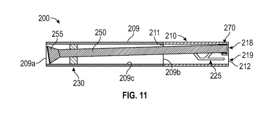
[00040] Referring now to Figures 11-13, shown are side views in partial cross
section of
the main body sub 210 and additional sub 209 of Figure 4 with sleeve 250
disposed therein in
various positions. Sleeve 250 is disposed in main body sub 210 and additional
sub 209 such
that scoophead 255 of sleeve 250 is disposed on one side of the seal 207
proximate additional
sub first end 209a and the sleeve second end 252 is disposed on the other side
of seal 207
proximate main body second end 212. In particular, seal 207 is configured to
allow
cylindrical portion 257 of sleeve 250 to pass sealingly there through while
also providing a
seal against inner cylindrical surface 209c. Further, sleeve 250 is positioned
in main body
sub 210 and sub 209 such that retractable protrusion 265 is sized to fit in
channel 225. To the
extent first and second channels 225a, 225b, respectively, are defined, then
first and second
retractable protrusions 265a, 265b, respectively, are likewise provided and
each disposed to
CA 03012987 2018-07-27
WO 2017/160278
PCT/US2016/022432
extend into a corresponding channel 225a, 225b, respectively (see Figure 6).
As the
retractable lugs 265a, 265b are urged through first and second channels 225a,
225b,
respectively, concurrently, sleeve second end 252 is guided to various
positions in single bore
portion 215 and dual bore portion 217 of main body sub 210. Thus, the first
and second
channels 225a, 225b, respectively, form a guiding profile for sleeve 250.
[00041] Referring again to Figure 5, in the present embodiment, sleeve 250 may
be
maneuvered into one of three positions: position A, position B, or position C.
Operation will
be described with two channels 225 and two retractable protrusions 265. When
sleeve 250 is
in position A, retractable lugs 265a, 265b are located adjacent endpoint A in
guiding profile
225 and sleeve second end 252 is disposed in first through bore 218 of main
body sub 210
(see Figure 11) so that sleeve 250 is in fluid communication only with first
through bore 218;
when sleeve 250 is in position B, retractable lugs 265a, 265b are located
adjacent endpoint B
and sleeve second end 252 is disposed in second through bore 219 of main body
sub 210
(Figure 12) so that sleeve 250 is in fluid communication only with second
through bore 219;
and when sleeve 250 is in position C, retractable lugs 265a, 265b are located
adjacent
endpoint C and sleeve second end 252 is disposed in single bore portion 215
(Figure 13)
spaced apart from bores 218, 219 so that sleeve 250 is in fluid communication
with both first
and second through bores 218, 219. It will be appreciated that in position C,
flow from bores
218, 219 can comingle, while in positions A and B, flow into and out of
through bores 218,
219, respectively, is isolated. Sleeve 250 may be preinstalled in main body
sub 210 before
system 200 is run-in and positioned in a wellbore 12. In this regard, sleeve
250 may be in
one of two positions¨position A or position B¨before system 200 is installed
downhole;
the preinstalled position is determined based on which wellbore will be
subject to downhole
operations first (i.e., the wellbore in fluid communication with first through
bore 218 or the
wellbore in fluid communication with second through bore 219. By having the
sleeve 250
preinstalled in one of the first and second through bores 218, 219,
respectively, in dual bore
portion 217, work can be performed and the sleeve 250 can then be shifted to
the other bore
without having to trip system 200 out of wellbore 12. In the present
embodiment, sleeve 250
is preinstalled in position A (Figure 11); however, in other embodiments,
sleeve 250 may be
preinstalled in position B (Figure 12). In yet further embodiments, it may be
desired to allow
mingling of fluid from the first and second through bore 218, 219,
respectively, before any
work is performed in either through bore 218, 219, in which case, the sleeve
250 will be
preinstalled in position C (Figure 13).
CA 03012987 2018-07-27
WO 2017/160278
PCT/US2016/022432
[00042] While the flow control system 200 described herein is not limited to
use in a
wellbore of a particular orientation, in one or more embodiments, flow control
system 200
may be deployed in a substantially horizontal primary wellbore that has one or
more
secondary wellbores intersecting therewith. The following descriptions of
operation are but
one embodiment of the operation of flow control system 200. In the following
operational
embodiments, flow control system 200 is deployed in a substantially horizontal
wellbore such
that the horizontal portion of the wellbore has one side "above" the other
side for purposes of
orientation. Referring now to Figures 7-10, sleeve 250 may be maneuvered
reciprocatingly
via retractable lugs 265 through the various paths 226, 227, 228, 229 between
endpoints A, B,
C in main body sub 210. In one or more embodiments, a run-in tool (not shown)
that engages
sleeve 250 may be used to apply the pushing (down wellbore) or pulling (up
wellbore) force
necessary to guide sleeve 250 along a segment of channel 225. The run-in tool
may be any
tool known in the art and may be carried on any type of deployment vehicle,
including but
not limited to, drill pipe, production tubing, coiled tubing, slick line, and
wireline.
[00043] In any event, when the sleeve 250 is installed in main body sub 210 in
position A
(see Figures 5 and 11), second through bore 219 is isolated from upstream
fluid
communication while allowing upstream fluid communication with first through
bore 218.
When the desired operation requiring selective fluid communication with first
through bore
218 (and any secondary or lateral wellbore in communication therewith) is
completed, sleeve
250 can be adjusted to a different position, i.e., position B or C for
additional operations. In
other words, the sleeve 250 is moved from position A (Figure 11) to position B
(Figure 12)
by manipulating sleeve 250 so that retractable lugs 265a, 265b of sleeve 250
are guided along
path 226 shown in Figure 7. In particular, a force is applied to pull sleeve
250 along path 226
such that retractable lugs travel axially along segment 230 of path 226 until
lugs 265 reach
segment 231, where gravity or a continued pulling force causes lugs 265to then
travel along
segment 231. Lugs 265 will then reach segment 232 and continue to be pulled
until the lugs
265 reach segment 234. At this point, to move lugs 265 along segment 234 in an
upward
direction, a significant increase in the pulling force would be needed. Thus,
operators at the
surface would understand that lugs 265 were positioned at the junction of
segment 234 and
segment 232. In other words, under an upward pulling force sleeve 250 will be
unable to be
pulled any further without a transverse motion to lift the sleeve 250 up, such
motion
occurring only under a significantly increased pulling force. Rather, sleeve
250 may be
pushed further downhole, moving lugs 265 axially along segment 232 until the
lugs 265
12
CA 03012987 2018-07-27
WO 2017/160278
PCT/US2016/022432
reach endpoint B and sleeve 250 seats in bore 219. In such case, seal 270
engages expanded
diameter cylindrical surface 219c of second through bore 219 as shown in
Figure 12.
[00044] To the extent it is desired to establish fluid communication with both
through
bores 218, 219, the sleeve 250 may be moved to position C (see Figure 13).
With respect to
fluid flow from the well 12, this position C allows flow from both the first
and second
through bores 218, 219, respectively, to co-mingle and enter single bore
portion 215 of main
body sub 210. As an example, to move sleeve 250 from position B (Figure 12) to
position C
(Figure 13), retractable lugs 265 of sleeve 250 are guided along path 227
shown in Figure 8
by pulling sleeve 250 along path 227 such that retractable lugs 265 travel
axially along
segments 232 and 233 of path 227 until lugs 265 reach the intersection 233a of
segments 233
and 234. As previously discussed, an appreciable increase in the upstream
pulling force
applied to sleeve 250 is necessary to effectuate a transverse motion to move
the sleeve 250 in
an upward direction along segment 234. At the point where lugs 265 reach the
intersection of
segments 234 and 235, the pulling force necessary to continue to move sleeve
250 along
channel 227, and in particular, segment 235, will decrease. Likewise, because
of the effect of
gravity as the lugs 265 are guided along segment 236, the pulling force will
decrease even
more as sleeve 250 is moved along path 227 toward endpoint C as shown in
Figure 13.
[00045] Referring now to Figure 9, shown is main body sub 210 with arrows
indicating a
path 228 from endpoint C to endpoint A along channel 225. When it is desired
to move the
sleeve 250 into position A from endpoint C, the downward (or pushing) applied
force must be
increased to urge sleeve 250 in an upward direction along segment 236 until
lugs 265 reach
segment 237, at which point, resistance will decrease (and hence the force
necessary to urge
sleeve 250 along segment 237). Continued application of downward force (or
pushing force)
will urge sleeve 250 along segment 237 until the intersection with segment 238
is reached, at
which point, resistance to the downward force will again decrease as sleeve
250 moves along
segment 238. Finally, continued application of a downward force with urge
sleeve 250 along
segment 239 until endpoint A is reached.
[00046] In one or more embodiments, it will be appreciated that when lugs 265
of sleeve
250 reach the intersection 237a of segments 234 and 237, gravity would
normally cause the
lugs 265 to engage segment 234 as opposed to continuing along segment 237. To
prevent
this downward movement, a portion of guiding profile 225 is configured to have
a deeper
groove 240 (hatched portion in segment 237) than the remaining guiding profile
225 such that
when lugs 265 reach the intersection 237a, the retractable lugs 265 will
expand into the
13
CA 03012987 2018-07-27
WO 2017/160278
PCT/US2016/022432
deeper groove 240 in segment 237 and prevent the sleeve 250 from engaging
segment 234.
In one or more embodiments, the deeper groove 240 begins before intersection
237a and
extends along segment 237 to a point past intersection 237a such that a
shoulder formed at
the intersection of the two segments 237, 234 prevents lugs 265 from engaging
segment 234.
In other embodiments, and depending on the desired preinstalled position of
sleeve 250 and
geometry of the guiding profile 225, the deeper groove portion 240 may be
located in another
segment. In this regard, deeper groove portion 240 is generally positioned
anywhere along
channel 225 to prevent the retractable lugs 265 from engaging an intersecting
segment. This
is particularly desirable where gravity may otherwise urge lugs 265 to engage
the intersecting
segment.
[00047] Referring now to Figure 10, shown is main body sub 210 with arrows
indicating a
path 229 from endpoint B to endpoint A along channel 225. It may be desired to
move sleeve
250 from position B to position A. In particular, to move the sleeve 250 from
position B
(Figure 12) to position A (Figure 11) the retractable lugs 265 of sleeve 250
are guided along
path 229 shown in Figure 10 by pulling sleeve 250 along path 229 such that
retractable lugs
travel axially along segments 232 and 233 of path 229 until lugs 265 reach the
intersection
233a of segments 233 and 234. As previously discussed, an appreciable increase
in upstream
pulling force applied to sleeve 250 is necessary to effectuate a transverse
motion to move the
sleeve 250 in an upward direction along segment 234. When lugs 265 reach the
intersection
237a of segments 234 and 237, the retractable lugs 265 will expand into the
deeper groove
240 in segment 237 and prevent the sleeve 250 from reengaging segment 234. The
pushing
force will decrease because of the effect of gravity as the lugs 265 are
guided along segment
238. Once lugs 265 reach endpoint A, seal 270 engages expanded diameter
cylindrical
surface 218c of first through bore 218 as shown in Figure 11.
[00048] Guiding profile 225 with retractable lugs 265 on sleeve 250 allow the
sleeve 250
to maneuver between positions A, B, and C as many times as needed or desired
without
having to trip system 200 out of wellbore 12. Combinations of the previously
described paths
226, 227, 228, 229 may also be used to maneuver the sleeve 250 from position A
to position
C or from position C to position B. For example, segments 230, 231 of path 226
(Figure 7)
may be combined with segments 233, 234, 235, 236 of path 227 (Figure 8) to
move sleeve
250 from position A to position C. Similarly, segments 236, 235, 237, 238 of
path 228
(Figure 9) may be combined with segments 230, 231, 232 of path 226 (Figure 7)
to move
sleeve 250 from position C to position B.
14
CA 03012987 2018-07-27
WO 2017/160278
PCT/US2016/022432
[00049] As previously discussed, in other embodiments, channel 225 may be
configured in
different geometries that are simpler or more complex. For example, if only
one movement
is needed, such as from position A to position B and no other movement
thereafter is needed,
guiding profile 225 need only comprise segments 230, 231, 232 that make up
path 226.
Guiding profile 225 may further be configured to provide one path and allow
only one cycle
or movement of the sleeve 250. Additionally, where guiding profile 225
comprises one path,
protrusions 265 disposed in guiding profile 225 may, but need not, be
extendable.
[00050] In the present embodiment, system 200 is installed in a horizontal
well; however,
in other embodiments, system 200 may be installed in a well with an
inclination where the
guiding profile 225 will be relied on solely for maneuvering sleeve 250
between positions A,
B, C without gravity affecting the lugs 265 as they move through guiding
profile 225.
[00051] Referring now to Figure 14 and with reference to Figures 1 through 13,
exemplary
embodiments of an operational procedure 300 for controlling flow in a wellbore
12 are
described that employ the flow control system 200 described above. Initially,
at step 304, the
flow control sub 210 is positioned in a well 12 such that first through bore
218 of the flow
control sub 210 is in fluid communication with a primary wellbore 12 and
second through
bore 219 is in fluid communication with a secondary wellbore 12n. At step 308,
a force is
applied to sleeve 250, which is disposed in the flow control sub 210 in a
first position. The
applied force may be in the form of pushing (down wellbore) or pulling (up
wellbore) the
sleeve, and may also include the effects of gravity. Further, when in the
first position, the
sleeve 250 may be disposed in flow control sub 210 such that sleeve 250 is
placed in fluid
communication with only the primary wellbore via first through bore 218, only
the secondary
wellbore via second through bore 219, or both the primary and secondary
wellbores. Further
still, one or more seals 230, 270 may be disposed between the sleeve 250 and
the flow control
sub 210.
[00052] At step 312, extendable protrusions 265 disposed proximate one end 252
of the
sleeve 250 on outer surface 257a are moved along channels 225 in inner surface
215c of the
flow control sub 210. Channels 225 comprise a first and second channel 225a,
225b disposed
opposite from and mirroring each other; each channel 225a, 225b further
comprises a
plurality of interconnected segments 224 that may have different orientations
and depths and
may intersect one another. Extendable protrusions 265a, 265b extend into and
move along
channels 225a, 225b, respectively, as the sleeve 250 undergoes any pushing,
pulling, or
transverse motions, any of which may also be impacted by gravity, or any
combination
CA 03012987 2018-07-27
WO 2017/160278
PCT/US2016/022432
thereof (step 308). Moreover, the movement of the extendable protrusions 265
through the
channels 225 can be controlled by deepening a portion of channel 225. When the
extendable
protrusions 265 reach a deeper channel 225 portion, the extendable protrusions
265 expand
into the deeper groove 237, which allows the extendable protrusions 265 to
resist gravity and
prevent protrusions 265 from entering any intersecting channel segments.
[00053] At step 316, the sleeve 250 is moved from the first position to a
second position in
the flow control sub 210; and at step 320, the sleeve 250 is placed in fluid
communication
with at least one of the first and second bores 218, 219, respectively, of the
fluid control sub
210. In particular, when in the second position, the sleeve 250 may be
disposed in flow
control sub 210 such that sleeve 250 is placed in fluid communication with
only the primary
wellbore via first through bore 218, only the secondary wellbore via second
through bore
219, or both the primary and secondary wellbores. Further, when sleeve 250 is
placed in
fluid communication with one of the first and second bores 218, 219,
respectively, flow
through one of the first and second bores 218, 219, respectively, of the flow
control sub 210
is in upstream fluid communication, while flow through the other of the first
and second
bores 218, 219, respectively, of the flow control sub 210 is isolated from
upstream fluid
communication. The sleeve 250 may be further moved to a third position in the
flow control
sub 210, in which flow through the first and second bores 218, 219 of the flow
control sub
210 is allowed to mingle in the flow control sub 210 and is in upstream fluid
communication.
[00054] Thus, a flow control system has been described. Embodiments of the
flow control
system for oil and gas wells may generally include a main body sub, having a
first section
with a single bore, and a second section with two adjacent through bores in
fluid
communication with the single bore of the first section, a guide channel along
an inner wall
of the single bore, and a sleeve having a through bore is movably positionable
in the main
body with a protrusion on the sleeve riding in the guide channel to guide
reciprocating
movement of the sleeve within the main body. Other embodiments of a flow
control system
for oil and gas wells may generally include a main body sub having first and
second ends, the
main body first end having a single bore formed therein, the single bore
defined by a wall
having an inner surface, the single bore in fluid communication with two
through bores
separately defined in the main body second end; a channel formed along the
inner surface;
and a sleeve disposed in the main body, the sleeve having a first end and a
second end with
an outer sleeve wall extending therebetween, the sleeve further including a
protrusion, which
may be extendable, disposed along the outer sleeve surface and seated in the
channel.
16
CA 03012987 2018-07-27
WO 2017/160278
PCT/US2016/022432
Likewise, a system for controlling fluid flow in multilateral wellbore
completions may
generally include a flow control sub having a first bore in a first section in
fluid
communication with a second and third bore in a second section, a primary
wellbore tubular
in fluid communication with one of the second and third bores, a secondary
wellbore tubular
in fluid communication with the other of the second and third bores, a sleeve
having a
through bore disposed in the flow control sub with a first and second
retractable lug, and a
guiding channel having at least three interconnected endpoints, the channel
disposed in an
inner wall of the flow control sub, wherein the first and second retractable
lugs are disposed
in the guiding channel. Other embodiments of a system for controlling fluid
flow in
multilateral wellbore completions may generally include a primary wellbore
tubular; a
secondary wellbore tubular; a flow control sub having a first bore at a first
end and a second
and third bore at a second end, the first bore being in fluid communication
with the second
and third bores, one of the second or third bores being in fluid communication
with the
primary wellbore tubular and the other of the second or third bores being in
fluid
communication with the secondary wellbore tubular; a sleeve disposed in the
flow control
sub, the sleeve having a first end, a second end, and a first and second
retractable lug
disposed proximate the sleeve second end; and a guiding channel having at
least three
interconnected endpoints, the channel disposed in an inner cylindrical surface
of the flow
control sub, wherein one of the endpoints is uniquely associated with the
second bore of the
flow control sub and one of the endpoints is uniquely associated with the
third bore; wherein
the first and second retractable lugs are disposed in the guiding channel.
Other embodiments
of a system for controlling fluid flow in multilateral wellbore completions
may generally
include a primary wellbore tubular; a secondary wellbore tubular; a flow
control sub having a
first bore at a first end and a second and third bore at a second end, the
first bore being in
fluid communication with the second and third bores, one of the second or
third bores being
in fluid communication with the primary wellbore tubular and the other of the
second or third
bores being in fluid communication with the secondary wellbore tubular; a
sleeve disposed in
the flow control sub, the sleeve having a first end, a second end, and a first
and second
retractable lug disposed proximate the sleeve second end; and a guiding
channel having at
least two interconnected endpoints, the channel disposed in an inner
cylindrical surface of the
flow control sub, wherein one of the endpoints is uniquely associated with one
of the second
and third bores of the flow control sub; wherein the first and second
retractable lugs are
disposed in the guiding channel.
17
CA 03012987 2018-07-27
WO 2017/160278
PCT/US2016/022432
[00055] For any of the foregoing embodiments, the flow control system may
include any
one of the following elements, alone or in combination with each other:
[00056] A first and second channel in the inner wall of the single bore, and a
first
protrusion is disposed in the first channel and a second protrusion is
disposed in the second
channel.
[00057] A first portion of the sleeve is disposed in an additional sub coupled
to and in fluid
communication with the main body.
[00058] A second portion of the sleeve is sealingly disposed in one of the two
adjacent
through bores of the main body second section.
[00059] The guide channel has two different, spaced apart endpoints, where the
first
endpoint is associated with one of the two adjacent through bores of the main
body second
section and the second endpoint is associated with the other of the two
adjacent through bores
of the main body second section.
[00060] The guide channel has a third endpoint and the first, second and third
endpoints
are joined together by a plurality of segments forming the guide channel.
[00061] A portion of the guide channel has a depth that is different than
another portion of
the guide channel, and the protrusion on the sleeve are extendable.
[00062] The two adjacent through bores are parallel to each other.
[00063] An additional sub having a bore, coupled to the main body, and in
fluid
communication with the main body single bore, wherein the main body is
characterized by a
first axial length and the additional sub is characterized by a second axial
length, wherein the
second axial length of the additional sub is greater than the first axial
length of the main body
and a seal engages the inner cylindrical surface of the additional sub.
[00064] The guiding channel has a first depth and a portion of the guiding
channel has a
second depth deeper than the first depth, the deeper second portion positioned
at an
intersection of two guiding channel segments.
[00065] The sleeve further comprises a first seal sealingly engaging a
cylindrical surface
of one of the second and third bores of the flow control sub second end when
the first and
second retractable lugs are adjacent an endpoint, wherein the flow control sub
further
comprises a second seal sealingly engaging the cylindrical surface of the flow
control sub
first bore and sealingly engaging the sleeve, the sleeve extending through an
aperture formed
in the seal.
18
CA 03012987 2018-07-27
WO 2017/160278
PCT/US2016/022432
[00066] The main body comprises a first and second channel in the inner
surface of the
single bore, and a first protrusion is disposed in the first channel and a
second protrusion is
disposed in the second channel.
[00067] The protrusions are extendable.
[00068] The sleeve first end is disposed in an additional sub coupled to and
in fluid
communication with main body.
[00069] The sleeve second end is sealingly disposed in one of the two through
bores of the
main body second end.
[00070] The channel has two different, spaced apart endpoints, where the first
endpoint is
associated with the first bore of the main body dual bore and the second
endpoint is
associated with the second bore of the main body dual bore.
[00071] The channel has a third endpoint and the first, second and third
endpoints are
joined together by a plurality of segments forming the channel.
[00072] A portion of the channel has a depth that is different than another
portion of the
channel.
[00073] A seal disposed along the outer sleeve wall between the protrusion and
the first
end.
[00074] A seal disposed along the inner main body surface, the seal having an
aperture.
[00075] A seal disposed along the outer sleeve wall between the protrusion and
the second
end.
[00076] An additional sub coupled to and in fluid communication with the main
body first
end, the additional sub having an inner cylindrical surface; wherein the main
body is
characterized by a first length between its two ends and the additional sub is
characterized by
a second length between its two ends, wherein the second length of the
additional sub is
greater than the first length of the main body; wherein the seal engages the
inner cylindrical
surface of the additional sub.
[00077] An additional sub coupled to and in fluid communication with the main
body first
end, the additional sub having an inner cylindrical surface; wherein the main
body is
characterized by a first length between its two ends and the additional sub is
characterized by
a second length between its two ends, wherein the second length of the
additional sub is less
than the first length of the main body; wherein the seal engages the inner
cylindrical surface
of the additional sub.
19
CA 03012987 2018-07-27
WO 2017/160278
PCT/US2016/022432
[00078] The channel is formed in an annular sleeve, and the annular sleeve is
disposed in
the main body sub.
[00079] The channel is formed in an annular sleeve, and the annular sleeve is
disposed in
the additional sub.
[00080] The channel is formed in an annular sleeve, a portion of the annular
sleeve is
disposed in the additional sub and a portion of the annular sleeve is disposed
in the main
body sub.
[00081] The channel comprises a plurality of segments having varying lengths,
angles of
intercept, and depths.
[00082] The channel has a first depth and a portion of the channel has a
second depth
deeper than the first depth, the deeper second portion positioned at an
intersection of two
channel segments.
[00083] An additional sub coupled to and in fluid communication with the main
body first
end, the additional sub having an inner cylindrical surface; wherein the main
body is
characterized by a first length between its two ends and the additional sub is
characterized by
a second length between its two ends, wherein the second length of the
additional sub is
greater than the first length of the main body; wherein an additional seal
engages the inner
cylindrical surface of the additional sub and the outer sleeve wall of the
sleeve.
[00084] The channel comprises one segment between the first and second
endpoints.
[00085] The guiding channel has a first depth and a portion of the guiding
channel has a
second depth deeper than the first depth, the deeper second portion positioned
at an
intersection of two channel segments.
[00086] The sleeve further comprises a first seal disposed at the sleeve
second end
sealingly engaging a cylindrical surface of one of the second and third bores
of the flow
control sub second end when the first and second retractable lugs are adjacent
an endpoint,
wherein the flow control sub further comprises a second seal disposed
proximate flow control
sub first end and sealingly engaging the cylindrical surface of the flow
control sub first bore
and sealingly engaging the sleeve, the sleeve extending through an aperture
formed in the
seal.
[00087] The sleeve first end is disposed in an additional sub coupled to and
in fluid
communication with the flow control sub.
[00088] The guiding channel has a third endpoint and the first, second and
third endpoints
are joined together by a plurality of segments forming the guiding channel.
CA 03012987 2018-07-27
WO 2017/160278
PCT/US2016/022432
[00089] An additional sub coupled to and in fluid communication with the flow
control
sub first end, the additional sub having an inner cylindrical surface; wherein
the flow control
sub is characterized by a first length between its two ends and the additional
sub is
characterized by a second length between its two ends, wherein the second
length of the
additional sub is greater than the first length of the flow control sub;
wherein the seal engages
the inner cylindrical surface of the additional sub.
[00090] An additional sub coupled to and in fluid communication with the flow
control
sub first end, the additional sub having an inner cylindrical surface; wherein
the flow control
sub is characterized by a first length between its two ends and the additional
sub is
characterized by a second length between its two ends, wherein the second
length of the
additional sub is less than the first length of the flow control sub; wherein
a seal engages the
inner cylindrical surface of the additional sub.
[00091] The guiding channel is formed in an annular sleeve, and the annular
sleeve is
disposed in the flow control sub.
[00092] The guiding channel is formed in an annular sleeve, and the annular
sleeve is
disposed in the additional sub.
[00093] The guiding channel is formed in an annular sleeve, a portion of the
annular
sleeve is disposed in the additional sub and a portion of the annular sleeve
is disposed in the
flow control sub.
[00094] The guiding channel comprises a plurality of segments having varying
lengths,
angles of intercept, and depths.
[00095] An additional sub coupled to and in fluid communication with the flow
control
sub first end, the additional sub having an inner cylindrical surface; wherein
the flow control
sub is characterized by a first length between its two ends and the additional
sub is
characterized by a second length between its two ends, wherein the second
length of the
additional sub is greater than the first length of the flow control sub;
wherein a seal engages
the inner cylindrical surface of the additional sub and the outer sleeve wall
of the sleeve.
[00096] The guiding channel comprises one segment between the first and second
endpoints.
[00097] A method for controlling flow in multilateral well completions has
been
described. The method may generally include positioning a flow control sub in
a multilateral
well where a first bore of the flow control sub is in fluid communication with
a primary
wellbore and second bore is in fluid communication with a secondary wellbore,
applying a
21
CA 03012987 2018-07-27
WO 2017/160278
PCT/US2016/022432
force to a sleeve having a through bore and disposed in the flow control sub
in a first
position, moving protrusions disposed on the sleeve along channels disposed in
an inner wall
of the flow control sub, moving the sleeve from the first position to a second
position in the
flow control sub, and placing the sleeve in fluid communication with at least
one of the first
and second bores of the flow control sub. Other embodiments of a method for
controlling
flow in multilateral well completions may generally include positioning a flow
control sub in
a multilateral well where a first bore of the flow control sub is in fluid
communication with a
primary wellbore and second bore is in fluid communication with a secondary
wellbore,
applying a force to a sleeve disposed in the flow control sub in a first
position, moving
protrusions disposed on an outer surface of the sleeve along channels disposed
in an inner
surface of the flow control sub, moving the sleeve from the first position to
a second position
in the flow control sub, and placing the sleeve in fluid communication with at
least one of the
first and second bores of the flow control sub. Other embodiments of a method
for
controlling flow in multilateral well completions may generally include a
method for
controlling flow in multilateral well completions may generally include moving
protrusions
disposed on an outer surface of a sleeve along channels disposed in an inner
surface of a flow
control sub, the sleeve being disposed in the flow control sub in a first
position, moving the
sleeve from the first position to a second position in the flow control sub,
and placing the
sleeve in fluid communication with at least one of a first bore of the flow
control sub in fluid
communication with a primary wellbore and second bore in fluid communication
with a
secondary wellbore.
[00098] For the foregoing embodiments, the method may include any one of the
following
steps, alone or in combination with each other:
[00099] The applying a force step comprises at least one of: pulling the
sleeve, pushing
the sleeve, and allowing gravity to impact the sleeve.
[000100] Providing at least one seal between the sleeve and the flow control
sub.
[000101] Controlling movement of the protrusions within the channels by
deepening a
portion of the channels at an intersection of channel segments, extending the
protrusions
radially outward into the deeper portion of the channels, and moving the
protrusions along
the deeper channel portion and passing intersecting channel segments.
[000102] Positioning a flow control sub in a multilateral well comprises
placing the sleeve
in fluid communication with one of the first and second bores of the fluid
control sub.
22
CA 03012987 2018-07-27
WO 2017/160278
PCT/US2016/022432
[000103] The sleeve is in the first or second position, flow through one of
the first and
second bores of the flow control sub is in upstream fluid communication, while
flow through
the other of the first and second bores of the flow control sub is isolated
from upstream fluid
communication.
[000104] Moving the sleeve to a third position in the flow control sub, and
allowing flow
through the first and second bore of the flow control sub to mingle in the
flow control sub.
[000105] The positioning a flow control sub in a multilateral well comprises
placing the
sleeve in fluid communication with both the first and second bores of the
fluid control sub.
[000106] The applying a force step comprises at least one of: pulling the
sleeve, pushing
the sleeve, and allowing gravity to impact the sleeve.
[000107] Providing at least one seal between the sleeve and the flow control
sub.
[000108] Controlling movement of the extendable protrusions within the
channels by
deepening a portion of the channels at an intersection of channel segments;
extending the
extendable protrusions radially outward into the deeper portion of the
channels; and moving
the extendable protrusions along the deeper channel portion and passing
intersecting channel
segments.
[000109] The positioning a flow control sub in a multilateral well step
comprises placing
the sleeve is in fluid communication with one of the first and second bores of
the fluid control
sub.
[000110] The sleeve, when in the first or second position, places flow through
one of the
first and second bores of the flow control sub in upstream fluid
communication, while
isolating flow through the other of the first and second bores of the flow
control sub from
upstream fluid communication.
[000111] When the sleeve is in the first or second position, flow through one
of the first and
second bores of the flow control sub is in upstream fluid communication, while
flow through
the other of the first and second bores of the flow control sub is isolated
from upstream fluid
communication
[000112] Moving the sleeve to a third position in the flow control sub; and
allowing flow
through the first and second bore of the flow control sub to mingle in the
flow control sub.
[000113] Moving the sleeve to a third position in the flow control sub; and
placing the
sleeve in fluid communication with flow both the first and second bores of the
flow control
sub.
23
CA 03012987 2018-07-27
WO 2017/160278
PCT/US2016/022432
[000114] Placing flow through the first and second bores of the flow control
sub in
upstream fluid communication.
[000115] The positioning of a flow control sub in a multilateral well step
comprises placing
the sleeve in fluid communication with both the first and second bores of the
fluid control
sub.
[000116] Moving the sleeve in a transverse motion.
[000117] Moving the sleeve in an upward motion.
[000118] Increasing the force to move protrusions along an inclined portion of
the channels.
[000119] Increasing the force to move protrusions in a transverse motion along
the
channels.
[000120] Moving the protrusions axially along a segment of the channels.
[000121] Decreasing the force to move protrusions along an inclined portion of
the
channels.
[000122] Isolating flow through one of the first and second bores of the flow
control sub
from upstream fluid communication.
[000123] Placing an additional sub in fluid communication with the flow
control sub, and
moving the protrusions along channels disposed in an inner surface of the
additional sub.
[000124] Sealingly disposing a sleeve end in one of the first and second bores
of the flow
control sub.
[000125] Sealingly disposing the sleeve in the flow control sub.
[000126] Deepening a portion of the channels at an intersection of channels;
extending the
protrusions radially outward into the deeper portion of the channels; and
moving the
protrusions along the deeper channel portion and passing intersecting channel
segments.
[000127] Moving the extendable protrusions along a deeper portion of the
channels past an
intersection of channel segments.
[000128] The moving protrusions step comprises applying a force of at least
one of: pulling
the sleeve, pushing the sleeve, and allowing gravity to impact the sleeve.
[000129] Providing at least one seal between the sleeve and the flow control
sub.
[000130] Controlling movement of the protrusions within the channels by
deepening a
portion of the channels at an intersection of channel segments; extending the
protrusions
radially outward into the deeper portion of the channels; and moving the
protrusions along
the deeper channel portion and passing intersecting channel segments.
24
CA 03012987 2018-07-27
WO 2017/160278
PCT/US2016/022432
[000131] Placing the sleeve in fluid communication with one of the first and
second bores
of the fluid control sub.
[000132] When the sleeve is in the first or second position, flow through one
of the first and
second bores of the flow control sub is in upstream fluid communication, while
flow through
the other of the first and second bores of the flow control sub is isolated
from upstream fluid
communication.
[000133] Moving the sleeve to a third position in the flow control sub; and
allowing flow
through the first and second bore of the flow control sub to mingle in the
flow control sub.
[000134] Placing the sleeve in fluid communication with both the first and
second bores of
the fluid control sub.
[000135] Although various embodiments and methods have been shown and
described, the
disclosure is not limited to such embodiments and methods and will be
understood to include
all modifications and variations as would be apparent to one skilled in the
art. Therefore, it
should be understood that the disclosure is not intended to be limited to the
particular forms
disclosed. Rather, the intention is to cover all modifications, equivalents,
and alternatives
falling within the spirit and scope of the disclosure as defined by the
appended claims.