Note: Descriptions are shown in the official language in which they were submitted.
1
PACKAGES FOR THE TRANSPORT OF TUBES
FIELD OF THE INVENTION
The present invention relates to improvements in or relating to packaging and
particularly
relates to a package of tubes and a tray or cover therefor.
BACKGROUND OF THE INVENTION
Collapsible tubes, such as those used for products like toothpaste are
normally made of
aluminum or of other soft metal or plastic, and consist of a thin body which
can be deformed to
express the contents of the tube, the body having at one end a shoulder of
rather heavier metal
which terminates in a central neck to which a cap may be removably secured.
Such collapsible
tubes, after manufacture, normally have a cap applied to them and are
thereafter filled from the
opposite end which, at this stage, is open. However, filling is normally
carried out in a separate
factory from the manufacture of the tube and it is therefore necessary to
transport tubes from
the place of manufacture to the place where they will be filled. It will be
readily appreciated
that such tubes in an unfilled condition are relatively delicate, and have to
be packed very
carefully for transport purposes to avoid the danger of accidental
deformation, which would
make them unsuitable for the intended use.
Typically the type of package used to transport such tubes has comprised
either an open
cardboard container or a container having within it a grid structure by means
of which
individual tubes are maintained in separate cells, both of which allow for
substantial shift of the
tubes within the container or the warping of one or more of the container's
sides. Such shifting
or warping can later affect the tube filling process, as the tube gripping
machinery may crush
the tubes, the cardboard container, or both. The object of the present
invention is to provide a
package of collapsible tubes, which is more effective than the conventional
packaging, reduces
tube damage, and which can be reused.
SUMMARY OF THE INVENTION
A tray for holding one or more tubes is provided that comprises a tray which
is of rectangular
or square outline having, a substantially flat bottom wall including one or
more protrusions; the
CA 3013219 2019-12-12
2
protrusions having a base and a frusto-conical portion; sidewalls; wherein at
least one sidewall
has an arcuate recess.
A storage package for holding one or more tubes is provided that comprises a
tray which is of
rectangular or square outline having, a substantially flat bottom wall
including one or more
protrusions; the protrusions having a base and a frusto-conical portion;
sidewalls, wherein at
least one sidewall has an arcuate recess; a cover which is of rectangular or
square outline that is
inter-connectable with the tray to form an interior compartment having; a
substantially flat top
wall including one or more protrusions; sidewalls, wherein at least one
sidewall has an arcuate
recess.
A stack of storage packages is provided which comprises a top storage package
and a bottom
storage package each of which comprise a tray which is of rectangular or
square outline having;
a substantially flat bottom wall including one or more protrusions; the
protrusions having a
base and a frusto-conical portion; opposite each protrusion is a reverse
frusto-conical portion;
sidewalls, wherein at least one sidewall has an arcuate recess; a cover which
is of rectangular or
square outline that is inter-connectable with the tray to form an interior
compartment having; a
substantially flat top wall including one or more protrusions; opposite each
protrusion is an
indentation; sidewalls, wherein at least one sidewall has an arcuate recess;
wherein the top
storage package is stacked on the bottom storage package, such that the tray
protrusions of the
top storage package fit within complementary indentations on the bottom
storage package
cover.
In accordance with one aspect of the present invention, there is provided a
storage package
holding one or more tubes comprising: a tray which is of rectangular or square
outline having; a
substantially flat bottom wall including one or more protrusions; the
protrusions having a base,
a frusto-conical portion and a reverse frusto-conical portion having an end
portion that is
substantially flush with the bottom wall; and sidewalls, wherein at least one
sidewall has an
arcuate recess; and a stabilizer which is shaped to nest around the periphery
of the tray; a cover
which is of rectangular or square outline that is inter-connectable with the
tray to form an
CA 3013219 2019-12-12
2a=
interior compartment having; a substantially flat top wall including one or
more cover
protrusions; and sidewalls, wherein at least one sidewall has an arcuate
recess controlling and
maintaining the alignment and position of the one or more tubes within the
interior
compartment; and wherein the one or more tubes comprise a closed end and an
open end, and
are held in position at the closed end by the bottom wall and the end portions
of the frusta-
conical portions, and at the open end by a corresponding cover protrusion,
which is one of the
one or more cover protrusions, each cover protrusion being shaped to project
into the open end
of the one or more tubes, and along a side of the one or more tubes by the
stabilizer having an
inner edge comprising arcuate recesses, which are sized to receive curved side
portions of the
one or more tubes.
BRIEF DESCRIPTION OF THE DRAWINGS
FIG. 1 is a perspective view of a tray from the present invention.
FIG. 2 is a close-up perspective view of a tray from the present invention.
FIG. 3 is an inverted perspective view of a tray from the present invention.
FIG. 4 is a perspective view of a cover from the present invention.
FIG. 5 is an inverted perspective view of a cover from the present invention.
FIG. 6 is a perspective view of a storage package from the present invention.
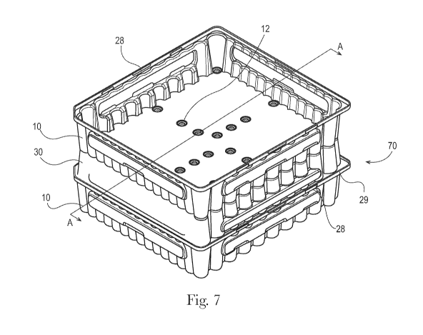
FIG. 7 is a perspective view of a storage package stack from the present
invention.
CA 3013219 2019-12-12
CA 03013219 2018-07-30
WO 2017/146893 PCT/US2017/016631
3
FIG. 7A is a sectional view along line A-A of FIG. 7.
FIG. 8 is a blown up perspective view of a storage package from the present
invention.
FIG. 9 is a perspective view of a tray from the present invention.
FIG. 10 is a perspective view of a tray stack from the present invention.
FIG. 11 is a perspective view of a cover stack from the present invention.
FIG. 12 is a close up sectional view of a tray stack from the present
invention.
DETAILED DESCRIPTION OF THE INVENTION
The present invention comprises a tray and cover for storing tubes, such as
collapsible tubes. A
tray is used to store and transport tubes, the tubes are similarly orientated
and arranged side by
side in parallel alignment, and held in position by opposing pairs of tray
sidewalls. A tray may
also be used with a cover; the cover interconnects with a tray and has one or
more indentations,
each giving rise to a corresponding protrusion shaped to project into the open
end of a tube, in
such a manner as to retain the tube in its correct position and provide
support against accidental
deformation. Each tray may also have one or more protrusions, each protrusion
being shaped to
project into one or more indentations present on a cover upon which the tray
is stacked.
As used herein, the word or when used as a connector of two or more elements
is meant to
include the elements individually and in combination; for example X or Y,
means X or Y or both.
The following figures illustrate examples of the present invention. FIG. 1 and
3 are perspective
views of a tray 10 (FIG. 3 is an inverted perspective view) according to the
invention. FIG. 4 and
5 are perspective views of a cover 30 (FIG. 5 is an inverted perspective view)
designed to
interconnect with a tray 10. A storage package 70, as shown in FIG. 6, is
formed when a tray 10
is interconnected with a cover 30 to form an interior compartment 36, for the
storage of one or
more tubes.
FIG. 1 and 3 illustrate, a tray 10 which is of rectangular or square outline
corresponding to the
size and shape required by tube filling machinery, while the height of a tray
corresponds to the
CA 03013219 2018-07-30
WO 2017/146893 PCT1US2017/016631
4
length of the tubes being transported. A tray 10 has a bottom wall 21 and two
pairs of opposing
side walls 22, 24 and 23, 25. A tray 10 is rectangular or square in plan and
is sized so that a
cover 30 may be interconnected with it to define an interior compartment 36,
as shown in FIG. 6.
In the embodiment shown in FIG. 6 the cover 30 is intended to nest within the
tray 10, although
other embodiments of the present invention may reverse the relationship. The
tray is made, for
example by vacuum moulding, from rigid or semi-rigid thin plastic sheet
material; the sheet
material may be opaque, translucent, or transparent, and as seen from above
comprises, as shown
in FIG. 1 and 3, a substantially flat bottom wall 21, with one or more
protrusions 12 that may be
organized in any fashion, such as in rows. A tray may comprise one or more of
the following
materials, such as acrylonitrile butadiene styrene, polyvinyl chloride, high
impact polystyrene,
polyethylene terephthalate, polycarbonate, acrylic, or high density
polyethylene. The sidewalls
22, 23, 24 and 25 are formed integrally with the bottom wall 21 and extend
upwardly from it.
The protrusions 12 are shaped, so as to have a base 14 which is semi-circular
or circular in
horizontal cross section. Extending away from the base 14 and in opposite
direction from the
sidewalls 22, 23, 24 and 25; and in certain embodiments in the same or similar
horizontal cross
section as the base 14, is a frusto-conical portion 16 which may be closed at
its distal end 18.
A protrusion 12, as shown in FIG. 3, 7 and 7A may be shaped to complement
(when two or more
storage packages 70 are stacked on top of each other, or as shown in FIG. 7
and 7A when a tray
10 is stacked on top of the cover 30 of a storage package 70) a corresponding
indentation 40 on
the top wall 31 of a corresponding cover 30, and the shape of the indentations
40 is such that at
least a portion of a protrusion 12 fits within the indentation 40. Such a
complementary tit
between a protrusion 12 and indentation 40 allows for the stacking of two or
more storage
packages 70 and forms a stable platform by substantially reducing the lateral
movement of the
storage packages 70.
As shown in FIG. 2 and 7A, a protrusion 12 may also have a reverse frusto-
conical portion 17
extending in the opposite direction from the frusto-conical portion 16, so end
portion 15 of the
reverse frusto-conical portion 17 is substantially flush with the bottom wall
21 of the tray.
Further, the protrusions 12 are positioned on the bottom wall 21, such that
the closed end of a
tube 13A, such as a toothpaste cap, rests on the end portion 15 of a reverse
frusto-conical portion
17, thereby allowing the tubes 13 positioned over protrusions 12 to have
substantially the same
CA 03013219 2018-07-30
WO 2017/146893 PCT1US2017/016631
height as tubes 13 not positioned over protrusions 12, which reduces the
chance of tubes being
out of position or snagged and deformed during the tube filling process.
FIG. 4 and 5 show a cover 30 which has a rectangular or square outline to
complement the size
5 and shape of a tray 10, so as to be inter-connectable and form an
interior compartment. A cover
30 has a top wall 31 and two pairs of opposing side walls 32, 34 and 33, 35,
integrally formed
with the top wall 31 and extending downwardly from it, as shown in FIG. 4. The
cover is made,
for example by vacuum moulding, from rigid or semi-rigid thin plastic sheet
material; the sheet
material may be opaque, translucent, or transparent, and as seen from above
(FIG. 5) comprises a
substantially flat top wall 31, with one or more protrusions 42 that may be
organized in any
fashion, such as in rows. A cover may comprise one or more of the following
materials, such as
acrylonitrile butadiene styrene, polyvinyl chloride, high impact polystyrene,
polyethylene
terephthalate, polycarbonate, acrylic, or high density polyethylene. The
protrusions 42 are
shaped, so as to have a base 44 which is semi-circular or circular in
horizontal cross section.
Extending away from the base 44 in the same direction as the sidewalls 32, 33,
34 and 35; and in
certain embodiments having the same or similar horizontal cross section as the
base 44, is a
frusto-conical portion 46 which may be closed at its distal end 48. As shown
in FIG. 7A, a
protrusion 42 may be shaped such that the base 44 and/or the frusto-conical
portion 46 will
project within an open end 13B of a tube 13, such as a toothpaste tube, to be
carried in the
storage package 70, thus serving not only to orient the open end 13B of the
tube 13 in its correct
position in the interior compartment 36, but also to give the open end 13B of
the tube 13 some
protection against distortion or collapse. Opposite the protrusions 42 along
the top wall 31 are
one or more indentations 40 (FIG. 4 and 7A). As noted previously, the shape of
the indentations
40 is such that at least a portion of a tray protrusion 12 fits within an
indentation 40. Such a
complementary fit between a protrusion 12 and indentation 40 allows for the
stacking of two or
more storage packages 70 and forms a stable platform by substantially reducing
the lateral
movement of the storage packages 70, as shown in FIG. 7.
A tray 10, cover 30 or both may have one or more arcuate recesses 50, 51
respectively, extending
into the periphery of the tray 10 or cover 30, as shown in FIG. 1 and 5. Each
recess is sized to
receive a curved side portion of a tube 13. The recesses 50, 51 engage the
curved side portion of
a tube 13. The recesses 50, 51 control and maintain the alignment and position
of the tubes 13
CA 03013219 2018-07-30
WO 2017/146893 PCT1US2017/016631
6
within the interior compartment 36, minimizing any shifting or tilting of the
tubes 13 during
transport or storage.
A tray 10 may also comprise a stabilizer 54, as shown in FIG. 8 and 9. A
stabilizer 54 is an
.. essentially flat component that is either square or rectangular in plan, so
as to nest around the
periphery of the tray 10, although in certain embodiments of the present
invention a stabilizer
may nest in the cover or both the cover and tray. The stabilizer has one or
more arcuate recesses
53 along its inner edge 55. Each recess 53 is sized to receive a curved side
portion of a tube 13.
The recesses 53 engage the curved side portion of a tube 13. The stabilizer 54
functions to
.. prevent tubes from tipping when a tray or storage package is positioned at
an angle, for example
when a tray is loaded into a tube filling process. A stabilizer is
particularly useful when the sides
of a tray, cover or both are outwardly angled; so as to create an increasing
gap between a tube
wall and the side wall the further the tube extends away from the tray bottom
wall or the cover
top wall. A stabilizer may be formed from one or more of the following
materials, such as
acrylonitrik butadiene styrene, polyvinyl chloride, high impact polystyrene,
polyethylene
terephthalate, polycartxmate, acrylic, or high density polyethylene.
As noted above, and shown in FIG's 1 and 3-5 the sidewalls of the tray 22, 23,
24 and 25, the
sidewalls of the cover 32, 33, 34 and 35, or both may be outwardly flared from
the bottom wall
21 and top wall 31 respectively. The outward flare of the side walls allows
the trays to be
stacked 80. as shown in FIG. 10 and the covers to be stacked 90, as shown in
FIG. 11. Further,
as shown in FIG. 10, in a tray 10, at the intersection of two adjacent arcuate
recesses 50 a ridge
52 is formed. One or more of the ridges 52 may have notched ridges 54; in
certain embodiments
each side wall 22, 23, 24 and 25 would have one or more notched ridges. The
notched ridges
prevent trays or covers from getting stuck together when stacked (inducing
vacuum). It should
be noted that while FIG. 10 shows notched ridges in a tray, notched ridges may
also be present in
a cover.
The tray side walls 22, 23, 24 and 25 or cover side walls 32, 33, 34 and 35 at
their edges may be
turned outward to form a tray flange 27 or a cover flange 37, as shown in
FIG's 10 and 11. A
flange serves to reinforce the tray or cover and defines a bumper for contact
with adjacent cases.
In addition, as the flange is at the edge of the tray or cover it can provide
a hand grip for lifting.
Further, the outer edge of the flange 27 may also extend vertically to form a
lip 29. A lip 29
CA 03013219 2018-07-30
WO 2017/146893 PCT/US2017/016631
7
serves to hold a complementary tray or, as shown in FIG. 6, a cover 30 in
place such that the
complementary tray or cover is prevented from lateral or vertical movement
that would
disassociate the complementary tray or cover, which is especially important
during transportation
of the storage packages. In certain embodiments the flange and lip are
dimensioned to accept a
complementary flange, such that the complementary flange nests within the
flange and lip, as
shown in FIG. 6. While FIG. 6 shows the tray 10 having a flange 27 and lip 29,
with a cover
flange 37 nesting within the tray flange 27 and lip 29, it is still within the
scope of the present
invention for a cover to also have a flange and lip. Further, as shown in FIG.
6 and 7 a lip 29
may have one or more grooves 28, which inwardly extend from the lip 29 towards
the interior
compartment 36 a sufficient distance such that when a cover 30 is nested
within a tray 10 it is
secured; in that the cover flange 37 can pass over the one or more grooves 28,
yet the grooves 28
can prevent the cover 30 from being unsecured from the tray 10 absent the
application of some
outside force, such as by a human or machine.
FIG. 6 shows a tray or cover may have one or more tray bars 18 or cover bars
38, respectively.
The tray bars 18 and cover bars 38 function to strengthen the tray 10 and the
cover 30_ Each of
the tray bars and cover bars are integral with their respective side wall and
extend outwardly
therefrom and along the length of the side wall. In addition to their function
of strengthening the
tray and cover, bars 18, 38 enable a machine to use suction cups or some other
type of "end
affector" to grab the trays, covers, or both. Further, when trays or covers
are stacked; in this
instance trays 10A, 10B, as shown in FIG. 12 the bottom edge 19 of a side bar
18 can rest on a
flange 27 to prevent a tray 10A from becoming fully nested in another tray
10B, thereby reducing
the chance of forming a vacuum and reducing surface area contact between the
trays 10A, 10B;
making it easier to separate stacked trays.
Tubes generally begin the tube filling process having an open end and a closed
end, with the
open end being exposed for the filling of the tube. In certain embodiments
tubes, for example
collapsible tubes may be formed from aluminum or of other flexible metal or
plastic, and consist
of a sleeve-like body which can be deformed to express the contents of the
tube, the body having
at one end a shoulder of rather heavier material, which terminates in a
central neck to which a
cap may be removably secured. Such collapsible tubes, after manufacture,
normally have a cap
applied to them thereby creating a closed end and an open end from which the
tube may be filled.
CA 03013219 2018-07-30
WO 2017/146893 PCT/US2017/016631
8
A. A tray for holding one or more tubes comprising a tray which is of
rectangular or square
outline having; a substantially flat bottom wall including one or more
protrusions; the
protrusions having a base and a frusto-conical portion; sidewalls; wherein at
least one
sidewall has an arcuate recess.
B. The tray of paragraph A wherein the one or more protrusions are closed
at their distal
end.
C. The tray of paragraph A or B wherein the protrusions comprise one or
more reverse
frusto-conical portions, preferably wherein the one or more reverse frusto-
conical-
portions have an end portion that is substantially flush with the bottom wall.
D. The tray according to any of paragraphs A to C wherein the sidewalls
outwardly flare
from the bottom wall, preferably wherein the tray comprises a stabilizer which
is shaped
to nest around the periphery of the tray, more preferably wherein the
stabilizer has an
inner edge comprising one or more arcuate recesses.
E. The tray according to any of paragraphs A to D wherein the sidewalls
have at least one
notched ridge.
F. A storage package for holding one or more tubes comprising a tray which
is of
rectangular or square outline having; a substantially flat bottom wall
including one or
more protrusions; the protrusions having a base and a frusto-conical portion;
sidewalls,
wherein at least one sidewall has an arcuate recess; a cover which is of
rectangular or
square outline that is inter-connectable with the tray to form an interior
compartment
having; a substantially flat top wall including one or more protrusions;
sidewalls, wherein
at least one sidewall has an arcuate recess.
G. The storage package of paragraph F wherein the tray protrusions comprise
one or more
reverse frusto-conical portions, preferably wherein the one or more reverse
frusto-
conical-portions have an end portion that is substantially flush with the
bottom wall.
CA 03013219 2018-07-30
WO 2017/146893 PCT/US2017/016631
9
H. The storage package of paragraph G comprising one or more tubes having
an open and
closed end, the tubes being similarly oriented arranged side by side,
preferably wherein
the one or more tubes are held in position at the closed end by the bottom
wall and
reverse frusto-conical end portions, at the open end by a corresponding cover
protrusion,
each protrusion being shaped to project into the open end of the tube, and
along the side
of the tubes by the cover and tray arcuate recesses.
The storage package according to paragraph G wherein the tray sidewalls
outwardly flare
from the bottom wall and the cover sidewalls outwardly incline from the top
wall,
preferably wherein the tray comprises a stabilizer which is shaped to nest
around the
periphery of the tray, more preferably wherein the stabilizer has an inner
edge comprising
one or more arcuate recesses.
J. The storage package of paragraph I comprising one or more tubes having
an open and
closed end, the tubes being similarly oriented arranged side by side,
preferably wherein
one or more tubes are held in position at the closed end by the bottom wall
and reverse
frusto-conical end portions, at the open end by a corresponding cover
protrusion, each
protrusion being shaped to project into the open end of the tube, and along
the side of the
tubes by the stabilizer inner edge arcuate recesses.
K. The storage package of paragraph F, wherein the tray sidewalls comprise
a flange and lip
and the cover sidewalls comprise a flange that is nested within the tray
flange and lip,
preferably wherein the tray lip comprises a groove.
L. A stack of storage packages comprising a top storage package and a
bottom storage
package each of which comprise a tray which is of rectangular or square
outline having; a
substantially flat bottom wall including one or more protrusions; the
protrusions having a
base and a frusto-conical portion; opposite each protrusion is a reverse
frusto-conical
portion; sidewalls, wherein at least one sidewall has an arcuate recess; a
cover which is of
rectangular or square outline that is inter-connectable with the tray to form
an interior
compartment having; a substantially flat top wall including one or more
protrusions;
opposite each protrusion is an indentation; sidewalls, wherein at least one
sidewall has an
arcuate recess; wherein the top storage package is stacked on the bottom
storage package,
10
such that the tray protrusions of the top storage package fit within
complementary
indentations on the bottom storage package cover.
The dimensions and values disclosed herein are not to be understood as being
strictly limited to
the exact numerical values recited. Instead, unless otherwise specified, each
such dimension is
intended to mean both the recited value and a functionally equivalent range
surrounding that
value. For example, a dimension disclosed as "40 mm" is intended to mean
"about 40 mm."
While particular embodiments of the present invention have been illustrated
and described, it
would be obvious to those skilled in the art that various other changes and
modifications can be
made without departing from the spirit and scope of the invention. It is
therefore intended to
cover in the appended claims all such changes and modifications that are
within the scope of
this invention.
CA 3013219 2019-12-12