Note: Descriptions are shown in the official language in which they were submitted.
WO 2012/106592 PCT/US2012/023757
-1-
MOLYBDENUM DISULFIDE POWDERS AND
METHODS AND APPARATUS FOR PRODUCING THE SAME
Technical Field
The present invention generally relates to the processing of molybdenum and
more
particularly to the production of molybdenum disulfide powders.
Background Art
Molybdenum disulfide (MoS2) is usually recovered from molybdenite ore obtained
from a
variety of mine sites, including "primary" and "secondary" and mine sites.
Broadly speaking,
molybdenite ore consists of silicified granite compositions having deposits of
soft, black, and
hexagonal MoS2 crystalline structures widely dispersed therein (e.g., in an
average concentration
of only about 0.03 - 0.6% by weight of the entire ore body). One of the
largest sources of MoS2-
containing ore (e.g., molybdenite) is the Henderson molybdenum mine near
Empire, CO (US),
currently operated by the Climax Molybdenum Company, although other mine sites
throughout the
world are able to produce large amounts of this material as well. The
Henderson mine site is
characterized as a primary mine and is capable of producing large amounts of
molybdenite ore.
Molybdenum disulfide also may be recovered from secondary or by-product
molybdenite
obtained from secondary mine sites. For example, secondary molybdenite may be
obtained from
copper mines, wherein the secondary molybdenite is typically combined with
copper-containing
materials (e.g., copper sulfide). In such cases, molybdenum disulfide
concentrate is obtained as a
by-product from copper sulfide-molybdenum disulfide separation processes.
In a typical processing operation, the molybdenite ore is initially subjected
to a physical
grinding process in which the ore is reduced in size to a plurality of small
particles (e.g., having a
typical particle size of about 100 U.S. mesh or less). The ore particles are
then further treated to
remove the desired MoS2 therefrom. This treatment step may be accomplished
using a variety of
techniques, including froth flotation extraction procedures that employ
various hydrocarbon
compositions and wetting agents known in the art for this purpose. As a
result, the desired MoS2
may be effectively separated from ore-based waste materials (i.e., "gangue"),
such as silica,
silicates, clays, and other unwanted materials. The desired MoS2 compositions
will, by virtue of
their minimal weight and density levels compared with the gangue, be readily
isolated in the
flotation froth.
The resulting molybdenum disulfide concentrate (i.e., from either primary or
non-primary
CA 3013250 2018-08-02
WO 2012/106592 PCT/US2012/023757
-2-
sources, as noted above) may be dried and sized (e.g., by grinding and
subsequent classification
steps) to produce a molybdenum disulfide powder product having the desired
grade and particle
size. Exemplary grades of molybdenum disulfide include "technical," "technical
fine," and
"superfine" grades, although other grades are known and commercially
available. Technical grades
of molybdenum disulfide typically comprise about 98% (by weight) molybdenum
disulfide, with
the balance comprising various amounts of iron, molybdenum trioxide, water,
oil, and carbon,
depending on a variety of factors.
The particle sizes of the molybdenum disulfide powder product may also vary
within a
specified grade. For example, technical grade molybdenum disulfide powders may
have median
particle sizes in the range of about 15-20 pm, with a small percentage of
particles being as large as
200 p.m or so. Technical fine grades may have median particle sizes in the
range of about 4-6 p.m,
whereas superfine grades may comprise median particle sizes in the range of
about 0.9 to about 1.6
Molybdenum disulfide powder products may also be characterized by an "acid
number" and
by an "oil number." The acid number of molybdenum disulfide typically refers
to the amount or
quantity of a base, such as potassium hydroxide (KOH), required to neutralize
the acid in a defined
quantity of molybdenum disulfide. The acid number is typically expressed as an
absolute value and
is the number of milligrams (mg) of potassium hydroxide (KOH) required to
neutralize the acid in
a 1-gram sample of molybdenum disulfide.
The acid number of a molybdenum disulfide product may vary from producer-to-
producer
and also tends to vary with particle size within a given grade. Generally
speaking, the acid number
increases with decreasing particle size. Thus, a plain technical grade
molybdenum disulfide will
typically have the lowest acid number, with the technical fine and superfine
grades having
progressively higher acid numbers.
The oil number is a measure of the residual oils contained in the molybdenum
disulfide
powder product. The residual oils may originate from a variety of sources,
including the various
froth flotation steps used during ore beneficiation, as well as from oils
added to the molybdenum
disulfide during various grinding or milling processes required to reduce the
molybdenum disulfide
powder product to the desired particle size. The oil number is typically
expressed as a weight
percentage of oil contained in the molybdenum disulfide powder product.
Depending on the ultimate application or use of the molybdenum disulfide
powder product,
it may be desirable or advantageous to reduce the acid number and/or oil
number as much as
possible. While various processes are known and may be used to reduce the acid
and/or oil
CA 3013250 2018-08-02
WO 2012/106592 PCT/US2012/023757
-3-
numbers, such processes typically involve additional processing steps, thus
additional time and
processing expense, before the molybdenum disulfide product will have the
desired acid and/or oil
numbers. Consequently, methods continue to be sought that will provide for the
effective control
of the acid and/or oil numbers in the molybdenum disulfide product while
minimizing the need for
additional time or process steps to achieve the desired product
specifications.
Disclosure of Invention
A molybdenum disulfide powder product produced by jet milling a molybdenum
disulfide
precursor material and substantially continuously combining newly sized-
reduced particles with oil
to produce said molybdenum disulfide powder product, said molybdenum disulfide
powder product
having a D50 particle size of less than 4 p.m and an acid number that is less
than about 0.5 mg
KOH/g.
Also disclosed is a molybdenum disulfide powder product produced by jet
milling a
molybdenum disulfide precursor material in an oil-containing atmosphere so
that newly exposed
surfaces of size-reduced particles are coated with oil during substantially
the entirety of the jet
milling process.
A method for producing a powder product may involve the steps of: Providing a
supply of
a precursor powder material; accelerating particles of the precursor powder
material by combining
them with a flow of gas; confining the accelerated particles in a milling
chamber so that they collide
with one another to effect a size reduction; and coating newly exposed
surfaces of size-reduced
particles with oil.
Apparatus for reducing a particle size of a precursor powder material by fluid
energy impact
according to one embodiment of the invention may include a housing defining an
interior milling
cavity therein having a peripheral wall. A powder feed inlet operatively
associated with the housing
allows the precursor powder material to be introduced into the interior
milling cavity. A product
discharge outlet operatively associated with the housing allows a milled
powder product to be
removed from the interior milling cavity. An oil injection nozzle assembly
operatively associated
with the product discharge outlet injects oil into a particle-laden product
stream from the product
discharge outlet.
Another embodiment of apparatus for reducing a particle size of a precursor
powder material
by fluid energy impact may include a housing defining an interior milling
cavity therein having a
peripheral wall. A powder feed inlet operatively associated with the housing
allows the precursor
powder material to be introduced into the interior milling cavity. A product
discharge outlet
CA 3013250 2018-08-02
WO 2012/106592 PCT/US2012/023757
-4-
operatively associated with the housing allows a milled powder product to be
removed from the
interior milling cavity. An oil feed inlet operatively associated with the
housing allows an oil to be
introduced into the interior milling cavity of the housing.
Brief Description of the Drawings
Illustrative and presently preferred embodiments of the invention are shown in
the
accompanying drawings in which:
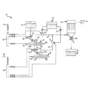
Figure 1 is a schematic representation of various components and material
pathways that
may be utilized in one embodiment of the present invention to produce
molybdenum disulfide
particles;
Figure 2 is a side view in elevation of one embodiment of jet mill apparatus
with a portion
of the housing broken away to show the interior milling chamber;
Figure 3 is a top view of the jet mill illustrated in Figure 2 with a portion
of the housing
broken away to show the interior milling chamber;
Figure 4 is a side view in elevation of one embodiment of a tandem jet mill
that may be used
to produce molybdenum disulfide particles; and
Figure 5 is a schematic representation of various components and material
pathways that
may be utilized in another embodiment of the present invention to produce
molybdenum disulfide
particles.
Best Mode for Carrying Out the Invention
Apparatus 10 for producing a molybdenum disulfide powder product 12 having a
reduced
acid number is illustrated in Figure 1 and may comprise at least one fluid
energy impact mill or "jet"
mill 14 suitable for reducing the particle size of a molybdenum disulfide
precursor powder material
16 via a fluid energy impact process. In one embodiment, jet mill 14 is
operatively connected to
a supply of pressurized process gas 18 that provides the energy required for
the fluid energy impact
process (i.e., particle size reduction). Process gas 18 also serves as a
carrier medium for the various
powder components (e.g., the final powder product 12 and powder precursor
material 16) being
processed by apparatus 10. A product collection apparatus 22 operatively
connected to a discharge
port or outlet 24 of jet mill 14 separates the powder product 12 from the
"carrier" process gas 18.
Apparatus 10 may also comprise a supply of oil 20 that may be injected or
combined with
newly size-reduced particles at various points in the apparatus 10. For
example, in the embodiment
illustrated in Figure 1, the oil 20 may be injected into the particle stream
at one or more locations
CA 3013250 2018-08-02
WO 2012/106592 PCT/US2012/023757
-5-
downstream from the jet mill 14. This type of oil injection may be referred to
herein in the
alternative as "post-milling oil injection." Alternatively, other embodiments
may inject the oil 20
at one or more locations upstream from the mill 14 (referred to herein in the
alternative as "pre-
milling oil injection"). Still other embodiments may involve both pre- and
post-milling oil
injection. See Figure 5.
The oil 20 is added to coat the newly-exposed surfaces of the size-reduced
particles in order
to reduce the acid number of the final powder product 12. In addition, in an
embodiment involving
pre-milling oil injection, such as that illustrated in Figure 5, the oil 20
may also function to lubricate
and/or cool the particles during the milling process. Pre-milling oil
injection also allows the oil 20
to continuously coat the particles during the milling or size reduction
process so that newly-exposed
surfaces of the size-reduced particles are substantially continuously coated
with oil 20 during the
milling process. Post-milling oil injection coats the particles with oil
immediately following the
milling process, before they reach the product collection apparatus 22.
In some embodiments, the apparatus 10 may be provided with a second fluid
energy impact
or jet mill 26 to process additional quantities of the precursor powder
material 16. See Figures 1
and 4. In such an embodiment, the second jet mill 26 may be operatively
connected to a product
"underflow" outlet 28 of first jet mill 14 so that the second jet mill 26
receives additional quantities
of the precursor powder material 16 from the first mill 14. The second jet
mill 26 may also be
connected to a supply of pressurized process gas 30 which, in one embodiment,
may be the same
as the process gas supply 18 used for the first jet mill 14. See Figure 1. A
product discharge port
32 of second jet mill 26 is also operatively connected to product collection
apparatus 22. In such
an embodiment, then, the final powder product 12 will comprise a combination
of milled powders
from both the first mill 14 and the second mill 26. In an embodiment involving
a second jet mill
26, it may be desirable or advantageous to inject oil 20 at one or more
locations downstream from
the second jet mill 26, as also shown in Figure 1.
Referring now primarily to Figures 1-3, the apparatus 10 may be operated as
follows to
produce the molybdenum disulfide powder product 12 from the precursor powder
material 16. A
first step in the process may involve the provision of a suitable precursor
material 16. In an
embodiment wherein the final powder product 12 is to comprise a molybdenum
disulfide (MoS2)
powder having a reduced acid number, the precursor powder material 16 may also
comprise a
molybdenum disulfide powder. However, the molybdenum disulfide precursor
powder material 16
will typically comprise particles that are larger than the particles
comprising the final powder
product 12.
CA 3013250 2018-08-02
WO 2012/106592 PCT/US2012/023757
-6-
For example, in an embodiment wherein the final molybdenum disulfide powder
product
12 is to comprise particles having sizes in the range typically associated
with a superfine grade of
molybdenum disulfide (e.g., particles having a median or "D50" particle size
in a range of about
0.9 gm to about 1.6 gm), the molybdenum disulfide precursor powder material 16
may comprise
particles in a range typically associated with a technical grade of molybdenum
disulfide (e.g.,
particles having a median or D50 particle size in a range of about 16 gm to
about 30 gm).
Alternatively, of course, final powder products 12 and precursor materials 16
comprising other
particle sizes may also be used with and/or made by the present invention, as
would become
apparent to persons having ordinary skill in the art after having become
familiar with the teachings
provided herein. Consequently, the present invention should not be regarded as
limited to materials
having any particular particle size or range of particle sizes. Also, and as
will be described in
further detail herein, in some embodiments, the precursor material 16 may be
mixed with small
quantities of oil in advance of milling.
The molybdenum disulfide precursor material 16 may be provided to first jet
mill 14 via a
powder feed inlet 34, as best seen in Figure 1. In the particular embodiments
shown and described
herein, powder feed inlet 34 ofj et mill 14 is also operatively associated
with a feed gas inlet 36 that
is connected to the supply of pressurized process gas 18. In such an
arrangement, the precursor
powder material 16 is combined with the process (or feed) gas 18 before being
introduced into an
interior milling cavity 38 of jet mill 14, as a particle-laden material feed
stream 40. See Figures 2
and 3.
In the particular embodiment shown in Figure 1, pressurized process gas 18 is
also fed into
jet mill 14 via a wall gas inlet 44. Wall gas inlet 44 carries or distributes
the process gas 18 to a
plurality of nozzles 46, each of which discharges the process gas 18 at high
speed into the interior
milling cavity 38 of jet mill 14 as a wall gas stream 42. See Figures 2 and 3.
As the particle-laden material feed stream 40 enters the interior milling
cavity 38 it is rapidly
accelerated to a high velocity by the wall gas stream 42 discharged by the
various nozzles 46. The
particles comprising the precursor material 16, which are now traveling at
high speed, are ground
or size-reduced in the interior milling cavity 38 of jet mill 14 by a process
commonly referred to as
fluid energy impact. In such a process, the particle size reduction is the
result of high-velocity
collisions among the particles of the precursor powder material 16 itself. No
grinding media are
involved. As this grinding or milling process continues, the size-reduced
particles naturally migrate
toward the centrally-located product discharge port 24 provided in the jet
mill 14, whereupon they
exit the jet mill 14 as particle-laden product stream 48. The particle-laden
product stream 48
CA 3013250 2018-08-02
WO 2012/106592 PCT/US2012/023757
-7-
ultimately reaches the product collection apparatus 22, which separates the
final powder product
12 from the carrier gas 18, as best seen in Figure 1.
In the particular embodiment shown in Figure 1 (i.e., comprising first and
second jet mills
14 and 26 arranged in tandem), additional quantities of the precursor powder
material 16, i.e.,
contained in the particle-laden material feed stream 40, are fed into the
second jet mill 26 via the
underflow outlet 28 provided in first jet mill 14. More specifically, the
precursor material 16
contained in a product underflow stream 43 (Figure 2) exiting the first jet
mill 14 via the underflow
outlet 28 is ground or size-reduced in the second mill 26 in substantially the
same manner as in the
first jet mill 14. The size-reduced particles exit the second jet mill 26 via
the product discharge port
32 as particle-laden discharge stream 48'. The particle-laden discharge stream
48' from the second
jet mill 26 may be combined with the particle-laden product stream 48 from the
first mill 14 before
reaching the product collection apparatus 22. Alternatively, the two discharge
streams 48 and 48'
need not be combined before reaching the product collection apparatus 22.
As briefly described above, in embodiments involving post-milling oil
injection, oil 20 may
be injected into the particle laden discharge stream 48 from the jet mill 14.
If two jet mills are
involved, oil 20 may be injected into the particle laden discharge streams 48
and 48' from either one
or both jet mills 14 and 26. Whether oil 20 is injected into the particle-
laden discharge streams 48
and 48' from either one or both jet mills 14 and 26 will depend on a wide
range of factors, including
the expected material flows from the jet mills, the amount of oil 20 to be
injected in either stream,
whether pre-milling oil injection is used, and whether any oil is combined
with the precursor
material 16 in advance of milling. Generally speaking the total amount of oil
20 (e.g., on a weight
percentage basis) that may be added to the milled particles to achieve certain
acid and oil number
specifications may be about the same in any particular set-up. The total
amount of added oil 20 may
be divided among/between the various oil addition or injection points. Thus,
embodiments
involving pre-milling oil injection may involve reduced amounts of post-
milling oil injection than
might otherwise be the case. Similarly, if a majority of the milled particles
is produced by the first
jet mill 14, then most or all of the post-milling oil 20 may be injected into
the particle laden
discharge stream 48 from the first jet mill 14. Conversely, if a majority of
the milled particles is
produced by the second jet mill 26, then most or all of the post-milling oil
20 may be injected into
the particle laden discharge stream 48' from the second jet mill 26. In still
yet another variation,
post-milling oil 20 may be injected into the particle laden discharge streams
48 and 48' from both
jet mills 14 and 26 in embodiments wherein both jet mills 14 and 26 produce
about the same
amount of milled particles.
CA 3013250 2018-08-02
WO 2012/106592 PCT/1JS2012/023757
-8-
After exiting the jet mill or mills 14, 26, after being combined with oil 20
(e.g., in post-oil
injection embodiment), the particle-laden product stream(s) 48 and 48' from
the mill(s) 14 and 26
may be directed to the product collection apparatus 22 which separates the
final molybdenum
disulfide powder product 12 from the process gas 18.
In one embodiment, the molybdenum disulfide powder product 12 may comprise a
median
or D50 particle size in a range of about 0.9 pin to about 1.6 vin with an acid
number of less than
about 0.5 mg KOH/g, and more typically less than about 0.3 mg KOH/g. Stated
another way, the
molybdenum disulfide powder product 12 of the present invention comprises a
"superfine" grade
(i.e., based on median particle size), but having an acid number that is
considerably lower, by about
an order of magnitude, compared with acid numbers typically associated with
conventionally-
available superfine molybdenum disulfide grades. However, the oil number of
the molybdenum
disulfide powder product 12 is about the same as the oil numbers of
conventionally available
superfine molybdenum disulfide grades.
A significant advantage of the present invention is that it provides a method
and apparatus
for producing a molybdenum disulfide powder product having an acid number that
is considerably
lower than the acid numbers of conventionally available powder materials of
the same grade. For
example, superfine grades of molybdenum disulfide powder product material 12
produced in
accordance with the teachings of the present invention typically comprise an
acid number of less
than about 0.5 mg KOH/g (more typically less than about 0.3 mg KOH/g), which
is considerably
lower than the acid number associated with conventionally-available superfine
grades of
molybdenum disulfide, which is on the order of about 3 mg KOH/g. Moreover, the
present
invention achieves such a substantial reduction in acid number without a
corresponding increase
in the oil number of the final powder product.
As is known, the acid number represents the degree of surface oxidation of the
molybdenum
disulfide particles. The degree of oxidization, as measured by the acid
number, is of considerable
practical importance in the production and use of molybdenum disulfide.
Characteristics and
factors that are influenced by the oxidation behavior of molybdenum disulfide
include, but are not
limited to, product shelf life, corrosion factors (e.g., when in contact with
other materials), film life,
friction coefficient, gelling capabilities, and break-down temperature, to
name a few.
Still other advantages are associated with the oil injection processes
associated with the
present invention. For example, in conventional molybdenum disulfide
processing, oil is typically
mixed with the molybdenum disulfide feed material before the material is
ground in a jet mill. The
mixing process typically involves feeding a defined quantity of molybdenum
disulfide feed material
CA 3013250 2018-08-02
WO 2012/106592 PCT/US2012/023757
-9-
and oil into a mixing drum or chamber. The oil and molybdenum disulfide are
then mixed together
in the drum for some defined period of time in order to ensure that the oil is
thoroughly mixed with
the molybdenum disulfide. After being mixed, the material is then fed into the
jet mill for grinding.
This conventional process for producing a molybdenum disulfide powder product
is less
than optimal, in that it involves both batch and continuous processes in the
same production line
or sequence. The mixing of batch and continuous processes in a single
production line is less than
ideal in many respects and represents inefficiencies and sub-optimal use of
materials and resources.
In contrast with this conventional process, the present invention may dispense
with the need to first
coat the molybdenum disulfide precursor material with oil before it is fed
into the jet mill, thereby
eliminating the process steps, equipment, and time associated with the oil
coating process.
Having briefly described basic embodiments of the invention, as well as
several of its more
significant features and advantages, various exemplary embodiments of methods
and apparatus for
producing the various powder products will now be described in detail.
However, before
proceeding with the description it should be noted that while the various
embodiments are described
herein as they could be used to produce a superfine grade of molybdenum
disulfide (i.e., having a
median or DSO particle size in the range of about 0.9 um to about 1.6 um)
having an acid number
of less than about 0.3 mg KOH/g, the methods and apparatus of the present
invention could be used
to produce a molybdenum disulfide powder product 12 having other particle
sizes, commensurate
with other commonly specified grades. Moreover, it should be noted that the
present invention is
not limited to the production of molybdenum disulfide powders, and could be
used instead to
produce other kinds of powders, and particularly coated particles, from other
kinds of precursor and
coating materials. Consequently, the present invention should not be regarded
as limited to the
particular products, materials, and applications shown and described herein.
Referring back now to Figures 1-3, one embodiment of apparatus 10 for
producing a powder
product 12, such as a superfine grade of molybdenum disulfide having a reduced
acid number, may
comprise a fluid energy impact mill or jet mill 14. Jet mill 14 may comprise a
housing 52 that
defines a generally circular interior milling chamber or cavity 38 therein
that is bounded by a
peripheral wall 54. Housing 52 ofjet mill 14 may also be provided with a
powder feed inlet 34 and
a product discharge port 24 to allow the precursor material 16 to be fed into
the jet mill 14 and to
allow the powder product 12 to be extracted therefrom.
The powder feed inlet 34 is also operatively associated with feed gas inlet
36. This
arrangement allows the precursor powder material 16 to be mixed or combined
with the feed or
process gas 18 to form particle-laden material feed stream 40. In addition,
jet mill 14 may also be
CA 3013250 2018-08-02
WO 2012/106592 PCT/US2012/023757
-10-
provided with a wall gas inlet 44. Wall gas inlet 44 allows a "wall" gas
stream 42 (e.g., comprising
process gas 18) to be injected into the interior milling chamber 38 from
points adjacent the
peripheral wall 54. In an embodiment wherein jet mill 14 is to be used in
tandem with a second jet
mill 26 (illustrated in Figures 1 and 4), the first jet mill 14 may also be
provided with an internal
cyclone collector (not shown) that is operatively associated with underflow
outlet 28. Larger (i.e.,
oversized) particles collected by the cyclone collector (not shown) internal
to the first jet mill 14
are discharged via underflow outlet 28 as underflow stream 43. See Figure 2.
Referring now primarily to Figures 2 and 3, the peripheral wall 54 of jet mill
14 may also
be provided with a plurality of nozzles 46. Each of the nozzles 46 is
fluidically coupled with the
wall gas inlet 44, e.g., via an annular plenum 66. Each of the nozzles 46
accelerates the "wall" gas
(e.g., process gas 18) provided via the wall gas inlet 44, so that the wall
gas stream 42 is discharged
into the interior milling chamber 38 at high speed. The various nozzles 46 are
angled with respect
to the peripheral wall 54 so that the wall gas stream 42 is directed in a
substantially tangential
direction within milling chamber 38. See Figure 3. The high speed wall gas
stream 42 discharged
by the nozzles 46 accelerates the precursor material 16 contained in the
particle-laden material feed
stream 40 a velocity sufficient to initiate the particle size reduction
process.
As mentioned, apparatus 10 may also comprise a second fluid energy impact or
jet mill 26,
as best seen in Figures 1 and 4. Second jet mill 26 may be used to process
additional quantities of
the precursor powder material 16 from the first jet mill 14. More
specifically, the second jet mill
26 is operatively connected to the product underflow outlet 28 of first jet
mill 14. Second jet mill
26 may also be connected to a supply of pressurized process gas 30 which, in
one embodiment, may
be the same as the process gas supply 18 used for the first jet mill 14. A
product discharge port 32
of second jet mill 26 is also operatively connected to product collection
apparatus 22. The second
jet mill 26 may be substantially similar in construction to the first jet mill
14 already described.
Consequently, the second jet mill 26 will not be described in further detail
herein.
The first and second jet mills 14 and 26 may comprise any of a wide range of
jet mill
apparatus now known in the art or that may be developed in the future that
are, or would be, suitable
for effecting a particle size reduction via the fluid energy impact process
described herein.
Consequently, the present invention should not be regarded as limited to any
particular jet mill
apparatus having any particular configuration. However, by way of example, in
one embodiment,
the first and second jet mills 14 and 26 comprise a 15-inch tandem jet mill
assembly available from
the Jet Pulverizer Company of Moorestown, NJ (US) under the trademark "Micron-
Master."
Alternatively, other types of jet mills available from other manufacturers may
be used as well.
CA 3013250 2018-08-02
WO 2012/106592 PCT/1JS2012/023757
-11-
Referring back now to Figure 1, jet mill 14 may be operatively connected to a
supply of a
precursor powder material 16. In an embodiment wherein the final powder
product 12 is to
comprise a molybdenum disulfide powder, the precursor powder material 16 may
also comprise a
molybdenum disulfide (MoS2) powder. Molybdenum disulfide powders suitable for
use in the
present invention are commercially available from Climax Molybdenum Company, a
Freeport-
McMoRan Company, Ft. Madison Operations, Ft. Madison, Iowa (US).
Alternatively, molybdenum
disulfide powders available from other sources may be used as well. By way of
example, the
molybdenum disulfide precursor material 16 comprises a technical grade of
molybdenum disulfide
powder commercially available from Climax Molybdenum Company.
The pressurized process gas 18 provided to jet mill 14 provides the energy
required for the
fluid energy particle reduction process, and also serves as a carrier medium
for the precursor powder
material 16 and the final powder product 12. In an embodiment using a second
jet mill 26, second
jet mill 26 may be operatively connected to a supply of pressurized process
gas 30, which may be
the same as the supply of pressurized process gas 18 for the first jet mill
14. As was the case for
the first jet mill 14, the pressurized process gas 30 for the second jet mill
26 provides the energy
required for the milling process and also serves as a carrier medium for the
various powders (e.g.,
the precursor powder material 16 and the final powder product 12) being
processed by apparatus
10.
As depicted in Figure 1, the pressurized process gas 18 may be provided to the
feed gas and
wall gas inlets 36 and 44 provided on jet mill 14 via a suitable distribution
manifold 58.
Alternatively, other arrangements are possible. In an embodiment using a
second jet mill 26, the
second jet mill 26 may also be connected to the supply of pressurized process
gas 30 via a
distribution manifold 60. Distribution manifold 60 is used to provide the
pressurized process gas
to respective feed gas and wall gas inlets 62 and 64 of second jet mill 26, as
also best seen in
25 Figure 1.
Process gases 18 and 30 may comprise any of a wide range of gases suitable for
the intended
application and for the particular materials involved. In one embodiment,
pressurized process gases
18 and 30 comprise dry air and are provided at pressures and flow rates
suitable for the particular
jet mill or mills involved, as well as on various other factors, as would
become apparent to persons
30 having ordinary skill in the art after having become familiar with the
teachings provided herein.
Consequently, the present invention should not be regarded as limited to use
with any particular
type of process gases 18 and 30 and delivered at any particular pressure.
Apparatus 10 may also comprise a supply of oil 20 that may be provided or
injected at any
CA 3013250 2018-08-02
WO 2012/106592 PCT/US2012/023757
-12-
of a wide variety of locations or positions downstream or upstream from the
jet mill(s) 14 and 26
in the manner described herein. In some embodiments, oil 20 may be injected at
one or more
locations downstream from the jet mill(s) 14 and 26 (i.e., in an embodiment
involving post-mill oil
injection), whereas in other embodiments, oil 20 may be injected at one or
more positions upstream
from the jet mill(s) 14 and 26 (i.e., in an embodiment involving pre-mill oil
injection). In still other
embodiments, the oil 20 may be injected at both upstream and downstream
locations.
With reference now specifically to Figure 1, in one embodiment, oil 20 may be
injected into
the particle laden product stream 48' from the second jet mill 24 by means of
a nozzle assembly 72
that is operatively associated with the discharge conduit (not shown)
connected to the product
discharge port 32 of jet mill 26. A pump 50 may be used to provide the oil 20
at a pressure
sufficient to allow the oil 20 to be sufficiently atomized by nozzle assembly
72 so that the oil 20
will evenly coat substantially all of the particles contained in the particle
laden product stream 48'.
Pump 50 may also include a metering device (not shown) suitable for regulating
the flow of oil 20
into the process gas stream 18 in accordance with the teachings provided
herein.
Nozzle assembly 72 may comprise any of a wide range of nozzles suitable for
atomizing the
oil 20 to a degree sufficient to provide a substantially even coating on the
particles contained in the
particle laden product stream 48'. By way of example, in one embodiment,
nozzle assembly 72 may
comprise an air atomizing nozzle in which a gas, such as air, is used to
atomize the oil 20 entering
nozzle assembly 72. If such an air atomizing nozzle is used, then nozzle
assembly 72 will need to
be connected to a suitable supply of air. In one embodiment, nozzle assembly
72 may be connected
to the supply of process gas 30 via manifold 60, as best seen in Figure 1,
although other
arrangements are possible.
It should be noted that nozzle assembly 72 need not comprise an air atomizing
nozzle, but
could comprise a high pressure or hydraulic nozzle in which the oil is
provided at high pressure to
the nozzle. If such a high pressure or hydraulic nozzle is used, then pump 50
should be capable of
supplying the oil 20 at the high pressure required for satisfactory
atomization.
As mentioned earlier, it may be desirable in certain embodiments ofthe
invention to provide
post-milling oil injection into the particle-laden product stream 48 from the
first mill 14. Such an
arrangement may be desirable or advantageous in embodiments wherein the first
jet mill 14
produces substantial quantities of milled material or on other factors, as
discussed herein. If so,
additional quantities of oil 20 could be provided via a pump 50' and nozzle
assembly 72' which may
be identical to pump 50 and nozzle 72 already described for the first oil
injection location. If nozzle
assembly 72' comprises an air atomizing nozzle, then nozzle assembly 72' may
be connected to the
CA 3 0 1 3250 2 0 1 8-0 8-0 2
WO 2012/106592 PCMS2012/023757
-13-
supply of pressurized process gas 18 via manifold 58, as best seen in Figure
1. Alternatively, a
high-pressure or hydraulic type nozzle could also be used, provided sufficient
pressure is provided
by pump 50'.
Oil 20 may comprise any of a wide range of oils that are now known in the art
or that may
be available in the future that are, or would be, suitable for the particular
precursor material 16
being utilized. Consequently, the present invention should not be regarded as
limited to any
particular type of oil. However, by way of example, in one embodiment wherein
the precursor
material 16 comprises molybdenum disulfide, the oil 20 may comprise a
paraffinic, low-viscosity
oil containing polymethlymethacrylate (as a pour point depressant), a silicone
anti-foaming additive,
and a fatty-acid ester (as a friction modifier). Such an oil 20 is available
from the American
Refining Group as "Kendex LMO."
As already described, after being combined with oil 20 the particle-laden
product stream(s)
48 discharged by jet mill 14 and, optionally, jet mill 26 (e.g., as particle-
laden product stream 48'),
are directed to a product collection apparatus 22. Product collection
apparatus 22 operates to
separate the (now oil-coated) final powder product 12 from the particle-laden
stream 48. Product
collection apparatus 22 may comprise any of a wide range of cyclone and/or
"baghouse" type
separator systems that are well-known in the art for such purposes and readily
commercially
available. Consequently, the particular product collection apparatus 22 that
may be utilized in one
embodiment of the present invention will not be described in further detail
herein.
Apparatus 10 may be operated as follows to produce a powder product 12 from a
precursor
powder material 16. However, before proceeding with the description it should
be noted that,
because of the particle size reduction process performed by the jet mill(s) 14
and 26, it will be
generally desirable to select a precursor powder material 16 having a particle
size that is larger than
that of the final powder product 12. However, the particle size of the
precursor material 16 should
not be so large as to preclude the production of a final powder product 12
having the desired particle
size. That is, the particle size of the precursor material 16 should be
selected so that the milling
process will be successful in producing a final powder product 12 having the
desired particle size.
In addition, it should be noted that, in most applications, the precursor
powder material 16 will
generally comprise the same material as the final powder product 12. However,
there may be
circumstances where the two materials may comprise different substances.
By way of example, in an embodiment wherein the final powder product 12 is to
comprise
a molybdenum disulfide (MoS2) powder, the precursor powder material 16 may
also comprise a
molybdenum disulfide powder. In the particular example embodiments described
in the
CA 3013250 2018-08-02
WO 2012/106592 PCT/US2012/023757
-14-
"Examples" section, wherein the molybdenum disulfide powder product 12 is to
comprise particles
having sizes in the range typically associated with a superfine grade of
molybdenum disulfide (e.g.,
particles having a median or D50 particle size in a range of about 0.9 m to
about 1.6 m), the
molybdenum disulfide precursor powder material 16 may comprise particles in a
range typically
associated with a technical grade of molybdenum disulfide (e.g., particles
having a median or D50
particle size in a range of about 16 pm to about 30 pm). In some embodiments,
it may be desirable
or advantageous to mix small amounts of oil with the precursor powder material
16 before the
precursor material is fed to the jet mill 14.
The molybdenum disulfide precursor material 16 is provided to first jet mill
14 via a powder
feed inlet 34, as best seen in Figure 1. Because the powder feed inlet 34 of
jet mill 14 is also
operatively associated with the feed gas inlet 36, the precursor powder
material 16 will be entrained
in the process gas 18, thus forming a particle-laden material feed stream 40.
The particle-laden
material feed stream 40 then enters the interior milling chamber 38 of jet
mill 14, as best seen in
Figures 2 and 3. During this material feed process, additional amounts of
process gas 18 are fed
into the jet mill 14 via wall gas inlet 44, whereupon it enters the interior
milling cavity 38 via the
plurality of nozzles 46 as wall gas stream 42.
As the precursor powder material 16 enters the interior milling cavity 38
(i.e., suspended
in the particle-laden material feed stream 40), the particles contained
therein are accelerated to high
velocities by the wall gas steam 42 exiting the nozzles 46. The velocity is
sufficient to initiate the
grinding or particle size reduction process. More particularly, as the
particles of the precursor
material 16 travel in a circular pattern in the interior milling chamber 38,
they collide with one
another and break apart. As the grinding or milling process continues, the
size-reduced particles
migrate toward the centrally-located product discharge port 24 provided in the
jet mill 14,
whereupon they exit jet mill 14 as particle-laden product stream 48.
In an embodiment comprising first and second jet mills 14 and 26 arranged in
tandem,
additional quantities of the precursor powder material 16, i.e., contained in
product underflow
stream 43, are fed into the second jet mill 26 via the underflow outlet 28. As
described earlier, the
product underflow stream 43 comprises a mixture of the particle-laden material
feed stream 40 and
the wall gas stream 42. The precursor material 16 contained in the underflow
stream 43 is ground
or size-reduced in the second mill 26 in substantially the same manner as in
the first jet mill 14, and
departs the second jet mill 26 via the product discharge port 32 as particle-
laden discharge stream
48'.
Depending on the particular embodiment, either one or both of the particle-
laden discharge
CA 3 0 1 3250 2 0 1 8-0 8-0 2
WO 2012/106592 PCT/US2012/023757
-15-
stream(s) 48 and 48' (i.e., comprising newly size-reduced particles) are
combined with oil 20 before
arriving at the product collection apparatus 22. In an embodiment wherein the
second jet mill 24
processes a majority of the material, then only the particle-laden discharge
stream 48' from the
second mill 24 may be combined with oil 20 from nozzle assembly 72.
Alternatively, the particle-
laden discharge stream 48 from the first mill 14 may also be combined with oil
20 from nozzle
assembly 72'. In any event, and regardless of whether either one or both
particle-laden product
streams 48 and 48' are combined with oil 20, the streams 48 and 48' are then
conducted to the
product collection apparatus 22 which separates the final powder product 12
from the process gas
18.
The molybdenum disulfide powder product 12 produced by first and second jet
mills 14 and
26 comprises a median or "D50" particle size in a range of about 0.9 p.m to
about 1.6 m with an
acid number of less than about 0.5 mg KOH/g, and more typically less than
about 0.3 mg KOH/g.
Particle size as measured by a Fisher Sub-Sieve Sizer (FSSS) is less than
about 0.6 pm and more
particularly in a range of from about 0.4 [im to about 0.45 pm, also with an
acid number of less than
about 0.5 mg KOH/g. The molybdenum disulfide powder product 12 thus comprises
a particle size
consistent with the superfine grade of molybdenum disulfide. However, unlike
conventionally
available superfine grades of molybdenum disulfide, the acid number of the
molybdenum disulfide
powder product 12 is generally considerably lower (e.g., by about an order of
magnitude), compared
to the acid numbers typically associated with conventionally-available
superfine molybdenum
disulfide grades. The oil number of the molybdenum disulfide powder product 12
is about the same
as the oil numbers of conventionally available superfine molybdenum disulfide
grades.
As mentioned earlier, other embodiments of the invention may be provided with
pre-milling
oil injection, in which the oil is provided or injected at one or more
locations upstream from the jet
mill(s). Still other embodiments may be provided with both pre-milling oil
injection and post-
milling oil injection. Moreover, an embodiment configured for both pre- and
post-milling oil
injection may be operated in either or both injection modes by selectively
activating and
deactivating the oil injection systems at the various locations.
For example, and with reference now primarily to Figure 5, another embodiment
110 of the
apparatus and method of the present invention may involve systems for
providing both pre- and
post-milling oil injection. Embodiment 110 may comprise a first jet mill 114
and a second jet mill
126 connected in tandem. As was the case for the embodiments already
described, the first mill 114
of embodiment 110 may be operatively connected to a supply of pressurized
process gas 118,
whereas the second mill 126 may be operatively connected to a supply of
pressurized process gas
CA 3013250 2018-08-02
WO 2012/106592 PCT/US2012/023757
-16-
130. The pressurized process gases 118 and 130 may comprise the same gas and
may be provided
by respective manifolds 158 and 160.
The jet mill 114 is also operatively connected to a supply of oil 120. The oil
120 provided
to jet mill 114 provides the embodiment 110 with the pre-milling oil injection
function or
operational mode. The oil 120 functions to lubricate the particles during the
milling process and
also continuously coats the particles during the milling or size reduction
process so that newly-
exposed surfaces of the size-reduced particles are substantially continuously
coated with oil during
the milling process.
Generally speaking, it will be desirable to inject or provide the oil 120 to
the jet mill 114 so
that there will be almost immediate mixing of the oil 120 with the material
being ground in the
interior milling chamber or cavity (e.g., cavity 38 of Figures 2 and 3).
Provision of the oil 120 at
points too far "upstream" from the jet mill 114, such as, for example, at a
location 172 on the
upstream end of distribution manifold 158, may result in fouling of the
manifold 158 and gas (i.e.,
air) lines with excess quantities of oil 120. Still further, it is generally
desirable to mix the oil 120
with the "wall gas" (i.e., provided to the jet mill 114 via the wall gas inlet
144) as opposed to the
"feed gas" (i.e., provided via the feed gas inlet 136). Mixing the oil 120
with the feed gas may
result in fouling or clogging of the jet mill 114 with sludge-like deposits
comprising the oil and the
powder material being processed. If a second jet mill 126 is to be provided,
it will also be desirable
to provide the oil 120 to the first mill 114 in sufficient quantities so that
there will be sufficient oil
"carry-over" to the second jet mill 126 (i.e., as a component of underflow
stream), thereby
dispensing with the need to provide additional oil 120 to the second jet mill
126.
In accordance with the foregoing considerations, then, in one embodiment, the
oil 120 is
combined with the pressurized process gas 118 at about the location of the
wall gas inlet 144 on the
jet mill 114. The resulting oil-containing process gas stream will then enter
the interior milling
chamber of jet mill 114 via the wall gas nozzles in the manner already
described for the first
embodiment. A pump 150 may be used to provide the oil 120 at a pressure
sufficient to allow it to
be mixed with the pressurized process gas 118 flowing into the wall gas inlet
144. Pump 150 may
also include a metering device (not shown) suitable for regulating the flow of
oil 120 into the
process gas stream 118 in accordance with the teachings provided herein.
Provision of the oil 120 in the manner described herein, i.e., at about the
location of the wall
gas inlet 144 ofjet mill 114, provides good results, with no oil fouling of
the air lines (e.g., carrying
the pressurized process gas 118) or the interior milling chamber or cavity of
jet mill 114. Still
further, the underflow stream (e.g., exiting jet mill 114 via underflow outlet
128) contains sufficient
CA 301 32 50 2 01 8-08-02
WO 2012/106592 PCT/US2012/023757
-17-
"carry over" oil so that additional supplies of oil 120 did not need to be
provided to the second mill
126.
The apparatus 110 may also be provided with post-milling oil injection system,
thereby
allowing the apparatus 110 to be operated in either the pre-milling oil
injection mode, the post-
milling oil injection mode, or both modes together. The post-milling oil
injection system may be
substantially identical to the system already described for the embodiment
illustrated in Figure 1
and may comprise a second oil supply 120', although first oil supply 120 could
be used for this
purpose as well. A first nozzle assembly 172 may be operatively associated
with a discharge
conduit (not shown) connected to the product discharge port 132 of second jet
mill 126. First
nozzle 172 will allow oil 120' to be combined with the particle-laden product
stream 148' produced
by the second mill 126. If desired, a second nozzle assembly 172' may be
operatively associated
with a discharge conduit (also not shown) connected to the product discharge
port 124 of first jet
mill 114. Respective pumps 150', 150" may be provided to supply the oil 120'
to the nozzle
assemblies 172, 172', as best seen in Figure 5. Nozzle assemblies 172, 172'
may also be connected
to the pressurized process gas supplies 118 and 130 via respective manifolds
158, 160, in the
manner already described for the embodiment 10 illustrated in Figure 1.
Embodiment 110 may also
be provided with a product collection apparatus 122 for separating the powder
product 112 from
the carrier process gases 118, 130.
The apparatus 110 may be operated as follows to produce the molybdenum
disulfide powder
product 112 from a precursor powder material 116. The molybdenum disulfide
precursor material
116 may be provided to the first jet mill 114 via a powder feed inlet 134,
whereupon it will be
entrained in the process gas 118 from the feed gas inlet 136.
During this material feed process, oil 120 is also provided to the jet mill
114 (i.e., in the pre-
milling oil injection process), so that the fluid energy size reduction
process occurring in the interior
chamber ofjet mill 114 is conducted in an oil-containing atmosphere. More
specifically, the oil 120
is combined with the pressurized process gas 118 just before being fed into
jet mill 114. The
resulting oil-containing process gas stream enters the jet mill 114 via wall
gas inlet 144, whereupon
it enters the interior milling cavity via a plurality of nozzles (e.g.,
nozzles 46 shown in Figures 2
and 3).
As the precursor powder material 116 enters the interior milling cavity of jet
mill 114, the
particles thereof are accelerated to a high velocity by the oil-containing
process gas steam exiting
the nozzles. The velocity is sufficient to initiate the grinding or particle
size reduction process.
More particularly, as the particles of the precursor material 116 travel in a
circular pattern in the
CA 3013250 2018-08-02
WO 2012/106592 PCT/US2012/023757
-18-
interior milling chamber, they collide with one another and break apart. As
they are reduced in size,
the newly-exposed surfaces of the broken particles are rapidly coated with oil
120 suspended in the
oil-containing process gas stream. The rapid coating of the newly-exposed
surfaces of the particles
minimizes the oxidation thereof, resulting in a significant reduction of the
acid number of the
molybdenum disulfide powder product 112.
As the grinding or milling process continues, the oil coated, size-reduced
particles migrate
toward the centrally-located product discharge port 124 provided in the jet
mill 114, whereupon
they exit jet mill 114 as particle-laden product stream 148. The particle-
laden product stream 148
is then directed to the product collection apparatus 122 which separates the
final powder product
112 from the carrier gas 118.
In an embodiment comprising first and second jet mills 114 and 126 arranged in
tandem,
as shown in Figure 5, additional quantities of the precursor powder material
116 (i.e., contained in
product underflow stream from mill 114) are fed into the second jet mill 126
via the underflow
outlet 128 ()fast mill 114. The product underflow stream comprises a mixture
of the particle-laden
material feed stream and the oil-containing process gas stream. Sufficient oil
120 remains in the
product underflow stream so that the particle size reduction process in the
second jet mill 126 is also
conducted in an oil-containing atmosphere. No additional oil 120 need be
supplied to the second
jet mill 126.
The precursor material 116 contained in the underflow stream from the first
mill 114 is
ground or size-reduced in the second mill 126 and departs the second jet mill
126 via the product
discharge port 132 as particle-laden discharge stream 148'. The particle-laden
discharge stream 148'
from the second jet mill 126 is then directed to the product collection
apparatus 122, which
separates the final powder product 112 from the process gas 118.
Post-milling oil injection may be provided by activating one or both ofthe
nozzle assemblies
172, 172' to combine additional amounts of oil 120' with the particle-laden
product streams 148,
148' from the first and second mills 114, 126, respectively. Whether any such
post-milling injection
is performed and on which particle-laden product streams 148, 148' will depend
on a wide variety
of factors, many of which are described herein and others of which would
become apparent to
persons having ordinary skill in the art after having become familiar with the
teachings provided
herein.
EXAMPLES
Post-milling Oil Injection:
Two separate milling runs or trials, referred to herein as Trials 1 and 2,
were conducted with
CA 3013250 2018-08-02
WO 2012/106592 PCT/US2012/023757
-19-
milling apparatus substantially as shown in Figure 1 and operating in the post-
milling oil injection
mode, wherein oil 20 was injected into the particle-laden product stream 48'
from the second jet mill
26 (oil 20 was not injected into the particle-laden product stream 48 from the
first jet mill 14). In
the first trial, about 2268 kg (about 5000 lbs) of precursor material 16 was
processed to yield
approximately the same quantity of final powder product 12. The precursor
powder material 16 was
pre-oiled my mixing about 5.9 kg (about 13 lbs) of oil 20 with the precursor
material 16 in advance
of milling. Twenty four (24) separate samples of the powder product 12 from
the first trial were
collected from a collection port 70 located just below a rotary valve 68
associated with the product
collection apparatus 22. See Figure 1. Each of the samples was then analyzed
for oil and acid
numbers. The results of the analyses are set forth in Table I.
The second post-milling oil injection trial (i.e., Trial 2) was basically
identical to the first
trial (i.e., Trial 1), except that the amount of oil that was mixed with the
precursor material 16 in
advance of milling was reduced to about 4.5 kg (about 10 lbs), still with
about 2268 kg (about 5000
lbs) of precursor material 16. Thirty nine (39) separate samples of the powder
product 12 from the
second trial were collected from the collection port 70. Each of the samples
was then analyzed for
oil and acid numbers. The results of the analyses are set forth in Table II.
The operational parameters for Trials 1 and 2 were basically identical, with
the exception
of the amount of oil that was added to the precursor powder material during
the pre-oiling step (i.e.,
about 5.9 kg (about 13 lbs) for Trial 1 and about 4.5 kg (about 10 lbs) for
Trial 2). The amount of
oil 20 that was injected post milling was also increased from a range of about
0.14 kg/hr to about
0.18 kg/hr (about 0.3-0.4 lbs/hr) for Trial 1 to a range of about 0.18 kg/hr
to about 0.23 kg/hr (about
0.4-0.5 lbs/hr) for Trial 2 to compensate for the reduced amount of oil used
in the pre-oiling step.
The apparatus for both trials was also the same, and involved the use of a
tandem, 15-inch
jet mill of the type described herein as jet mills 14 and 26 and shown in
Figure 1. The precursor
powder material 16 for both trials comprised a technical grade of molybdenum
disulfide powder
obtained from the Climax Molybdenum Company, Ft. Madison Operations, as
specified herein.
The molybdenum disulfide precursor powder material 16 had a median or D50
particle size in a
range of about 16 j.tm to about 30 rn. The acid number specification for the
precursor material was
0.05 mg KOH/g (maximum), whereas the oil number specification was 0.05 weight
percent
(maximum) (before any pre-oiling).
The feed rate of the powder precursor material 16 was controlled at about 64
kg/hr (about
140 lbs/hour). The oil 20 for both pre-oiling and post-mill oil injection
comprised the Kendex LMO
oil specified herein as was fed or metered into the apparatus 10 at a rate in
a range of about 0.14
CA 3013250 2018-08-02
WO 2012/106592
PCT/US2012/023757
-20-
kg/hr to about 0.18 kg/hr (about 0.3-0.4 lbs/hour) for Trial 1. The oil feed
rate was increased to a
feed rate in a range of about 0.18 kg/hr to about 0.23 kg/hr (about 0.4-0.5
lbs/hr) to compensate for
the reduced oil used in the pre-oiling step for the Trial 2 precursor
material. For both trials, the oil
20 was injected into the particle-laden product stream 48 from the second jet
mill 26. That is, no
oil 20 was injected into the particle-laden product stream 48 from the first
mill 14. The process gas
18, 30 was delivered to the feed inlets 36 and 62 of jet mills 14 and 26,
respectively, at a pressure
of about 0.62 MPa (about 90 pounds per square inch gauge, psig). The process
gas 18, 30 was
delivered to the wall gas inlets 44 and 64 of respective jet mills 14 and 26
at a pressure of about
0.59 MPa (about 85 psig).
For both trials, the median or D50 particle size ofthe molybdenum disulfide
powder product
12 was in the range specified for the conventional superfine grade of
molybdenum disulfide, i.e.,
in a range of about 0.9 gm to about 1.6 gm, with acid and oil numbers
specified in Tables I and II.
TABLE 1
Trial 1
Sample Number Oil No. (wt.%) Acid No. (mg
KOH/g)
1 0.206 0.729
2 0.198 0.598
3 0.457 0.897
4 0.382 0.561
5 = 0.274 0.373
6 0.257 0.467
7 0.204 0.523
8 0.297 0.317
9 0.334 0.168
10 0.330 0.224
11 0.427 0.201
12 0.342 0.224
13 0.322 0.112
14 0.311 0.392
15 0.383 0.130
CA 3013250 2018-08-02
WO 2012/106592
PCT/US2012/023757
-21-
Trial 1
Sample Number Oil No. (wt.%) Acid
No. (mg KOH/g)
16 0.402 0.280
17 0.216 0.430
18 0.119 0.542
19 0.300 0.243
20 0.379 0.149
21 0.270 0.261
22 0.417 0.261
23 0.399 0.336
24 0.682 0.243
TABLE II
Trial 2
Sample Number Oil No. (wt.%) Acid
No. (mg KOH/g)
1 0.55 0.01
2 0.12 0.24
3 0.65 0.16
4 1.70 0.11
5 3.62 0.26
6 0.19 1.30
7 0.04 0.86
8 0.03 1.26
9 0.58 0.20
10 1.82 0.06
11 0.92 0.02
12 0.18 0.20
13 0.58 0.01
14 1.04 0.41
CA 3013250 2018-08-02
WO 2012/106592
PCT/US2012/023757
-22-
Trial 2
Sample Number Oil No. (wt.%) Acid
No. (mg KOH/g)
15 0.70 0.47
16 0.33 0.33
17 0.35 0.31
18 0.29 0.16
19 0.21 0.20
20 0.96 0.15
21 1.02 0.30
22 1.01 0.13
23 0.28 0.21
24 0.33 0.18
25 0.16 0.01
26 0.22 0.09
27 0.24 0.16
28 0.20 0.11
29 0.26 0.08
30 0.36 0.21
31 0.31 0.31
32 0.27 0.07
33 0.41 0.12
34 0.28 0.22
35 0.18 0.26
36 0.83 0.10
37 0.82 0.15
38 0.32 0.15
39 0.20 0.29
As mentioned above, the particular samples referred to in Tables I and II were
taken from
the collection port 70 located just below the rotary valve 68 of the product
collection apparatus 22.
CA 3 0 1 3250 2 0 1 8-0 8-0 2
WO 2012/106592
PCT/US2012/023757
-23-
See Figure 1. However, both Trials 1 and 2 involved the production of
significant quantities of the
molybdenum disulfide powder product 12. The powder product 12 from the
respective trials was
then loaded into drums, with each drum being filled with about 68 kg (about
150 lbs) of powder
product material 12. Four of such drums were then loaded onto a pallet. The
powder product 12
produced by Trial 1 resulted in two lots (i.e., Lot 1 and Lot 2) of thirty six
(36) drums of material
each. The powder product 12 from selected drums was then analyzed. The oil and
acid numbers
for each selected drum are presented in Table III for the Trial 1, Lot 1
material and Table IV for the
Trial 1, Lot 2 material.
TABLE III
Trial 1, Lot 1
Drum No. Oil No. (wt.%) Acid No. (mg KOH/g)
4 0.30 0.24
8 0.25 0.15
12 0.27 0.35
16 0.25 0.35
20 0.29 0.24
24 0.28 0.94
28 0.30 0.48
32 0.34 0.33
36 0.34 0.49
TABLE IV
Trial 1, Lot 2
Drum No. Oil No. (wt.%) Acid No. (mg KOH/g)
4 0.36 0.35
8 0.28 0.39
12 0.29 0.21
16 0.25 0.32
CA 3013250 2018-08-02
WO 2012/106592
PCT/US2012/023757
-24-
Trial 1, Lot 2
Drum No. Oil No. (wt.%) Acid
No. (mg KOH/g)
20 0.38 0.43
24 0.37 0.40
28 0.34 0.74
32 0.41 0.53
36 0.36 0.55
The composited lot assay (i.e., an average of samples taken throughout the
entire lot) of Lot
1 of Trial 1 was an oil number of 0.20 (wt.%) and an acid number of 0.45 (mg
KOH/g). The
composited lot assay of Lot 2 of Trial 1 was an oil number of 0.29 (wt.%) and
an acid number of
0.25 (mg KOH/g).
The powder product 12 produced by Trial 2 resulted in a total of three (3)
lots, two lots (Lot
1 and Lot 2) of thirty three (33) drums of material each and one lot (Lot 3)
of twenty five (25)
drums. The powder product 12 from selected drums was then analyzed. The oil
and acid numbers
for each selected drum are presented in Table V for the Trial 2, Lot 1
material, Table VI for the
Trial 2, Lot 2 material, and Table VII for the Trial 2, Lot 3 material.
TABLE V
Trial 2, Lot 1
Drum No. Oil No. (wt.%) Acid
No. (mg KOH/g)
1 0.29 0.30
5 0.28 0.23
9 0.27 0.24
13 0.31 0.28
17 0.31 0.29
21 0.35 0.45
0.26 0.36
25 29 0.33 0.37
33 0.30 0.08
CA 3013250 2018-08-02
WO 2012/106592
PCT/US2012/023757
-25-
TABLE VI
Trial 2, Lot 2
Drum No. Oil No. (wt%) Acid No. (mg KOH/g)
1 0.25 0.17
5 0.27 0.14
9 0.32 0.16
13 0.16 0.06
17 0.24 0.05
21 0.31 0.14
25 0.27 0.17
29 0.29 0.19
33 0.30 0.17
TABLE VII
Trial 2, Lot 3
Drum No. Oil No. (wt.%) Acid No. (mg KOH/g)
1 0.30 0.03
5 0.33 0.05
9 0.32 0.04
13 0.30 0.09
17 0.38 0.22
21 0.36 0.02
25 0.35 0.02
The composited lot assay of Lot 1 of Trial 2 was an oil number of 0.32 (wt.%)
and an acid
number of 0.18 (mg KOH/g) for the lot. The composited lot assay of Lot 2 of
Trial 2 was an oil
number of 0.21 (wt.%) and an acid number of 0.36 (mg KOH/g) for the lot,
whereas the composited
lot assay of Lot 3 of Trial 2 was an oil number of 0.29 and an acid number of
0.20.
CA 3 0 1 3250 2 0 1 8-0 8-0 2
WO 2012/106592 PCT/US2012/023757
-26-
Pre-milling Oil Injection:
Two separate milling runs or trials, referred to herein as Trials 3 and 4,
were conducted with
milling apparatus 110 substantially as shown in Figure 5 and operating in the
pre-milling oil
injection mode, wherein oil 120 was injected into the apparatus 110 described
below. In the third
trial (i.e., Trial 3), about 1360 kg (about 3000 lbs) of precursor material
116 was processed to yield
approximately the same quantity of final powder product 112. Nine (9) separate
samples of the
powder product 112 from the third trial were collected from a collection port
170 located just below
a rotary valve 168 associated with the product collection apparatus 122. See
Figure 5. Each of the
samples was then analyzed for oil and acid numbers. The results of the
analyses are set forth in
Table VIII.
While the third trial (i.e., Trial 3) produced an acceptable powder product
112, Trial 3 was
not particularly successful from a processing standpoint in that the apparatus
110 was prone to
excessive fouling with an oiUmo lybdenum disulfide "sludge." More
specifically, in Trial 3, the oil
120 was added at "upstream" locations 172, 174 on respective process gas
distribution manifolds
158 and 160, as best seen in Figure 5. These particular oil injection
locations resulted in excessive
fouling and clogging of the distribution manifolds 158, 160 and jet mills 114,
126, with oil and
=
sludge-like material. Further, the oil injection locations 172, 174 were such
that oil 120 was
delivered to both the feed gas streams (e.g., entering the mills 114 and 126
via respective feed gas
inlets 136 and 162), as well as both wall gas streams (e.g., entering mills
114 and 126 via respective
wall gas inlets 144 and 164).
The fourth trial (i.e., Trial 4) differed from the third trial (i.e., Trial
3), in that the oil 120 for
Trial 4 was injected at about the wall gas inlet 144 of the first jet mill
114. See Figure 5. No
separate supply of oil 120 was provided to the second jet mill 126. The fourth
trial was
considerably more successful from a processing standpoint in that the
apparatus 110 was
substantially free from the clogging and fouling problems encountered in Trial
3. Fourteen (14)
different samples of the powder product 112 produced by Trial 4 were also
collected from collection
port 170 and analyzed for oil and acid number, as set forth in Table IX.
Corresponding
specifications for the currently-available Climax superfine grade of
molybdenum disulfide are also
presented in Tables VIII and IX for comparison purposes.
The operational parameters for pre-mill oil injection Trials 3 and 4 were
basically identical,
with the exception of the oil injection locations, as noted above. The
apparatus for both trials was
also the same, and involved the use of a tandem, 15-inch jet mill of the type
described herein as jet
mills 114 and 126 and shown in Figure 5. The precursor powder material 116 for
both trials
CA 3013250 2018-08-02
WO 2012/106592
PCT/US2012/023757
-27-
comprised a technical grade of molybdenum disulfide powder obtained from the
Climax
Molybdenum Company, Ft. Madison Operations, as specified herein. However, and
unlike Trials
1 and 2, no pre-oiling of the precursor material was performed. The molybdenum
disulfide
precursor powder material 116 had a median or D50 particle size in a range of
about 16 p.m to about
30 m. The acid number specification for the precursor material was 0.05 mg
KOH/g (maximum),
whereas the oil number specification was 0.05 weight percent (maximum).
The feed rate of the powder precursor material 116 was controlled at about 64
kg/hr (about
140 lbs/hour). The oil 120 comprised the Kendex LMO oil specified herein as
was fed or metered
into the apparatus 110 at a rate of about 0.3 kg/hr (about 0.7 lbs/hour). As
noted above, in Trial 3,
the oil 120 was injected at locations 172, 174, whereas in Trial 4, the oil
120 was injected at the
wall gas inlet 144 of first mill 114. The process gas 118, 130 was delivered
to the feed inlets 136
and 162 of jet mills 114 and 126, respectively, at a pressure of about 0.62
MPa (about 90 pounds
per square inch gauge, psig). The process gas 118, 130 was delivered to the
wall gas inlets 144 and
164 of respective jet mills 114 and 126 at a pressure of about 0.59 MPa (about
85 psig).
For Trials 3 and 4, the median or D50 particle size of the molybdenum
disulfide powder
product 112 was in the range specified for the conventional superfine grade of
molybdenum
disulfide, i.e., in a range of about 0.9 gm to about 1.6 m, with acid and oil
numbers specified in
Tables VIII and IX.
TABLE VIII
Trial 3
Sample Number Oil (wt.%) Acid
No. (mg KOH/g)
1 0.42 0.03
2 0.37 0.03
3 0.24 0.16
4 0.22 0.15
5 0.22 0.14
6 0.21 0.18
7 0.2 0.11
8 0.22 0.12
9 0.29 0.28
CA 3013250 2018-08-02
WO 2012/106592
PCT/US2012/023757
-28-
Trial 3
Sample Number Oil (wt.%) Acid No. (mg KOH/g)
Climax Superfine 0.40 (Max) 3.0 (Max)
TABLE DC
Trial 4
Sample Number Oil (wt.%) Acid No. (mg KOH/g)
1 0.33 0.26
2 0.32 0.15
3 0.33 0.28
4 0.28 0.43
5 0.36 0.27
6 0.5 0.12
7 0.32 0.25
8 0.17 0.27
9 0.35 0.24
10 0.39 0.19
11 0.37 0.26
12 0.33 0.25
13 0.34 0.27
14 0.55 0.25
Climax Superfme 0.40 (Max.) 3.0 (Max)
The particular samples referred to in Tables VIII and IX were taken from the
collection port
170 located just below the rotary valve 168 of the product collection
apparatus 122. See Figure 5.
However, both Trials 3 and 4 also involved the production of significant
quantities of the
molybdenum disulfide powder product 112. The powder product 112 was loaded
into drums, with
each drum being filled with about 68 kg (about 150 lbs) of powder product
material 112. Four of
such drums were then loaded onto a
pallet. The powder product 112 produced by Trial 3 resulted
CA 3 0 1 3250 2 0 1 8-0 8-0 2
WO 2012/106592 PCT/US2012/023757
-29-
in twenty (20) drums of material loaded onto five (5) pallets, whereas the
powder product 112
produced by Trial 4 was loaded into 32 drums for a total of 8 pallets. The
powder product 112 from
each of the drums was then analyzed. The average oil and acid numbers for each
pallet are
presented in Table X for the Trial 3 material and Table XI for the Trial 4
material.
TABLE X
Trial 3
Pallet Oil (wt.%) Acid No. (mg KOH/g)
1 0.34 0.18
2 0.29 0.22
3 0.33 0.41
4 0.29 0.31
5 0.33 0.34
TABLE XI
Trial 4
Pallet Oil (wt. %) Acid No. (mg KOH/g)
1 0.37 0.34
2 0.35 0.32
3 0.39 0.34
4 0.32 0.28
5 0.37 0.34
6 0.27 0.27
7 0.31 0.28
8 0.39 0.39
Having herein set forth preferred embodiments of the present invention, it is
anticipated that
suitable modifications can be made thereto which will nonetheless remain
within the scope of the
invention. The invention shall therefore only be construed in accordance with
the following claims:
CA 3 0 1 3250 2 0 1 8-0 8-0 2