Note: Descriptions are shown in the official language in which they were submitted.
84014305
METHODS AND SYSTEMS FOR DRILLING
This application is a divisional of Canadian National Phase Patent Application
No. 2794739
filed April 11, 2011.
BACKGROUND
1. Field of the Invention
[0001] The present invention relates generally to methods and systems for
drilling in various
subsurface formations such as hydrocarbon containing formations.
2. Description of Related Art
[0002] Hydrocarbons obtained from subterranean formations are often used as
energy
resources, as feedstocks, and as consumer products. Concerns over depletion of
available
hydrocarbon resources and concerns over declining overall quality of produced
hydrocarbons
have led to development of processes for more efficient recovery, processing
and/or use of
available hydrocarbon resources.
[0003] In drilling operations, drilling personnel are commonly assigned
various monitoring
and control functions. For example, drilling personnel may control or monitor
positions of
drilling apparatus (such as a rotary drive or carriage drive), collect samples
of drilling fluid,
and monitor shakers. As another example, drilling personnel adjust the
drilling system
("wiggle" a drill string) on a case-by-case basis to adjust or correct
drilling rate, trajectory, or
stability. A driller may control drilling parameters using joysticks, manual
switches, or other
manually operated devices, and monitor drilling conditions using gauges,
meters, dials, fluid
samples, or audible alarms. The need for manual control and monitoring may
increase costs
of drilling of a formation. In addition, some of the operations performed by
the driller may be
based on subtle cues from drilling apparatus (such as unexpected vibration of
a drilling
string). Because different drilling personnel have different experience,
knowledge, skills, and
instincts, drilling performance that relies on such manual procedures may not
be repeatable
from formation to formation or from rig to rig. In addition, some drilling
operations (whether
manual or automatic) may require that a drill bit be stopped or pulled off the
bottom of the
well, for example, when changing from a rotary drilling mode to a slide
drilling mode.
Suspension of drilling during such operations may reduce the overall rate of
progress and
efficiency of drilling.
[0004] Bottom hole assemblies in drilling systems often include
instrumentation, such as
Measurement While Drilling (MWD) tools. Data from the downhole instrumentation
may be
used to monitor and control drilling operations. Providing, operating, and
maintaining such
1
CA 3013311 2018-08-03
WO 2011/130159 PCT/US2011/031920
downhole measuring tools may substantially increase the cost of a drilling
system. In
addition, since data from downhole instrumentation must be transmitted to the
surface (such
as by mud pulsing or periodic electromagnetic transmissions), the downhole
instrumentation
may provide only limited "snapshots" at periodic intervals during the drilling
process. For
example, a driller may have to wait 20 or more seconds between updates from a
MWD tool.
During the gaps between updates, the information from the downhole
instrumentation may
become stale and lose its value for controlling drilling.
SUMMARY
[0005] Embodiments described herein generally relate to systems and methods
for
automatically drilling in subsurface formations.
[0006] A method of assessing, for a particular mud motor, a relationship
between motor
output torque and differential pressure across the mud motor includes applying
torque to a
drill string at the surface of the formation to rotate the drill string in the
formation at a
specified drill string rpm; pumping drilling fluid at a specified flow rate to
the mud motor;
operating the mud motor at a specified differential pressure to turn the drill
bit to drill in the
formation; reducing the applied torque on the drill string to reduce the drill
string rotational
speed to a target drill string speed while continuing to operate the mud motor
at the specified
differential pressure; measuring the torque on the drill string at the surface
of the formation
that is needed to hold the drill string at the target drill string speed while
the mud motor is at
the specified differential pressure (and the drill bit thus continues to
drill); and modeling a
relationship between torque on the drill bit and differential pressure across
the mud motor
based on the measured holding torque and the specified differential pressure.
[0007] A method of assessing weight on a drill bit used to form an opening in
a subsurface
formation includes assessing a relationship between a weight on a drill bit
and a differential
pressure across the mud motor based on at least one analytical model;
measuring a differential
pressure across a mud motor; assessing a relationship between torque on a
drill bit used to
form the opening and differential pressure across a motor used to operate the
drill bit using at
least one measurement of torque on a drill string at the surface of the
formation; assessing
weight on the drill bit using the analytical model, the assessed relationship
between torque on
the drill bit and differential pressure across the motor, and the assessed
relationship between
weight on the drill bit and torque on the drill bit.
2
CA 3013311 2018-08-03
=
W02011/130159 PCT/US2011/031920
[0008] A method of assessing weight on a drill bit used to form an opening in
a subsurface
formation, includes measuring at least one pressure to determine a
differential pressure across
a mud motor; determining a motor ouput torque based on the measured
differential pressure;
measuring torque on a drill string; measuring an off-bottom rotating torque;
and determining a
weight on bit required to induce weight on bit-induced sideload torque based
on at least one of
the measurements.
[0009] A method of assessing a pressure in a system used to form an opening in
a subsurface
formation, comprising: assessing a baseline pressure when a drill bit is
freely rotating in the
opening in the formation; assessing a baseline viscosity of fluid flowing
through the drill bit
based on the assessed baseline pressure; assessing flowrate, density, and
viscosity of fluid
flowing through the drill bit as the drill bit is used to drill the opening
further into the
formation; and reassessing the baseline pressure based on the assessed
flowrate, density, and
viscosity of the fluid flowing through the drill bit.
[0010] A method of automatically placing a drill bit used to form an opening
in a subsurface
formation on a bottom of the opening being formed includes increasing a flow
rate in a drill
string to a target flow; controlling a flow rate of fluid into the drill
string to be substantially
the same as a flowrate of fluid out of the opening; allowing a fluid pressure
to reach a
relatively steady state; automatically moving the drill bit towards the bottom
of the opening at
a selected rate of advance until a consistent increase in measured
differential pressure
indicates that the drill bit is at the bottom of the opening.
[0011] A method of automatically picking up a drill bit off the bottom of an
opening in a
subsurface formation includes setting a predetermined level of differential
pressure across the
motor at which pickup of the drill bit is initiated; monitoring the
differential pressure across
the motor; allowing differential pressure across a mud motor to decrease to
the predetermined
level; and when the predetermined level is reached, automatically picking up
the drill bit.
[0012] A method of automatically detecting a stall in a mud motor providing
rotation to a drill
bit used to forming an opening in a subsurface formation and responding to the
stall includes
assigning a maximum differential pressure allowed on a mud motor used to
operate the drill
bit; assessing a stall condition in the mud motor when the assessed
differential pressure is at
or above the assigned maximum differential pressure; and automatically
shutting off flow to a
mud motor when the stall condition is assessed.
3
CA 3013311 2018-08-03
WO 2011/130159 PCT/US2011/031920
[0013] A method of assessing hole cleaning effectiveness of drilling includes
determining a
mass of cuttings removed from a well, wherein determining the mass of cuttings
removed
from a well includes measuring a total mass of fluid entering a well;
measuring a total mass of
fluid exiting the well; determining a difference between the total mass of
fluid exiting the well
and total mass of fluid entering the well; determining a mass of rock
excavated in the well;
determining a mass of cuttings remaining in the well, wherein determining the
mass of
cuttings remaining in the well includes determining a difference between the
determined mass
of rock excavated in the well and the determined mass of cuttings removed from
the well.
[0014] A method of monitoring performance of a solids handling system includes
monitoring
density and mass flow rate of fluid exiting a well; monitoring density and
mass flow rate of
fluid returning to the well; and comparing the density of the fluid exiting
the well to the
density of the fluid returning to the well.
[0015] A method of controlling a direction of a toolface of a bottom hole
assembly for slide
drilling includes synchronizing the toolface, wherein synchronizing the
toolface includes
determining a relationship between the rotational position of the down hole
toolface with a
rotational position at the surface of the formation for at least one point in
time; stopping
rotation of the drill string coupled to the bottom hole assembly; controlling
torque at the
surface of the drill string to control a rotational position of the toolface;
and commencing slide
drilling.
.. [0016] A method of controlling a direction of drilling of a drill bit used
to form an opening in
a subsurface formation includes varying a speed of the drill bit during
rotational drilling such
that the drill bit is at a first speed during a first portion of the
rotational cycle and at a second
speed during a second portion of the rotational cycle, wherein the first speed
is higher than the
second speed, and wherein operating at the second speed in the second portion
of the
rotational cycle causes the drill bit to change the direction of drilling.
[0017] A method of predicting a direction of drilling of a drill bit used to
form an opening in a
subsurface formation includes assessing depth of the drill bit at one or more
selected points
along the opening; estimating the attitudes at the start and end point of at
least one slide
drilled section; and assessing a virtual measured depths by projecting back to
one or more
.. previous measured depths.
[0018] A method of assessing a vertical depth of a well bore, drilling tool
operating within a
well bore or a drill bit used to form an opening in a subsurface formation
includes assessing a
4
CA 3013311 2018-08-03
84014305
static downhole pressure at a fixed and known location relative to the
wellbore, drilling tool or
drill bit; assessing density of fluid flowing into the wellbore; and assessing
a vertical depth of
the drill bit based on the assessed downhole pressure and the assessed
density.
[0019] A method of steering a drill bit to form an opening in a subsurface
formation includes
taking at least one survey is taken with a MWD tool; establishing a definitive
path of the
MWD sensor with the survey data from the MWD tool; and projecting the attitude
and
position of the drill bit using real-time data in combination with the path
from of the MWD
tool.
[0020] A method of steering a drill bit to form an opening in a subsurface
formation includes
determining a distance from design of a well; determining an angle offset from
design of the
well, wherein angle offset from design is the difference between what the
inclination and
azimuth of the hole and the plan, wherein at least one distance from design
and at least one
angle offset from design are determined in real time based on a position of
the hole at the last
survey, a position at a projected current location of the bit, and a projected
position of the bit.
[0021] A method of estimating toolface of a bottom hole assembly between
downhole updates
during drilling in a subsurface formation includes encoding a drill string;
running the drill
string in the formation in a calibration mode to model drill string windup in
the formation;
during drilling operations, measuring a rotational position of the drill
string at the surface of
the formation; and estimating the toolface of the bottom hole assembly based
on the rotational
postion of the drill string at the surface and the drill string windup model.
[0022] In various embodiments, a system includes a processor and a memory
coupled to the
processor and configured to store program instructions executable by the
processor to
implement automatic drilling, such as using the methods described above.
[0023] In various embodiments, a computer readable memory medium includes
program
instructions that are computer-executable to implement automatic drilling,
such as using the
methods described above.
[0023a] According to one aspect of the present invention, there is provided a
method of
controlling a direction of a toolface of a bottom hole assembly for slide
drilling, comprising:
5
CA 3013311 2019-11-18
84014305
a) synchronizing the toolface wherein synchronizing the toolface comprises
determining a relationship between a rotational position of the toolface with
a rotational
position at a surface of a formation for at least one point in time;
b) stopping rotation of a drill string coupled to the bottom hole assembly;
c) controlling torque at a surface of the drill string to control the
rotational position of
the toolface;
d) commencing a slide of the drill string; and
e) unwinding the drill string during or after the synchronizing
[0023b] According to another aspect of the present invention, there is
provided a method of
controlling a direction of a down hole toolface of a bottom hole assembly for
slide drilling,
comprising:
a) rotating a drill string and synchronizing the down hole toolface to
allow drill string
rotation to be stopped when the down hole toolface is in a rotational
position, wherein
synchronizing the down hole toolface comprises determining a relationship
between the
rotational position of the down hole toolface with a rotational position of
the drill string at
a surface of a formation for at least one point in time, the drill string
being coupled to the
bottom hole assembly;
b) after synchronizing the down hole toolface, stopping rotation of the
drill string in
the rotational position;
c) controlling torque at the surface of the drill string to control the
rotational position
of the down hole toolface; and
d) commencing slide drilling.
BRIEF DESCRIPTION OF THE DRAWINGS
[0024] Advantages of the present invention may become apparent to those
skilled in the art
with the benefit of the following detailed description and upon reference to
the accompanying
drawings in which:
5a
CA 3013311 2019-11-18
W02011/130159 PCT/US2011/031920
[0025] FIG. I and IA illustrate a schematic diagram of a drilling system with
a control system
for performing drilling operations automatically according to one embodiment;
[0026] FIG. 1B illustrates one embodiment of bottom hole assembly including a
bent sub;
[0027] FIG. 2 is a schematic illustrating one embodiment of a control system;
.. [0028] FIG. 3 illustrates a flow chart for a method of assessing a
relationship between motor
output torque and differential pressure across the mud motor according to one
embodiment;
[0029] FIG. 4 illustrates one embodiment of torque measured on a drill string
at the surface of
a formation against time during a test to determine a torque/differential
pressure relationship
at a transition from rotary drilling to slide drilling;
[0030] FIG. 5 is a plot of mud motor output torque against differential
pressure across the
motor according to one embodiment;
[0031] FIG. 6 illustrates a flow chart for a method of assessing weight on a
drill bit using
differential pressure according to one embodiment;
[0032] FIG. 7 illustrates an example of relationship established using
multiple test points;
[0033] FIG. 8 illustrates a flow chart for a method of assessing a
relationship of weight on bit
that includes a determination of weight on bit induced side load torque using
measurements of
surface torque and differential pressure;
[0034] FIG. 8A illustrates a graph of rotary drilling showing measured and
calculated torques
over time;
.. [0035] FIG. 9 illustrates a relationship between differential pressure and
viscosity in a pipe;
[0036] FIG. 10 illustrates a flow chart for a method of detecting a stall in a
mud motor and
recovering from the stall according to one embodiment;
[0037] FIG. 11 illustrates a flow chart for a method of determining hole
cleaning
effectiveness;
[0038] FIG. 12 illustrates toolface synchronization using measurement while
drilling data
according to one embodiment;
[0039] FIG. 13 illustrates a flow chart for a method of a transition of a
drilling system from
rotary drilling to slide drilling;
[0040] FIG. 14 is a plot over time illustrating tuning in a transition from
rotary drilling to
.. slide drilling with surface adjustments at intervals;
[0041] FIG. 15 illustrates a flow chart for a method of a transition from
rotary drilling to slide
drilling including carriage movement according to one embodiment;
6
CA 3013311 2018-08-03
WO 2011/130159 PCT/US2011/031920
[0042] FIG. 16 illustrates a flow chart for a method of an embodiment of
drilling in which the
speed of rotation of the drill string is varied during the rotation cycle;
[0043] FIG. 17 illustrates a diagram of a multiple speed rotation cycle
according to one
embodiment;
[0044] FIG. 18 illustrates a drill string in a borehole for which a virtual
continuous survey
may be assessed;
[0045] FIG. 18A depicts a diagram illustrating an example of slide drilling
between MWD
surveys.
[0046] FIG. 18B is tabulation of the original survey points for one example of
drilling in
rotary drilling and slide drilling modes;
[0047] FIG. 18C is tabulation of the survey points including added virtual
survey points.
[0048] FIG. 19 illustrates an example of pressure recording during adding of a
joint lateral
according to one embodiment;
[0049] FIG. 20 illustrates an example of density total vertical depth results;
[0050] FIG. 21 illustrates is a graphical representation illustrating a method
of performing a
project to bit;
[0051] FIG. 22 is a diagram illustrating one embodiment of a plan for a hole
and a portion of
the hole that has been drilled based on the plan;
[0052] FIG. 23 illustrates one embodiment of a method of generating steering
commands;
[0053] FIG. 24 illustrates one embodiment of a user input screen for entering
tuning set
points.
DETAILED DESCRIPTION
[0054] The following description generally relates to systems and methods for
drilling in the
formations. Such formations may be treated to yield hydrocarbon products,
hydrogen, and
other products.
[0055] "Continuous" or "continuously" in the context of signals (such as
magnetic,
electromagnetic, voltage, or other electrical or magnetic signals) includes
continuous signals
and signals that are pulsed repeatedly over a selected period of time.
Continuous signals may
be sent or received at regular intervals or irregular intervals.
[0056] A "fluid" may be, but is not limited to, a gas, a liquid, an emulsion,
a sluny, and/or a
stream of solid particles that has flow characteristics similar to liquid
flow.
7
CA 3013311 2018-08-03
=
WO 2011/130159
PCT/US2011/031920
[0057] "Fluid pressure" is a pressure generated by a fluid in a formation.
"Lithostatic
pressure" (sometimes referred to as -lithostatic stress") is a pressure in a
formation equal to a
weight per unit area of an overlying rock mass. "Hydrostatic pressure" is a
pressure in a
formation exerted by a column of fluid.
[0058] A "formation" includes one or more hydrocarbon containing layers, one
or more non-
hydrocarbon layers, an overburden, and/or an underburden. "Hydrocarbon layers"
refer to
layers in the formation that contain hydrocarbons. The hydrocarbon layers may
contain non-
hydrocarbon material and hydrocarbon material. The "overburden" and/or the
"underburden"
include one or more different types of impermeable materials. For example, the
overburden
and/or underburden may include rock, shale, mudstone, or wet/tight carbonate.
[0059] "Formation fluids" refer to fluids present in a formation and may
include pyrolyzation
fluid, synthesis gas, mobilized hydrocarbons, and water (steam). Formation
fluids may
include hydrocarbon fluids as well as non-hydrocarbon fluids. The term
"mobilized fluid"
refers to fluids in a hydrocarbon containing formation that are able to flow
as a result of
thermal treatment of the formation. "Produced fluids" refer to fluids removed
from the
formation.
[0060] "Thickness" of a layer refers to the thickness of a cross section of
the layer, wherein
the cross section is normal to a face of the layer.
[0061] "Viscosity" refers to kinematic viscosity at 40 C unless otherwise
specified.
Viscosity is as determined by ASTM Method D445.
[0062] The term "wellbore" refers to a hole in a formation made by drilling or
insertion of a
conduit into the formation. A wellbore may have a substantially circular cross
section, or
another cross-sectional shape. As used herein, the terms "well" and "opening,"
when
referring to an opening in the formation may be used interchangeably with the
term
"wellbore "
[0063] In some embodiments, some or all of the drilling operations at a
formation are
performed automatically. A control system may, in certain embodiments, perform
the
monitoring functions usually assigned to a driller via direct measurement and
model
matching. In certain embodiments, a control system may be programmed to
include control
signals that emulate control signals from a driller (for example, control
inputs from joysticks
and manual switches). In some embodiments, trajectory control is provided by
unmanned
survey systems and integrated steering logic.
8
CA 3013311 2018-08-03
WO 2011/130159 PCT/US2011/031920
[0064] FIG. 1 illustrates a drilling system with a control system for
performing drilling
operations automatically according to one embodiment. Drilling system 100 is
provided at
formation 102. Drilling system 100 includes drilling platform 104, pump 108,
drill string 110,
bottom hole assembly 112, and control system 114. Drill string 110 is made of
a series of
drill pipes 116 that are sequentially added to drill string 110 as well 117 is
drilled in formation
102.
[0065] Drilling platform 104 includes carriage 118, rotary drive system 120,
and pipe
handling system 122. Drilling platform 104 may be operated to drill well 117
and to advance
drill string 110 and bottom hole assembly 112 into formation 104. Annular
opening 126 may
be formed between the exterior of drill string 110 and the sides of well 117.
Casing 124 may
be provided in well 117. Casing 124 may be provided over the entire length of
well 117 or
over a portion of well 117, as depicted in FIG. 1.
[0066] Bottom hole assembly 112 includes drill collar 130, mud motor 132,
drill bit 134, and
measurement while drilling (MWD) tool 136. Drill bit 134 may be driven by mud
motor
132. Mud motor 132 may be driven by a drilling fluid passed through the mud
motor. The
speed of drill bit 134 may be approximately proportional to the differential
pressure across
mud motor 132. As used herein, "differential pressure across a mud motor" may
refer to the
difference in pressure between fluid flowing into the mud motor and fluid
flowing out of the
mud motor. Drilling fluid may be referred to herein as "mud".
[0067] In some embodiments, drill bit 134 and/or mud motor 132 are mounted on
a bent sub
of bottom hole assembly 112. The bent sub may orient the drill bit at angle
(off-axis) relative
to the attitude of bottom hole assembly 112 and/or the end of drill string
110. A bent sub may
be used, for example, for directional drilling of a well. FIG. 1B illustrates
one embodiment of
bottom hole assembly including a bent sub. Bent sub 133 may be establish a
drilling direction
that is at angle relative to the axial direction of a bottom hole assembly
and/or wellbore.
[0068] MWD tool 136 may include various sensors for measuring characteristics
in drilling
system 100, well 117, and/or formation 102. Examples of characteristics that
may be
measured by the MWD tool include natural gamma, attitude ( inclination &
azimuth),
toolface, borehole pressure, and temperature. The MWD tool may transmit data
to the surface
by way of mud pulsing, electromagnetic telemetry, or any other form of data
transmission
(such as acoustic or wired drillpipe). In some embodiments, an MWD tool may be
spaced
away from the bottom hole assembly and/or mud motor.
9
CA 3013311 2018-08-03
WO 2011/130159 PCT/US2011/031920
[0069] In some embodiments, pump 108 circulates drilling fluid through mud
delivery line
137, core passage 138 of drill string 110, through mud motor 132, and back up
to the surface
of the formation through annular opening 126 between the exterior of drill
string 110 and the
side walls of well 117, as illustrated in FIG. 1A. Pump 108 includes pressure
sensors 150,
suction flow meter 152, and return flow meter 154. Pressure sensors 150 may be
used to
measure the pressure of fluid in drilling system 100. In one embodiment, one
of pressure
sensors 150 measures standpipe pressure. Flow meters 152 and 154 may measure
the mass of
fluid flowing into and out of drill string 110.
[0070] A control system for a drilling system may include a computer system.
In general, the
ten-n "computer system" may refer to any device having a processor that
executes instructions
from a memory medium. As used herein, a computer system may include processor,
a server,
a microcontroller, a microcomputer, a programmable logic controller (PLC), an
application
specific integrated circuit, and other programmable circuits, and these terms
are used
interchangeably herein.
[0071] A computer system typically includes components such as CPU with an
associated
memory medium. The memory medium may store program instructions for computer
programs. The program instructions may be executable by the CPU. A computer
system may
further include a display device such as monitor, an alphanumeric input device
such as
keyboard, and a directional input device such as mouse or joystick.
[0072] A computer system may include a memory medium on which computer
programs
according to various embodiments may be stored. The term "memory medium" is
intended to
include an installation medium, CD-ROM, a computer system memory such as DRAM,
SRAM, EDO RAM, Rambus RAM, etc., or a non-volatile memory such as a magnetic
media,
e.g., a hard drive or optical storage. The memory medium may also include
other types of
memory or combinations thereof. In addition, the memory medium may be located
in a first
computer, which executes the programs or may be located in a second different
computer,
which connects to the first computer over a network. In the latter instance,
the second
computer may provide the program instructions to the first computer for
execution. A
computer system may take various forms such as a personal computer system,
mainframe
computer system, workstation, network appliance, Internet appliance, personal
digital
assistant ("PDA"), television system or other device.
CA 3013311 2018-08-03
WO 2011/130159 PCT/US2011/031920
[0073] The memory medium may store a software program or programs operable to
implement a method for processing insurance claims. The software program(s)
may be
implemented in various ways, including, but not limited to, procedure-based
techniques,
component-based techniques, and/or object-oriented techniques, among others.
For example,
the software programs may be implemented using Java, ActiveX controls, C++
objects,
JavaBeans, Microsoft Foundation Classes ("MFC"), browser-based applications
(e.g., Java
applets), traditional programs, or other technologies or methodologies, as
desired. A CPU
such as host CPU executing code and data from the memory medium may include a
means for
creating and executing the software program or programs according to the
embodiments
described herein.
[0074] FIG. 2 is a schematic illustrating one embodiment of a control system.
Control system
114 may implement control of various devices, receive sensor data, and perform
computations. In one embodiment, a programmable logic controller ("PLC") of a
control
system implements the following subroutines: Startup; Lower bit to bottom;
Start drilling;
Monitor drilling; Start slide from rotary drilling; Maintain tool face & slide
drill; Start rotary
drilling from slide; Stop drilling; Raise string to end position.
[0075] Each subroutine may be controlled based on user-defined setpoints and
the output of
various software routines. Once each joint of drill pipe is made up, control
may be handed
over to a PLC of the control system.
.. [0076] Drilling operations may include rotary drilling, slide drilling, and
combinations
thereof. As a general matter, rotary drilling may follow a relatively straight
path and slide
drilling may follow a relatively curved path. In some embodiments, rotary
drilling and slide
drilling modes are used in combination to achieve a specified trajectory.
[0077] Various parameters that may be monitored include mud motor stall
detection &
recovery, surface thrust limits, mud inflow / outflow balance, torque, weight
on bit, standpipe
pressure stability, top drive position, rate of penetration, and torque
stability. A PLC may
automatically implement out of range condition responses for any or all of
these parameters.
[0078] In certain embodiments, an opening in a formation is made using rotary
drilling only
(without slide drilling). Drilling parameters are controlled to adjust
inclination. In certain
embodiments, dropping is accomplished by increasing the mud flow rate whilst
decreasing
rate of penetration and build is accomplished by a combination of decreased
RPM and
decreased flow with increased Rate of penetration.
11
CA 3013311 2018-08-03
W02011/130159
PCT/US2011/031920
[0079] In certain embodiments, a drilling system includes an integrated
automated pipe
handler. The integrated automated pipe handler may allow the drilling system
to drill entire
sections automatically. Services such as drilling fluid, fuel, and waste
removal may be
maintained.
[0080] A PLC may automatically control one or more of the parameters.
[0081] In some embodiments, a control system provides a suite of engineering
calculations
needed for drilling a well. Engineering modules may be provided, for example,
for survey,
wellplan, directional drilling, torque and drag, and hydraulics. In one
embodiment,
calculations are performed against real-time data received from the drilling
rig equipment
sensors, mud equipment sensors and MWD and report to the control system via a
Database
(such as a SQL Server Database). The calculation results may be used to
monitor and control
the drilling rig equipment as drilling is executed.
[0082] In some embodiment, a control system includes a graphical user
interface. The
graphical user interface may display, and allow input for various drilling
parameters. The
graphical user interface screen may update constantly while the program is
running and
receiving data. The display may include such information as:
- the current depth, pressures and torque of the wellbore and drill string,
and a BHA
performance analysis which provides the directional performance summary of the
drilling slide and rotate intervals.
- a summary of the position of the last survey position, current end of hole,
the point
on the wellplan that represent the closest point from the end of hole and
finally the
position of a projected distance from the wellplan. These may all be
represented as a
survey position illustrating depth, inclination, azimuth and true vertical
depth at each
position.
- the distance and direction between the end of hole and the wellplan, and the
current drilling
status and the directional tuning results.
[0083] In some drilling operations, tests are performed to calibrate
instruments and to
determine relationships among various parameters and characteristics. For
example, at the
commencement of a drilling operation, a drill-on test may be run to determine
flow rate
against pressure, etc. The conditions during the calibration tests may not,
however,
accurately reflect the conditions actually encountered during drilling. As a
result, the data
from some commonly used calibration tests may be inadequate to effectively
control drilling.
12
CA 3013311 2018-08-03
WO 2011/130159 PCT/US2011/031920
Moreover, some existing calibration tests do not provide accurate enough
information to
optimize performance (such as an optimal rate of penetration or directional
control), or to deal
with adverse conditions that may arise during drilling, such as stalling of
the mud motor.
[0084] In some embodiments, a relationship is assessed, for a particular mud
motor, between
motor output torque and differential pressure across the mud motor. The
assessed relationship
may be used to control drilling operations using the mud motor. FIG. 3
illustrates assessing a
relationship between motor output torque and differential pressure across the
mud motor
according to one embodiment. At 160, torque is applied to a drill string at
the surface of the
formation to rotate the drill string in the formation at a specified drill
string rpm. In some
embodiments, the drill string may be rotated specifically for performing a
calibration test to
assess a relationship between motor output torque and differential pressure as
described in this
FIG. 3. In other embodiments, the drill string may already be rotating as part
of rotary drilling
of a portion of the formation at the time the calibration is started.
[0085] At 162, drilling fluid is pumped to the mud motor at a specified flow
rate to turn the
drill bit to drill in the formation. At 164, the mud motor is operated at a
specified differential
pressure (which may be proportional to the flow rate of the drilling fluid) to
turn the drill bit
to drill in the formation.
[0086] At 166, the applied torque on the drill string is reduced to reduce the
drill string
rotational speed to zero while continuing to operate the mud motor at the
specified differential
pressure. The reduction in torque may be accomplished by reducing the speed of
a rotary
drive of the drilling system.
[0087] At 168, a holding torque on the drill string at the surface of the
formation is measured.
The holding torque may be the torque required to hold the drill string at the
zero drill string
speed while the mud motor is at the specified differential pressure (and the
drill bit thus
continues to drill).
[0088] At 170, a relationship is modeled between torque on the drill bit and
differential
pressure across the mud motor based on the measured holding torque and the
specified
differential pressure. In certain embodiments, the torque on the drill bit is
assumed to be the
value indicated by the mud motor pressure differential.
[0089] FIG. 4 illustrates one embodiment of torque measured on a drill string
at the surface of
a formation against time during a test to determine a torque/differential
pressure relationship
at a transition from rotary drilling to slide drilling. Curve 176 plots torque
in the drill string
13
CA 3013311 2018-08-03
W02011/130159 PCT/US2011/031920
against time. Initially, a rotary drive may be turning a drill string such
that the torque
measured at the surface of the formation is at relatively stable level (about
5,500 ft-lbs in this
example). At time 178, the rotary is slowed down. As the drill string is
slowed down,
torque on the drill string declines. At 180, torque may reach a relatively
stable value (about
650 ft-lbs in this example). The torque at the surface will reduce to a torque
equal to the
torque output of the mud motor. Thus, the stable torque reading of torque at
the surface at
180 may approximate the torque at the mud motor.
[0090] The relationship between torque on the drill bit and differential
pressure across the
mud motor may be a linear relationship. FIG. 5 is a plot of mud motor output
torque against
differential pressure across the motor according to one embodiment. Curve 182
illustrates the
relationship between torque on the drill bit and differential pressure in this
example. In some
embodiments, a linear relationship is established using two points: the first
point being
[Torque = holding torque at specified differential pressure, Differential
pressure = specified
differential pressure] and second point being at [Torque = 0; Differential
pressure = 0]. Since
the [Torque = 0; Differential pressure = 0] may be assumed without running a
test, the linear
relationship may thus be determined with only one test point, namely, [Torque
= holding
torque at specified differential pressure, Differential pressure = specified
differential
pressure].
[0091] For comparison, FIG. 5 includes motor specification curve 184. Motor
specification
curve 184 represents what a manufacturer's motor specification curve might
typically look
like for a mud motor tested to produce curve 182.
[0092] In some embodiments, a drill string is allowed to unwind before
measuring holding
torque. Referring again to FIG. 4, curve 186 illustrates orientation of a
bottom hole assembly
as the drill string unwinds. The plot shows the relationship between torque
and BHA toolface
roll when string RPM at surface is zero. With the bit on bottom drilling, as
the drill pipe RPM
is set to zero, the torque trapped in the string rotates the BHA to the right
until the torque in
the string at the surface is balanced with the reactive torque from the motor
trying to rotate the
BHA the opposite direction. Thus, at 188, as rotation of the rotary is
stopped, the drill string
is at a right roll of 0 degrees. As time elapses, the drill string unwinds
until the drill string
.. reaches a stable level at 190 (about 750 degrees, 2.1 turns, in this
example). The suiface
torque measurement when BHA roll stabilizes may be a direct measure of motor
torque
output. Unwinding may take, in one example, about 2.5 minutes.
14
CA 3013311 2018-08-03
WO 2011/130159 PCT/US2011/031920
[0093] In some embodiments, a test to assess a relationship between torque on
the drill bit and
differential pressure across a mud motor is repeated periodically. The test
may be used, for
example, to check motor performance as drilling progresses in a formation. In
addition, the
test can be performed any time slide drilling occurs and the surface torque
has stabilized.
[0094] Differential pressure across the mud motor may be measured directly, or
estimated
from other measured characteristics. In some embodiments, differential
pressure across the
mud motor is estimated from standpipe pressure readings. Periodically
"zeroing" may be
performed to minimize the error on the captured "off bottom" standpipe
pressure
measurement. In other embodiments, the differential pressure across the mud
motor may be
established by calculating the off bottom circulating pressure and comparing
it to actual
standpipe pressure.
[0095] In some embodiments, multiple weight on bit calculations are monitored
as a
diagnostic tool. In one embodiment, the values are monitored automatically.
For example, a
control system may monitor conditions and assess: (1) current surface tension -
off bottom
surface tension; (2) torque and drag model weight on bit ("WOB") using surface
tension and
off bottom friction factor; (3) torque and drag model WOB using torque and off
bottom
friction factor; and (4) drill-on test WOB against motor differential
pressure.
[0096] In some embodiments, control system may include logic to control
drilling based on
different sub-sets of the assessments described above. For example, if slide
drilling. methods
1 and 3 above may not be valid. If, during slide drilling the BHA hangs up,
method 2 may
also become invalid (method 2 may, for example, read too high as not all of
the weight is
transferring to the bit. In some embodiments, monitoring logic may be based on
one or more
comparisons between two or more of the assessment methods given above. One
example of
monitoring logic is "If during slide drilling, method 4 differs from method 2
by more than
(user setpoint %), `hang-up' detected." As another example, if, during rotary
drilling, WOB
from assessment method 3 is greater than assessment method 2 by more than
(user setpoint
%), then the automated system may report detection of an "excess torque to
rotate string"
condition. In some embodiments, ROP or string RPM may be reduced until the
weight on bit
assessment(s) come back into tolerance.
[0097] In certain embodiments, mechanical specific energy ("MSE") calculations
are used in
an automatic drilling process. In the case described above, for example,
"excess torque to
rotate string" may register as high MSE.
CA 3013311 2018-08-03
WO 2011/130159 PCT/US2011/031920
[0098] In an embodiment, weight on a drill bit used to form an opening in a
subsurface
formation is assessed using measurement of differential pressures across a mud
motor.
[0099] FIG. 6 illustrates assessing weight on a drill bit using differential
pressure according
to one embodiment. At 200, a relationship between torque on a drill bit used
to form an
opening and differential pressure across a motor used to operate the drill bit
is established. In
some embodiments, the relationship is established using measurement of torque
on a drill
string at the surface of the formation, as described above with relative to
FIG. 4.
[0100] At 202, a relationship of weight on drill bit to motor differential
pressure is modeled.
In one embodiment, the weight on bit is modeled based on a difference in hook
load method.
In another embodiment, the weight on bit is based on a dynamic torque and drag
model for
example the bit induced sideload torque estimate for weight on bit may be
used.
[0101] At 204, during drilling operations, differential pressure across the
motor is measured.
At 206, the weight on the drill bit is estimated using the model established
at 202. A
relationship between weight on the drill bit and motor differential pressure
(torque on the drill
bit) assessed as described above may remain valid while drilling in a given
lithology.
[0102] In some embodiments, WOB is assessed for multiple differential pressure
readings
made the course of a drilling operation. The data points may be curve fitted
to continuously
estimate WOB based on measured differential pressure. The curve fit may define
a linear
relationship between WOB and differential pressure. In one embodiment, the
differential
pressures are read during one or more drill-on tests. FIG. 7 illustrates an
example of
relationship established using multiple test points. Points 210 may be curve
fitted to produce
linear relationship 212.
[0103] In some embodiments, a test to relate WOB to differential pressure is
performed while
the bulk of the drill string is within a drill casing. When the bulk of the
drill string is within
the drill casing, the measured weight on bit using either the "difference in
hook load" method
or a dynamic torque and drag model may be relatively accurate, as the
uncertainty of open
hole friction factor may be minimized. In one embodiment, a test is run when
first drilling out
of a casing string into a new formation. In some embodiments, a
WOB/differential pressure
relationship is determined in a horizontal section of a well.
[0104] In some embodiments of a weight on bit assessment for a formation, an
increase in
sideload associated with increasing weight on bit is accounted for using
torque measurements
16
CA 3013311 2018-08-03
WO 2011/130159 PCT/US2011/031920
taken when the drill string is in the formation. For example, torque
measurement may be
used to solve for unknown weight on bit using a torque and drag model. In one
embodiment,
measurements are taken, and weight on bit assessed, at each joint, for
example, each time
drilling is started as part of a drill-on test. In certain embodiments, a
constant friction factor is
assumed.
[0105] FIG. 8 illustrates assessing a relationship of weight on bit that
includes a determination
of weight on bit induced side load torque using measurements of surface torque
and
differential pressure. At 214, pressure is measured to determine a
differential pressure across
a mud motor while drilling. The measurement may be, for example, as described
above
relative to FIG. 3. At 216, a motor output torque is determined based on the
differential
pressure. In some embodiments, the torque at bit and motor output torque are
assumed to be
the same. The determination of torque at bit may be, for example, as described
above relative
to FIG. 3.
[0106] At 218, torque on the drill string at the surface may be measured
during drilling.
Torque on the drill string at the surface may be measured directly with
instrumentation at the
surface of the formation.
[0107] At 220, the off-bottom rotating torque is measured. In some
embodiments, the off-
bottom rotating torque is auto-sampled using a control system.
[0108] At 222, a weight on bit-induced side load is determined from the torque
measurements
and estimates. In one embodiment, an increase in torque due to weight on bit
is determined
using the following equation:
WOB-induced sideload torque = Surface torque (during drilling) ¨ motor output
torque - off bottom rotating torque
[0109] At 224, an off-bottom friction factor is determined, from off-bottom
rotating torque
data. Weight-on bit and torque at bit may both be zero.
[0110] At 226, a WOB required to induce the weight on bit induced sideload
torque is
determined. The WOB is based on a torque and drag model using the off-bottom
friction
factor determined at 224. At 228, weight on bit estimates are used to control
drilling
operations.
[0111] FIG. 8A illustrates a graph of rotary drilling showing measured and
calculated torques
and pressures over time. Curve 231 shows standpipe pressure. Curve 232 shows
motor
torque. Motor torque may be determined from differential pressure calibration.
Curve 233
17
CA 3013311 2018-08-03
W02011/130159 PCT/US2011/031920
shows measured surface torque. Curve 234 shows WOB induced sideload torque.
WOB
induced sideload torque may be calculated as described above relative to FIG.
8. Curve 235
shows string torque. String torque may the difference between surface torque
and motor
torque. Curve 236 shows off bottom surface torque.
[0112] In some embodiments, an automatic drilling operation is performed using
differential
pressure across a pump motor as the primary control variable. In some
embodiments, a
relationship between differential pressure across a pump motor and output
motor torque is
established using measurement of torque on a drill string at the surface of
the formation, as
described above with relative to FIG. 3. A control system may automatically
monitor
conditions, such as mud flow rate, WOB, and surface torque. In one embodiment,
an
automatic control system seeks a target differential pressure by increasing
the rate of forward
motion of a drill string into a hole as long as pre-defined conditions are
met. The pre-defined
conditions may be, for example, user-defined set points or ranges that may not
be exceeded.
Examples of setpoints include: WOB is within (user setpoint) of maximum WOB,
Surface
torque is within (user setpoint) of maximum torque, mud flow rate drops below
(user setpoint)
of target flow rate, torque instability exceeds (user setpoint), flow rate out
differs from flow
rate in by more than (user setpoint), stall is detected, hang up is detected,
excess torque to drill
detected, standpipe pressure differs from calculated circulating pressure by
more than (user
setpoint). In one embodiment, target differential pressure is 250 psi.
[0113] In an embodiment, directional drilling includes dropping by increasing
a mud flow
rate and building by decreasing an RPM and/or flow. In some embodiments,
rotary drilling
parameters are tuned to adjust inclination tune trajectory control for the
laterals (without, for
example, the need to resort to slide drilling.)
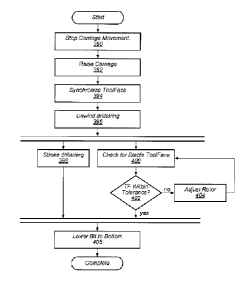
[0114] In an embodiment, individual subroutines in a PLC are incrementally
joined together
to enable full joints to be drilled autonomously with combinations of rotary
and slide drilling.
In certain embodiments, a bit is kept on bottom and low RPM drilling to
synchronize the BHA
toolface with surface position prior to slide drilling. This may allow a PLC
to stop the BHA
on toolface target and continue drilling in slide mode without needing to stop
drilling or lift
bit off bottom.
[0115] In some embodiments, a torque, drag, string windup, and hydraulic model
is run live.
The model may estimate the windup in the string and generate continuous
toolface estimation
to support autonomous control system while drilling at high Rate of
Penetration (ROP). In
18
CA 3013311 2018-08-03
WO 2011/130159 PCT/US2011/031920
certain embodiments, the model can generate output windup value at any time
and fill the
gaps between downhole updates. Hydraulic pressure may be calculated with
required
accuracy to get the motor torque. The weight on bit may also be obtained, for
example, for
mechanical specific energy ("MSE") analysis purposes.
.. [0116] In some embodiments, a friction factor may be determined from test
measurements.
For example, a friction factor may be established from motor output and torque
measured at
the surface. With input of drilling parameters such as RPM, ROP, surface
rotary torque,
surface hook load, the bit torque may be calculated. By matching the motor
torque value with
the calculated bit torque, an open hole friction factor can be determined (for
example, by
iterating to determine a value of a friction factor where the torques match).
In some
embodiments, weight on bit, torque along the string, and string windup are
obtained, for
example, by using the open hole friction factors measured automatically during
off ¨ bottom
motions of the drill string. In certain embodiments, if friction factor is at
or below a specified
minimum value (such as 0.2) or at or above a specified maximum value (such as
0.7), drilling
may be stopped and troubleshooting carried out.
[0117] Once the predicted down-hole WOB and the motor torque is available,
torque as a
function of the WOB may be computed, plotted, and displayed. In some certain
embodiments, an MSE curve is determined and displayed. Drilling may be
automatically
performed using the calculated values, such as the calculated WOB. In some
embodiments,
friction factor may be recalculated as drilling is carried out and used in
automatic drilling.
[0118] In one embodiment, a method of assessing a pressure used to form an
opening in a
subsurface formation includes measuring a baseline pressure when the drill bit
is freely
rotating in the opening in the formation. A baseline viscosity of fluid
flowing through the
drill bit is assessed based on the measured baseline pressure. As the drill
bit drills further into
.. the formation, the flow rate, density, and viscosity of fluid flowing
through the drill bit are
assessed. As drilling operations continue, the baseline pressure may
reassessed based on the
assessed flow rate, density, and viscosity of the fluid flowing through the
drill bit.
[0119] In some embodiments, viscosity may be determined from differential
pressure. In one
embodiment, Coriolis flow meters are used to measure flow and density into and
out of a well.
Differential pressure is measured across a defined length of mud delivery line
(which may be
between the pump and drill rig of a drilling system). FIG. 9 illustrates a
relationship between
differential pressure and viscosity in a pipe. The example illustrated in FIG.
9 is based on a
19
CA 3013311 2018-08-03
W02011/130159 PCT/US2011/031920
20m length of 2 inch mud delivery line. Curve 240 is based on a flow rate of
400 gallons per
minute. Curve 242 is based on a flow rate of 250 gallons per minute.
[0120] Determining viscosity using differential pressure may eliminate the
need for a
viscosity meter. In some embodiments, however, a viscosity meter may be
included in a
drilling system.
[0121] In one embodiment, a drill bit is automatically placed on a bottom of
the opening of a
subsurface formation. Mud pumps are started and after a predetermined time the
flow rate is
ramped (at a predetermined rate) to the target flow rate. Flow rate of fluid
into the drill string
is monitored and controlled to be the same (within user limit setpoints) as
the flow rate out of
the well. Standpipe pressure is allowed to reach a relatively steady state.
The drill string is
rotated at a predetermined RPM. The drill bit is moved toward the bottom of
the opening at a
selected rate of advance until a consistent increase in measured differential
pressure indicates
that the drill bit is at the bottom of the opening. In some embodiments, this
corresponds to bit
depth = hole depth (cavings in the bottom of the hole or errors in depth
measurement may,
however, cause the "bottom" to be detected despite mismatch in the depth
calculations). A
number of set points may be established and variables monitored during the
"lower bit to
bottom" routine. The drill string rotation may be performed prior to mud pumps
being
engaged to reduce pressure when recommencing mud flow in the annulus. The
drill bit may
be backed off the bottom of the opening if the flow rate of fluid into the
drill pipe is not
substantially the same as the flow rate of fluid out of the opening.
[0122] During drilling operations, once drilling has progressed to the maximum
available
depth for a given length of drill pipe, the drilling rig is used to finish
drilling and prepare to
add another length of drill pipe.
[0123] In n nibodimnt, a drilling pipe is advanced into a formation. The
advance of pipe
is stopped (for example, when the maximum available depth for the length of
drill pipe is
reached). Differential pressure across a mud motor is allowed to decrease. In
some
embodiments, differential pressure is allowed to decrease to a user set point.
Once the
differential pressure has decreased to a prescribed level, the drill string
may be picked up. A
torque and drag model may be used to monitor the forces needed to perform the
pickup. hi
one embodiment, the forces themselves can be predicted and used as alarm flags
(if exceeded,
for example, by a user defined amount). In another embodiment, the off bottom
friction factor
is used. For example, if the off bottom friction factor is over a specified
amount (such as >
CA 3013311 2018-08-03
WO 2011/130159 PCT/US2011/031920
0.5), a "tight hole pulling back" alarm condition may be triggered. Upon
triggering of an
alarm, a mitigation procedure may be commenced.
[0124] In an embodiment, the open hole friction factor is assessed during
drilling. In certain
embodiments, the open hole friction factor is continually assessed. For
example, in
embodiment, the open hole friction factor is continually assessed to verify
that "normal" well
bore conditions exist as a permissive for completion of the selected task(s).
Error handling
sub-routines may be defined to prevent and mitigate poor borehole conditions.
[0125] Mud motor stall is a common event. Typically, the power section of the
motor
contains a rotor that is driven to rotate by the flow of drilling fluid
through the unit. The speed
of rotation is controlled by fluid flow rate. The power section is a positive
displacement
system so as resistance to rotation (a braking torque) is applied on the rotor
(from the bit), the
pressure required to maintain the fixed fluid flow rate increases. Under
various conditions,
the capacity of the power section to keep the rotor rotating can be exceeded
and the bit stops
turning, i.e., a stall. A stall condition may sometimes occur within one
second.
[0126] FIG. 10 illustrates a method of detecting a stall in a mud motor and
recovering from
the stall according to one embodiment. At 260, a maximum differential pressure
is set for the
drilling operation. At 261, drilling may be commenced. At 262, differential
pressure may be
assessed. If the assessed differential pressure is at or above the assigned
maximum
differential pressure, a stall condition in the motor is assessed at 263.
[0127] Upon detection of a stall, flow to the mud motor is automatically shut
off (for
example, by turning off a pump for the motor) at 264. In some embodiments,
rotation of a
drill string coupled to the drill bit is automatically stopped at 265. In some
embodiments,
upon stall detection, drill pipe motion is automatically stopped (drill string
forward motion
reduced to zero). At 266, the differential pressure is allowed to drop below
the assigned
maximum differential pressure before allowing restart of the motor. In some
embodiments,
the excess pressure is bled off or allowed to bleed off. At 268, the drill bit
may be raised off
of the bottom of the well. At 270, the motor is restarted. At 272, drilling is
re-commenced.
[0128] In one embodiment, off bottom stand pipe pressure is measured during
drilling. A
mud motor maximum differential pressure is assessed. A stall is indicated when
the sum of
the off bottom stand pipe pressure and the motor maximum differential pressure
exceed a
specified level. In one embodiment, stand pipe pressure is measured with a rig
stand pipe
pressure sensor.
21
CA 3013311 2018-08-03
WO 2011/130159
PCT/US2011/031920
[0129] Excessive build up of cuttings in a well during drilling may adversely
affect a drilling
operation. In an embodiment, mass balance metering of drilled cuttings is used
to monitor
conditions of a well. In some embodiments, the information from the mass
balance metering
is used to automatically perform drilling operations.
[0130] In some embodiments, a method of assessing hole cleaning effectiveness
of drilling in
a subsurface formation includes determining a mass of rock excavated in a
well. The mass of
cuttings excavated from the well can be determined, in one embodiment, by
using an offset
log, real time logging while drilling ("LWD") log, of formation bulk density.
The length and
diameter of hole may be used to provide the volume, and the bulk density log
may provide the
density estimate.
[0131] k from the
well may be determined by measuring the total
mass of fluid entering the well and the total mass of fluid exiting the well,
and then
subtracting the total mass of fluid entering the well from total mass of fluid
exiting the well.
The mass of cuttings remaining in the well may be estimated by subtracting the
determined
mass of cuttings removed from the well from the determined mass of rock
excavated in the
well. In certain embodiments, a quantitative measure of hole cleaning
effectiveness may be
assessed based on the determined mass of cuttings remaining in the well. FIG.
11 illustrates
one embodiment of a method of determining hole cleaning effectiveness. Partial
fluid losses
may be taken into account by excluding the lost fluid mass from the
reconciliation.
[0132] In some embodiments, continuous monitoring of drilling fluids density
and flow rate is
achieved using Coriolis mass flow meters. In one embodiment, Coriolis meters
are provided
at both the suction and return line to physically measure the mass flow of
fluid entering and
exiting the well in real time. The Coriolis meters may provide flow rate,
density and
temperature data. In one embodiment, a densimeter, flow meter, and viscometer
are mounted
inline (for example, on a skid placed between the active mud tank and the mud
pumps). In
one embodiment, a viscometer is a Tr- 1 oo viscometer. The densimeter, flow
meter, and
viscometer may measure fluid going into the well. A second Coriolis meter is
installed at the
flow line to measure the fluid exiting the well.
[0133] In some embodiments, a control system is programmed to provide an
autonomous
drilling and data collection process. The process may include monitoring
various aspects of
drilling performance. One portion of the control system may be dedicated to
the processing of
drilling fluids data. The control system may use drilling fluids data manual
inputs, sensory
22
CA 3013311 2018-08-03
W02011/130159 PCT/US2011/031920
measurements, and/or mathematical calculations to help establish indicators
and trends to
validate drilling performance in real time. In some embodiments, the data
collected may be
used to determine a Hole Cleaning Effectiveness.
[0134] In some embodiments, drilling fluid parameters are measured in real
time. Real time
measurements may also increase objectivity of the data to facilitate an
immediate response to
drilling fluid fluctuations. In some embodiments, density, viscosity and flow
rate are
measured in real time while drilling. Real time control and data collection of
mudflow rate
and density in and out of the well may enable accurate drilling parameter
optimization. A
control system may, for example, automatically react and make optimization
adjustments
based on sensor signals (with or without human involvement).
[0135] In some embodiments, mass balance metering of drilled cuttings is used
to provide
trend indication for hole cleaning effectiveness. In one embodiment, a mass
balance
calculation for a Hole Cleaning Index (HCI) is determined by calculating the
volume of
cuttings left in the well and making an assumption that all the cuttings are
spread evenly along
the horizontal section of the well. The cuttings bed height can be calculated
and converted
into a cross sectional area occupied by cuttings.
HCI = Bit Open Area / Area Occupied by Cuttings
[0136] The wellbore column of fluid may be independent of the surface system.
Powder
products or liquid additives transferred into the active system (if there are
any such products
or additives) may not have any bearing on the mass balance of fluid being
circulated though
the well in real time. The excavated drilled cuttings may thus be the only
"additive" to the
column of fluid. An exception to the assumption that drilled cuttings are the
only additive
would be if there is an influx of water from the formation. In some
embodiments, water
influx is determined by monitoring for any unexpected decrease in rheological
properties
measured from an inline viscometer. In other embodiments, totalizing of the
volumes in
versus volume out can indicate fluid influxes. The HCI may be adjusted based
on any such
decrease to account for the water influx.
[0137] In one embodiment. a Coriolis meter has a preset calibration schedule.
The Coriolis
meter may have built-in hi/low level alarms to confirm that accurate data is
being received.
In one example, a 6" Coriolis meter has two flow tubes, each having a diameter
at 3.5" (88.9
mm). In one embodiment, the Coriolois meter controls the material flow to an
accuracy of
0.5 percent of the preset flow rate.
23
CA 3013311 2018-08-03
WO 2011/130159 PCT/US2011/031920
[0138] The use of automatic monitoring of cleaning effectiveness may eliminate
or reduce a
need for human monitoring of operations, such as monitoring of the shakers.
For example,
personnel may not be required at the shakers to measure viscosity and mud
weight a periodic
intervals. As another example, a mud engineer may not need to catch mud sample
at periodic
intervals.
[0139] Examples of mass balance monitoring are given below:
[0140] Example #1 - Start circulating
A suction meter and a flowline meter are read and assessed for balance.
(There may be a slight discrepancy due to fluid temperature, in that the
exiting
fluid will be wanner therefore possibly slightly lighter.)
Fluid In/Out: 2 m3/min x 1040 kg/m3= 2080 kg/min
Inline fluid viscometer may measure at 600, 300, 200, 100, 6 and 3-rpm
readings. The collection time may be 1 second at each rpm speed. 6 seconds to
process all six readings.
A temperature correction may be made based a "look-up" table.
[0141] Example #2 - Start drilling
A mass of rock generated may be based on rate of penetration and hole size.
The calculated mass of rock generated may be graphed in real time.
Hole Size @ 311 mm x ROP @ 100 m/hr = 7.59 m3 of cuttings excavated/hr
(7.59 m3/hr x 2600 kg/m3) / 60 min = 329 kg/min
2600 kg/m3 may be an assumed value for the density of cuttings -
alternatively, a density log "look-up" table from offset wells can be used to
characterize density for each formation
A look-up table may be provided that includes calliper log data from offset
wells to increase accuracy.
A look-up table may be provided that includes a washout percentage vs depth
from offset wells.
329 kg/min x 5% washout = 345 kg/min of rock being generated
A washout percentage may be graphed as a separate set of data points
The lag time may be computed based on the time it takes to empty the annulus
of mud calculated from the annular volume and flowrate (a "bottoms up" time)
24
CA 3013311 2018-08-03
WO 2011/130159 PCT/US2011/031920
Cuttings shape, size, fluid slip velocity, horizontal vs vertical drilling may
be
assessed
[0142] Example #3 ¨ Mass balance
The total mass of fluid going into the well and total mass of fluid exiting
the
well are metered. The total mass of fluid going into the well is subtracting
from the total mass of fluid exiting the well. The difference may indicate the
mass of drilled cuttings removed from the well.
Fluid In: 2.0 m3/min x 1040 kg/m3= 2080 kg/min
Fluid Out: 2.0 m3/min x 1180 kg/m3= 2360 kg/min
The difference is 280 kg/min
By subtracting this difference from the actual mass of rock excavated, an
indicator is obtained of a theoretical mass of drilled cuttings that has not
been
removed from the well.
Therefore 345 kg/min ¨ 280 kg/min = 65 kg/min left in the well
[0143] In an embodiment, flow measurements may be used to set permissives in
the control
system. For example, a permissive may be set based on whether the flow coming
out of the
well is equal to flow going into the well within an established tolerance.
[0144] In some embodiments, performance of a mud solids handling system is
monitored with
the Coriolis metering system. Density and rate (mass flow) of slurry from the
annulus of the
well may be metered coming into the solids control system. The efficiency of
the system in
removing solids may be measured by the Coriolis meter on the other side of the
system at the
point where the mud enters the mud pump to be sent back down the hole. By
tracking the
base density of the mud against the density of the mud going back down the
hole, the capacity
of the system to remove the drilled solids is assessed.
[0145] In some embodiments, solids left in the well are determined. An overall
solids control
system performance is determined based on an overall removal of rock mass from
both the
well and the drilling fluid. The overall solids control system performance may
provide an
indicator as to how much cuttings are left in the well. In one embodiment, the
measured mass
of rock is plotted against theoretical mass of rock generated. The result may
be displayed to
an operator in a graphical user interface. In certain embodiments, a Maximum
Solids
Threshold Limit is established. The limit may be automatically displayed to a
driller to
provide the driller with a visual cue that the well is not adequately being
cleaned. The limit
CA 3013311 2018-08-03
WO 2011/130159 PCT/US2011/031920
may be linked as a setpoint to be monitored by an automated drilling control
system. If the
system determines that wellbore cleaning is inadequate, mitigation subroutines
may be
initiated such as reducing rate of penetration, increasing flow rate,
increasing circulating time
and rotary speed in the rpe and post joint drilling phases.
[0146] One challenge encountered in directional drilling is controlling the
orientation of the
drill bit, or bottom hole assembly ("BHA") toolface. As used herein, "BHA
toolface" may
refer to a rotational position in which the direction deflecting device (such
as a bent sub) of a
drilling assembly is pointed. In a bottom hole assembly including a bent sub,
for example, the
BHA toolface is always oriented off-axis from the attitude of the drill string
at the end of the
string. Commonly, when a section is drilled in a rotary mode of drilling, the
BHA toolface
continually changes as the drill string rotates. The aggregate result of this
continually
changing toolface may be that the direction of the bottom drilling is
generally straight. In a
slide drilling mode, however, the orientation of the BHA toolface during the
slide will define
the direction of drilling (as the BHA toolface may remain pointed generally in
one direction
over the course of the slide), and therefore must be controlled within
acceptable tolerances.
In addition, when changing from one drilling segment to another segment or
from one drilling
mode to another drilling mode, reestablishing BHA toolface may require
substantial
involvement of an operator and/or may require that the drill bit be stopped,
both of which may
slow the rate of progress and efficiency of drilling.
.. [0147] The challenge of controlling BHA toolface may be compounded by drill
string
windup. During drilling, the drill bit and the drill string are subjected to
various torque loads.
In a typical rotary drilling operation, for example, a rotary drive, such as a
top drive or rotary
table, is operated to apply torque to the drill string at the surface of the
formation to rotate the
drill string. Since the bottom hole assembly and lower portions of the drill
string are in
contact with the sides and/or bottom of the formation, the formation may exert
counteracting,
resistive torque on the drill string in the opposite direction as the rotary
drive (e.g.,
counterclockwise, as viewed from above). These counteracting torques at the
top and bottom
of the drill string cause the drill string to twist, or "wind up", within the
formation. The
magnitude of the windup changes dynamically as the external loads imposed on
the drill
string change. In addition, the drill bit and the drill string may also
encounter torque related to
drilling operations (such as torque resisting rotation of the drill bit in the
opening). In drilling
systems where the angular orientation of the drill bit is used to control the
direction of drilling
26
CA 3013311 2018-08-03
WO 2011/130159 PCT/US2011/031920
(such as during slide drillin2), drill string wind up may limit an operator's
ability to control
and monitor the drilling process.
[0148] One way to measure toolface direction is with downhole instrumentation
(for example,
a MWD tool on a bottom hole assembly). As with any measurement from a MWD
tool,
however, the toolface measurements may not provide continuous measurement of
the
toolface, but only intermittent "snapshots" of the toolface. Moreover, these
intermittent
readings may take time to reach the surface. As such, when the drilling string
is rotating, the
most recently reported rotational position of the toolface from the MWD tool
may lag the
actual rotational position of the toolface.
[0149] In s , the rotational position of a drill string at the surface of a
formation is used to estimate the rotational position of the BHA toolface. In
one
embodiment, a rotational position of a BHA is correlated with a rotational
position of a top
drive rotating a spindle at the surface of a formation. For example, it may be
established that
under a particular condition, if the toolface is pointed up, then the
rotational position of the
top drive is at 25 degrees from a given reference. The process of correlating
the rotational
position of the BHA toolface with a rotational position at the surface of the
formation is
referred to herein as "synchronization". In some embodiments, synchronization
includes
dynamically computing a "Topside Toolface". The "Topside Toolface" at a given
time may
be the estimated rotational position of the toolface determined using the
measured actual
rotational position of the top drive, in combination with recent data on BHA
toolface received
from the MWD tool. Since the rotational position at the top drive is
continually available, the
Topside Toolface may be a continuous indicator of BHA toolface. This
continuous indicator
may fill the time gaps between the intermittent downhole updates from the MWD
tool, such
that better control of the toolface (and thus trajectory) is achieved than
could be done with
MWD toolface data alone. Once synchronized, the Topside Toolface may be used
by a
control system to stop the drill string with BHA toolface in a desired
rotational position, for
example, to conduct slide drilling.
[0150] In some embodiments, toolface synchronization is performed with the
drill string at a
specified RPM set point and a target motor differential pressure, while other
drilling set points
and targets are maintained.
[0151] In some embodiments, synchronization is based on BHA toolface data from
a MWD
tool. A gravity tool face ("GTF") value is received from the MWD tool.
Synchronization
27
CA 3013311 2018-08-03
WO 2011/130159 PCT/US2011/031920
may include synchronizing a BHA toolface with a rotary position at the surface
of the
formation. In certain embodiments, a Topside Toolface is used to predict where
the BHA
toolface value will fall when a value of the BHA toolface is received from the
MWD tool.
The lag time between downhole sampling of toolface and data decoding at
surface may be
accounted for by programming the lag time into a PLC or by measured and
accounting for an
RPM based offset (for example, by stopping the Topside Toolface early by the
"offset"
amount.) As noted above, once the toolface is synchronized, a programmable
logic controller
can stop the BHA toolface in a desired position to commence slide drilling.
[0152] FIG. 12 illustrates toolface synchronization using MWD data according
to one
embodiment. At 300, the surface rotor may be slowed to a toolface-hunting RPM.
At 302,
reading of BHA toolface may be read from a MWD tool until a designated number
of samples
has been reached.
[0153] At 304, high and lower rotor position limits may be determined around a
BHA
toolface setpoint. In one embodiment, the angle offset between the desired
toolface setpoint
is calculated from models and/or the stable average of the last toolface
readings. The Low
Desired Toolface Setpoint and High Desired Toolface Setpoint Limit may be
determined from
the desired MWD toolface. Topside Toolface (a rotational position) may be
calculated based
on current rotary position and the calculated angle offset.
[0154] At 306, an assessment is made whether the Topside Toolface is within
the established
tolerance. If the Topside Toolface is not within the established tolerance,
the rotor may
continue to turn at the hunting RPM. Topside Toolface may be reassessed until
the Topside
Toolface comes within the established tolerance. When the Topside Toolface is
within the
established tolerances, the drill string may be stopped by going to neutral at
308. In some
embodiments, a BHA toolface synchronization such as described above is used in
transition
from rotary drilling to slide drilling. In other embodiments, a BHA toolface
synchronization
may be used in a stop drilling routine. In certain embodiments, toolface
synchronization is
used when a drilling system is pulled back to the "stop" level to position the
MWD at the
same rotational position each time, which may minimize the roll dependent
azimuth
measurement variation.
[0155] In some embodiments, a drilling operation is carried out in two modes:
rotary drilling
and slide drilling. As discussed above, rotary drilling may follow a
relatively straight path
and slide drilling may follow a relatively curved path. The two modes may be
used in
28
CA 3013311 2018-08-03
=
W02011/130159 PCT/US2011/031920
combination to achieve a desired trajectory. In some embodiments, a drill bit
may be kept on
the bottom and rotating (at full speed or a reduced speed) during an
automatically controlled
transition from one drilling mode to another (such as from rotary to sliding,
or sliding to
rotary). In some embodiments, the bit may be kept on bottom and rotating (at
full speed or a
reduced speed) during an automatically controlled transition from one segment
to another
(such as from one slide segment to another slide segment). Continuing to drill
during
transitions may increase the efficiency and overall rate of progress of
drilling. In one
embodiment, a caniage drive (such as a rack and pinion drive) of a drilling
rig provides force
to maintain motor differential pressure at the target level. In other
embodiments, the weight of
the drilling tubulars within the well bore provides the force as the drilling
rig drawworks
allows the string to feed into the well bore.
[0156] In some embodiments, controlling a slide drilling operation includes
dynamic tuning
of the BHA toolface. In some embodiments, dynamic tuning is carried out during
transition
from a rotary drilling mode to a slide drilling mode. For example, to start a
transition to a
slide drilling mode, rotation of the drill string may be slowed to a stop. As
rotary drilling is
slowed to the stop, the BHA toolface may be synchronized. Once the BHA
toolface is
synchronized, the BHA toolface may be tuned (using, for example, holding
torque applied at
the surface of the drill string) to maintain the BHA toolface at a desired
rotational position
during slide drilling and using surface rotation to adjust the holding torque
up or down
intermittently to effect a change in the BHA toolface.
[0157] In some embodiments, a drilling system is prepared for slide drilling
by synchronizing
the BHA toolface and "topside toolface" to allow drill string rotation to be
stopped when the
BHA toolface is in the required position. Once the BHA toolface is stopped in
the required
position, unwinding the drill string may be performed to reduce the surface
torque to the
required holding torque. Once the drill string is unwound, the BHA toolface
may be
maintained with a holding torque imparted by a rotary drive system at the
surface of the
formation.
[0158] FIG. 13 illustrates a transition of a drilling system from rotary
drilling to slide drilling.
In this embodiment, the transition includes dynamic tuning of a BHA toolface,
At 318, the
BHA toolface is synchronized. In one embodiment, synchronization may be as
described
above relative to FIG. 12. In some embodiments, during or after
synchronization, the rotary
29
CA 3013311 2018-08-03
WO 2011/130159 PCT/US2011/031920
drive is stopped such that the BI-IA toolface is within tolerance of a desired
rotational position
setpoint.
[0159] In some embodiments, during toolface synchronization, differential
pressure across a
mud motor operating the drill bit (which may correlate to TOB and/or WOB) is
brought up to
and/or maintained at a target setpoint for slide drilling. In other
embodiments, differential
pressure may be at a level other than the target differential pressure for
slide drilling. In
certain embodiments, differential pressure across the mud motor is controlled
as a function of
BHA toolface. In one embodiment, if BHA toolface is within a range of a target
setpoint,
then differential pressure may be set to a slide drilling differential
pressure setpoint. In some
embodiments, differential pressure across the mud motor may begin at a reduced
set point
(such as 25 % of slide drilling target differential pressure) and then be
allowed to increase (for
example, in predetemined increments) based on offset from a BHA toolface
target.
[0160] At 320, the rotary drive may be stopped with the BHA toolface at the
desired setpoint.
At 322, the drill string may be unwound. Unwinding may be as fast as is
practical for the
drilling system. In some embodiments, unwinding may be based on a torque and
drag model
that includes string windup. In other embodiments, unwinding may be based on
surface
torque. In some embodiments, the string is unwound to a neutral holding
torque. In other
embodiments, the string may be unwound to a left roll holding torque. As used
herein, "left
roll holding torque" may be equal to bit torque as calculated form
differential pressure minus
a user-defined BHA "Left Roll Holding Torque" variable. A left roll holding
torque may be
suitable, for example, if a system tends to stop with BHA toolface rolled too
far to the right.
[0161] For the initial transition to slide drilling from rotary drilling, if
left roll holding torque
is being held, the BHA toolface roll may be monitored. If the BHA toolface is
rolling right
(forward), the BHA toolface will start rolling backwards as long as there is
negative torque at
the surface. The more negative torque, the faster BHA toolface should stop and
come
backwards. The BHA toolface may also be rotated backwards ("left") or forwards
("right")
with differential pressure changes.
[0162] If the BHA toolface is rolling left (backward), by contrast, the rotary
may be rotated
neutral holding torque (bit torque) as soon as the projected BHA toolface hits
tolerance.
[0163] The BHA toolface is unlikely to be stable initially. If the BHA
toolface is stable for a
long period, a failure alarm may be triggered.
CA 3013311 2018-08-03
WO 2011/130159 PCT/US2011/031920
[0164] At 324, the controller may monitor for stable BHA toolface. At 326, if
the BHA
toolface moves out of tolerance, the rotary drive at the surface may be
adjusted to bring the
BHA toolface back within tolerance.
[0165] In certain embodiments, a holding torque is about equal to the mud
motor output
torque as computed using a differential pressure relationship. The surface
holding torque is
increased / decreased by surface rotation to maintain the equivalent torque as
output by the
mud motor, unless toolface changes down hole are required. In one example, an
increase in
motor output torque of 200 ftlb may require a forward rotation at the surface
of 45 degrees
before a surface torque increase of 200ftlb is measured. The topside toolface
may remain the
.. same during the adjustment of holding torque.
[0166] In an embodiment, a control system automatically reduces the target
differential
pressure during a transition from rotary drilling to slide drilling. Once
slide drilling is
established, the control system may automatically resume the original target
differential
pressure.
[0167] Monitoring of BHA toolface may be based on measurements from downhole
instrumentation, surface instrumentation, or a combination thereof. In one
embodiment,
monitoring of BHA toolface is based on a downhole MWD tool. In one embodiment,
delta
MWD toolface ("DTF") rate is monitored. If the BHA toolface moves out of the
tolerance
window, a surface rotor may be adjusted at 328. For a given rate of
penetration, the DTF
may be fairly constant for a given right roll holding torque. As the BHA rolls
in response to
left roll holding torque, the surface torque will go down. Surface torque may
be maintained
with rotation to hold left roll holding torque and the DTF rate. The left roll
holding torque is
dynamic (based on bit torque), so if the motor torque increases due to
formation change, left
roll holding torque target in the PLC may require surface clockwise rotation
(this surface
clockwise rotation would counter a tendency for the BHA toolface to roll
left.) As soon as the
BHA toolface rolls into the tolerance window (based on projecting the last
measured DTF
forward in time), surface torque may be returned to neutral holding torque
(which may be the
same as bit torque as calculated from differential pressure) by rotating the
rotary drive at the
surface.
[0168] At 330, slide drilling may be performed. The controller may monitor for
stable BHA
toolface, and the rotary drive may be adjusted to maintain the BHA toolface in
a desired
31
CA 3013311 2018-08-03
WO 2011/130159 PCT/US2011/031920
rotational position. As discussed above, in some embodiments, drilling may
continue
throughout the transition from a rotary drilling mode to a slide drilling
mode.
[0169] In some embodiments, once the BHA toolface has settled into the window
(based on
DTF) with surface torque equal to neutral holding torque, the string can
optionally be
automatically wiggled, wobbled or rocked to mitigate drag. Tweaking of BHA
toolface can
be done by rotating the required increment at the surface, holding position
and allowing the
torque at surface to return naturally to the holding torque.
[0170] Table 1 is an example of user setpoints for tuning.
:$045Wil:t.-71rT77.7"%F.111.10816.6,
Toolface sync RPM 5
Initial slide drilling DiffP % of maximum 60
DiffP resume rate 1 minute
Toolface tolerance + 10
Toolface tolerance ¨ 10
LRT 1 500 ftlb
LRT 2 750 ftlb
LRT 3 1000 ftlb
RRT 1 500ftlb
RRT 2 750ft1b
RRT 3 1000ftlb
Toolface sync stop rotary TTF offset -30 deg
[0171] In one embodiment, to adjust the rotor to return the BHA toolface to
the setpoint, the
rotor may be turned until the current rotor Topside Toolface (TTF) is within
tolerance of the
Desired Toolface. As used in this example, Topside Toolface refers to the down
hole MWD
toolface transpose to the topside rotary position. The Topside Toolface may
make use of the
last good MWD toolface reading and the current rotary position. For example,
if the drill
string is wound up and the last toolface was 30 degrees from the Modeling
setpoint, the
topside rotary position may be rotated 30 degrees in the direction that the
drill string is wound
up.
[0172] In some embodiments, a tuning method includes slowing a rate of
progress, reducing
the drill string RPM at the surface to zero, unwinding to a user defined
"unwind torque"
(which corresponds to a negative holding torque), and pausing between surface
adjustments
32
CA 3013311 2018-08-03
WO 2011/130159 PCT/US2011/031920
based on projected BHA toolface that takes DTF into account versus time. As
the projected
BHA toolface comes into the required range, the suiface rotary position may be
adjusted to
resume neutral holding torque. As shown in FIG. 4, the greater the negative or
positive
holding torque (in that case indicated by torque at drive sub), the greater
the rate of change in
DTF (see the rate of change in BHA right roll). In certain embodiments, the
relationship
between the magnitude of the negative / positive holding torque and the rate
of change in DTF
is mapped automatically.
[0173] In some embodiments, a tuning method includes making two more
adjustments to a
surface rotor to achieve a desired BHA toolface. Between each adjustment, the
rotor may be
paused until the BHA toolface stabilizes. FIG. 14 is a plot over time
illustrating tuning in a
transition from rotary drilling to slide drilling with surface adjustments at
intervals. Curve
340 represents a toolface target. Points 342 represent readings from a gravity
toolface (for
example, from an MWD tool). Curve 344 is a curve fit of points 342. Curve 346
represents
the rotational position of an encoder on a rotary drive. Curve 348 represents
a Topside
Toolface. Curve 350 represents surface torque. Curve 352 represents zero
torque.
[0174] Initially at 354, the drilling system is operated in a rotary mode. At
point 356,
toolface synchronization is commenced at 5 rpm. At 358, a reverse rotate
adjustment is
made. At 360, a forward rotate adjustment is made. At 362, the BHA is stable
and surface
torque may equal bit torque. At 364 and 366, forward rotate adjustments are
made. At 368
the BHA is again stable and surface torque may be equal to bit torque. At 370,
the drilling
system may re-enter a rotary drilling mode.
[0175] In some embodiments, a carriage or other drill string lifting system
may be controlled
(for example, raised and lowered during a transition from rotary drilling to
slide drilling.
FIG. 15 illustrates a transition from rotary drilling to slide drilling
including carriage
movement according to one embodiment. At 390, carriage movement of a drilling
system is
stopped. At 392, the carriage may be raised (for example, to bring the drill
bit of the system
off-bottom). In one embodiment, the carriage is raised about 1 meter.
[0176] At 394, the BHA toolface is synchronized. In one embodiment,
synchronization may
be as described above relative to FIG. 12. The rotary drive may be stopped
with the BHA
toolface at the desired setpoint. At 396, the drill string may be unwound.
Unwinding may
be as described above relative to FIG. 13.
33
CA 3013311 2018-08-03
WO 2011/130159 PCT/US2011/031920
[0177] At 398, the drill string may be stroked while checking for a stable BHA
toolface. A
stroke may include raising and then lowering the carriage by an equal amount
(such as two
meters up and two meters down). The controller may monitor for stable BHA
toolface at
400. At 402, if the BHA toolface moves out of tolerance, the surface rotor may
be adjusted
at 404 to bring the BHA toolface back within tolerance.
[0178] At 406, the drilling bit may be lowered to the bottom of the formation.
In some
embodiments. the BHA toolface may be lowered to bottom a predefined angle to
the right of
the target BHA toolface. This may allow the BHA toolface to walk to the left
as bit torque
increases during drilling. In some embodiments, monitoring and tuning as
described at 402
and 404 may be continued as slide drilling is carried out.
[0179] In some embodiments, a method of controlling drilling directions
includes
automatically rotating a drill string at multiple speeds during a rotation
cycle. In certain
embodiments, drilling at multiple speeds in a rotation cycle may be used in a
course correct
procedure. For example, drilling at multiple speeds in a rotation cycle may be
used to nudge
the path of the hole back into line with a straight section of the well. In
one embodiment,
automatically rotating a drill string at multiple speeds is used as a course
correct following a
straight ahead lateral.
[0180] FIG. 16 illustrates an embodiment of drilling in which the speed of
rotation of the drill
string is varied during the rotation cycle. At 410, a target trajectory is
established. At 412,
during drilling operations, a drill string is rotated at one speed during one
portion of the
rotation cycle. At 414, the drill string is rotated at a second, slower speed
during another,
"target" portion of the rotation cycle. Slower rotation in the target portion
of the rotation
cycle may bias the direction of drilling in the direction of the target
portion.
[0181] In some embodiments, the sweep angle of the target portion of the
rotation cycle is
equal to the sweep angle of the other portion of the rotation cycle (i.e., 180
degrees in each
portion). In other embodiments, the sweep angle of the target portion of the
rotation cycle is
unequal to the sweep angle of the other portion of the rotation cycle. In one
example, the
slower, target speed is 1/5 of the initial speed for the rotation cycle.
However, various other
speed ratios and angular proportions may be used in other embodiments. For
example, a
target speed may be 1/ 6, 1/ 4, 1/ 3, or some other fraction of the initial
speed. In certain
embodiments, the speed of a rotor may vary continuously over at least a
portion of a rotation
34
CA 3013311 2018-08-03
WO 2011/130159 PCT/US2011/031920
cycle. In certain embodiments, a rotor may rotate at three or more speeds
during a rotation
cycle.
[0182] FIG. 17 illustrates a diagram of a multiple speed rotation cycle
according to one
embodiment. In the example shown, the rotor speed is 5 RPM for 270 degrees of
the rotation
cycle, and 1 RPM for the remaining 90 degrees of the rotation cycle.
[0183] In some embodiments, a desired turn rate is achieved based on rotor
speeds and sweep
angles. In one example, a turn rate is estimated as follows:
[0184] Assumptions:
[0185] At a target range is 90 degrees (+/-45degrees of intended angle change
direction), a net
half the build rate may be expected in the average target range direction. If
the motor pulls
10deg/30m with full slide, the net would be 5deg/30m.
[0186] RPM is 5 and 1, 270 deg at 5rpm (30deg/sec), then 90deg at 1 rpm
(6deg/sec).
[0187] In the target range, the BHA dwells for 15 seconds while on the
opposite side, the
BHA takes 3 seconds to traverse the opposite target range. The discount on 5
deg/30m is
thus 3/15 x 5 = ldeg/30m. Any meters drilled in one orientation may be
counteracted by
meters drilled in the opposite orientation.
[0188] Based on the preceding calculations, 4deg/30m would be the expected
build rate. This
build rate is further reduced, however, because there are two toolface
quadrants to be
traversed outside the target and backside that also do not contribute to net
angle change. In
particular, for 6 second per revolution or 6 seconds per 24 seconds the BHA is
in the left or
right from target quadrant so 6/24 x 4deg/30m = 1. This yields an expected
build rate of
3deg/30m using a 10deg/30m sliding BHA, which translates, for example, to 0.2
deg angle
change if the procedure was employed for 2m out of a 9.6m joint.
[0189] Minimum curvature is commonly used in is calculating trajectories in
directional
drilling. Minimum curvature is a computational model that fits a 3-dimensional
circular arc
between two survey points. Minimum curvature may, however, be a poor option if
the sample
interval used to take surveys does not capture the tangent points along the
varying curvature.
Ideally, surveys would be taken each time the drilling was changed from rotary
drilling to
slide drilling or each time that the toolface orientation of the BHA was
changed. Such
.. repeated surveying would be time consuming and costly.
[0190] In an embodiment, attitudes (azimuth and inclination) at the known
points along a
wellpath may be used, in combination with the rotary drilling angle change
tendency, to
CA 3013311 2018-08-03
WO 2011/130159 PCT/US2011/031920
estimate the attitudes at the start and end points of the slide drilled
section without the need
for extensive surveys. The rotary drilling angle change tendency is determined
by observing
the change in drilling angle as measured during a preceding section of rotary
drilling. The
estimated attitudes can be used as "virtual" measured depths to better
represent the actual path
of the borehole and therefore improve position calculation.
[0191] In one embodiment, a method of predicting a direction of drilling of a
drill bit used to
form an opening in a subsurface formation includes assessing a depth of the
drill bit at one or
more selected points along the wellbore. An estimate is then made, based on
the assessed
depths, of the attitudes at the start and end points of each slide drilled
section. For slide
drilled sections contained within the measured surveys, virtual measured
depths, with attitude
estimates, are assessed by projecting from a current survey back to one or
more previous
measured depths. These virtual measured depths, in some embodiments, may be
used to
evaluate the slide drilling dogleg severity ("DLS") and toolface performance
(for example,
where the trajectory of the well actually went compared to where the BHA was
pointed). The
rotary drilling dogleg severity and toolface performance may also be evaluated
based on
sampling sections of hole drilled entirely in rotary mode that contain at
least two surveys.
[0192] In some embodiments, a projection to bit is refreshed based on drilling
mode and
sampled DLS tendencies each time a measured depth is updated. In certain
embodiments, a
projection back to the previous measured depth is made to install virtual
measured depths,
with attitude estimates, for slide drilled sections contained within measured
depth boundaries.
[0193] In some embodiments, the path of a borehole made using a combination of
rotary
drilling and slide drilling is estimated using a combination of actual survey
data (such as from
downhole MWD tools) and at least one drilling angle change tendency
established during
rotary drilling. For example, if a borehole is formed by rotary drilling,
slide drilling, and
rotary drilling in succession, an angle change tendency while rotary drilling
is initially
determined (for example, using survey data). A directional change value (such
as a dog leg
angle) is determined for the slide drilled section based on actual surveys
(for example, using
actual surveys that flank the slide drilled section). The directional change
value of the slide
drilled section may be adjusted based on the flanking surveys. The adjusted
directional
change value may account, for example, for any portion between the actual
surveys that was
rotary drilled and for the angle change tendency during such rotary drilling.
A net angle
change across the slide drilled section may be determined using previously
determined project
36
CA 3013311 2018-08-03
WO 2011/130159 PCT/US2011/031920
ahead data (which may include, for example, the attitudes at the start and
ends of the slide). A
projection to bit value may be refreshed using the net angle change. The
refreshed projection
may be used to estimate the path of the borehole, for example, as part of a
"virtual"
continuous survey.
[0194] FIG. 18 illustrates a schematic of a drill string in a borehole for
which a virtual
continuous survey may be assessed. In FIG. 18, drill string 450 includes drill
pipe 452. Drill
string 450 has been advanced into a formation. Portion 454 has been advanced
using rotary
drilling, portion 456 has been advanced by slide drilling, and portion 458 has
been advanced
by rotary drilling. Stations 460 (marked by asterisks) are the survey
("measured") depths.
The survey depths correspond to the position of the MWD sensor behind the bit.
For this
example, distance between the bit and MWD sensor is around 14 meters so, for
example, as
the bit is drilled to 20m, the MWD sensor just arriving at 6m. As the bit is
drilled to 30m
(assume 10m drill pipe lengths) the MWD sensor just arrives at 16m. The first
three joints are
rotated to 30m. At this time, there are 30m of rotated hole and 2 full sample
intervals of
rotary drilling. Surveys at 6m and 16m, along with previously taken surveys,
are all taken in
the hole that has been rotary drilled. The rotary drilling angle change
tendency can be
determined by analyzing the drift (e.g., attitude) in the position of the MWD
sensor for at least
three surveys. In one embodiment, the first and last survey are used to
determine the change
in attitude during rotary drilling, this change in attitude can be used to
determine the rotary
drilling angle change tendency. For purposes of this example, the rotary
drilling angle change
tendency during drilling was determined to be 0.5deg/30m @ 290deg.
[0195] For this example, the last 3m of joint 4 is slide drilled. This takes
the hole depth from
37m to 40m. The next two joints are rotary drill to take the hole depth to
60m. At this point
the bit is at 60m, the MWD sensor is at 46m, and a slide drilled section is
contained within the
depth interval of 36 ¨ 46m.
[0196] The dogleg angle ("DL") and toolface ("TF') for the slide drilled
section may be
calculated using the actual surveys that straddle the slide drilled section.
In the context of the
surveys described relative to FIGS. 18-18C, "toolface" refers to the effective
change in the
direction of a hole. For purposes of the surveys described in FIGS. 18-18C,
"TFO setting
offset", or "Toolface Offset Offset" refers to the difference between the
direction the motor
(for example, the bend on a bent sub motor) was pointed and where the hole
actually went.
For purposes of this example, the values for the actual survey are as shown
below:
37
CA 3013311 2018-08-03
W02011/130159
PCT/US2011/031920
Meas. Depth Inclination Azimuth Dogleg DLS Toolface
36 90 45
46 94 47 4.47 13.41 26.49
[0197] The dogleg angle due to rotary drilling angle change tendency, over 7m
at 0.5deg/30m
@ 290 can be determined as 7/30*0.5 = 0.12 deg @ 290
[0198] 0.12 at 290 degrees can be considered as representing a polar
coordinate.
[0199] This value may be converted to rectangular coordinates
Dogleg Toolface X Y Dx Dy
4.47 26.49 1.9938 4.0007
0.12 290 -0.113 0.041 2.107 3.960
[0200] Dx and Dy may be converted back to polar coordinates:
[0201] Based on the foregoing calculations, the slide drilled section had an
angle change of a
dogleg angle of 4.49deg at toolface of 28.01.
[0202] From the original project ahead data, a net angle change across the
slide drilled section
may be determined, for example, by taking the Start slide drilling inclination
and azimuth and
the Start rotation drilling again inclination and azimuth and then using these
values to
calculate a net dogleg angle and toolface.
[0203] The projection may be refreshed. Assuming that the projection estimate
was that the
slide drilling DL was 0.5 @ 045deg, a refreshed projection based on 30/3 x
4.49 = 44.9
deg/30m. The Toolface offset offset is about 45 ¨ 28 = 17 deg.
[0204] The recalculated projection may now approximate the attitude at 46m as
the
measurement from the MWD.
[0205] In certain embodiments, goal seeking may be performed to make
projection DL the
same as the actual (measured) DL by changing an original sliding DLS
prediction. In certain
embodiments, goal seeking may be performed to make Projection Toolface Offset
("TFO")
the same as the actual (measured) TFO by changing TFO setting offset. In some
embodiments, "virtual surveys" are inserted into the survey file. In one
embodiment, the
virtual survey may be used to assess performance for a slide drilling BHA.
Example
[0206] Non-limiting examples are set forth below.
[0207] FIG. 18A depicts a diagram illustrating an example of slide drilling
between MWD
surveys. In the example illustrated in FIG. 18A, a 4m slide is carried out
from a survey depth
38
CA 3013311 2018-08-03
WO 2011/130159 PCT/US2011/031920
of 1955.79 to 1959.79, at a toolface setting of 130. The net angle change
between the
1955.67m survey and the 1974.5m survey was determined to be 0.75 degrees and
the direction
of the angle change was determined to be 90.00438 degrees relative to hiside
(at 1955.67m).
For this example, in the original projection ahead, the dog leg severity for
the slide drilling
section was 12 degrees/30m and the TFO setting offset was -10 degrees. The dog
leg severity
for rotary drilling was 0.6 degrees/30m at a toolface setting of 290.
[0208] Based on the foregoing information, the dogleg caused by the slide
drilled section and
effective toolface offset of the angle change that occurred in the slide
drilled section were
determined as follows: Goal seeking was carried out to make projection dogleg
equal to
actual (MWD) dogleg by changing the original sliding dog leg severity
prediction. Based on
the dogleg goal seek, the dogleg severity for the slide was reduced to 7.83
degrees/30m.
Goal seeking was then carried out to make Projection Toolface Offset equal to
actual (MWD)
toolface offset by changing the Toolface Setting Offset. Based on this TFO
goal seek, the
dogleg severity was further reduced to 7.7517 degrees/30m and the TFO setting
offset was
changed to -34.361511 degrees. New points representing the start and end of
the slide
section were then determined to produce two virtual surveys.
[0209] FIG. 18B is tabulation of the original survey points for this example.
FIG. 18C is
tabulation of the survey points for this example with the two new virtual
survey points added
in rows 460. In addition, in FIG. 18C, the trajectory estimate for the end
survey position at
1974.5m has been updated in cells 462 (compared to the values in corresponding
cells 464 for
the original end survey position at 1974.5m shown in FIG. 18B.)
[0210] In certain embodiments, an updated Toolface offset offset and new
estimate for sliding
dogleg severity are used for real time project to bit and steering
calculations.
[0211] Vertical appraisal wells can provide some top elevation data concerning
a formation.
Unfortunately, horizontal well MWD survey elevation data may have a higher
uncertainty
than the thickness of the oil production well "sweet spot" (for example, a 4m-
thick sweet spot
with a +/-5m MWD survey). In addition, from structure contours built up from
horizontal
well MWD data, significant variance may be encountered.
[0212] In some embodiments, a true vertical depth ("TVD") is assessed using
measurement of
fluid density. In one embodiment, a method of assessing a vertical depth of a
drill bit used to
form an opening in a subsurface formation includes measuring downhole pressure
exerted by
a column of fluid in a drill pipe. The density of the column of fluid is
assessed based on a
39
CA 3013311 2018-08-03
WO 2011/130159 PCT/US2011/031920
density measurement at the surface of the formation (for example, with a
coriolis meter on the
suction side of a mud pump). A true vertical depth of the drill bit may be
determined based
on the assessed downhole pressure and the assessed density. The true vertical
depth is used
to control subsequent drilling operations to form the opening. In some cases,
a control
system automatically adjusts for variations in mud density within the system.
[0213] In some cases, TVD measurement data is used to control jet drilling.
[0214] In one embodiment, a method for determining true vertical depth
includes installing a
coriolis meter as a slipstream on the outlet of the mud tank. A pressure gauge
of optimum
range and accuracy may be coupled to an MWD tool. A pressure transducer is
installed in the
MWD tool. A density column is modeled in a PLC to account for mud density
variation in
the time taken to fill the build section. Internal BHA pressure is sampled.
The internal
pressure may transmitted to the surface and/or stored. In one embodiment, the
pressure
signature of "pumps off' is detected (see, for example, FIG. 19) and the
static fluid column
pressure is measured and reported to the surface PLC such as at 502.
[0215] In one embodiment, the pressure exerted by a column of fluid inside a
drillpipe is
recorded using a pressure sensor (attached, for example, to the end of the MWD
apparatus
inside a first nonmagnetic collar). The density of the column of fluid may be
measured with a
Coriolis meter on the suction side of a mud pump. Real time, full steam
density may be
measured on the suction line of the pumps using, for example, a +/- 0.5kg/m3
accuracy
Coriolis meter. The data sets may be used to calculate TVD. In one embodiment,
internal
pressure at the BHA is recorded using, for example, a +/- 0.5 psi pressure
transducer.
[0216] FIG. 19 illustrates an example of pressure recording during "pumps off'
adding of a
joint of drill pipe according to one embodiment. In the example shown in FIG.
18, the flat-
line pressure was extracted along with mud density data to calculate the
vertical height of the
fluid column. Curve 500 is a plot of pressure recorded during connection. The
flat section at
502 represents a full and stationary string of fluid with the top drive
disconnected waiting for
the next joint to be added.
[0217] FIG. 20 illustrates an example of density TVD results. Set of points
504 and set of
points 506 each correspond to a different lateral. Lines 508 and 510 (positive
and negative
TVD, respectively) correspond to a curve fit of the data. Lines 512 and 514
(positive and
negative TVD, respectively) correspond to a 2 sigma ISCWSA standard survey.
The density
TVD data obtained in this example may resemble magnetic ranging position
calculations.
CA 3013311 2018-08-03
WO 2011/130159 PCT/US2011/031920
Each value is unique and not subject to the cumulative error that might be
obtained using
systematic MWD inclination measurement error. The longer the horizontal, the
greater may
be the advantage of TVD based on density over MWD TVD assessment. For example,
as
reflected in FIG. 20, the cloud of data for TVD based on density may have only
about half the
spread of the 2 sigma ISCWSA MWD standard survey model.
[0218] A best fit using this data set suggests the actual location of the well
path is equivalent
to a 0.15 deg systematic inclination measurement error below the calculated
position.
[0219] In some embodiments, a compensation may be made, in a density TVD
calculation,
for one or more of the following sources of error: (1) contaminated pressure
measurements
from imperfections/deficiencies in float sub use / design; (2) malfunctioning
mud pump
charge pumping system and cavitation bubbles causing density measurement
noise; and (3)
mud density variation not taken into account in the build section.In one
embodiment, the
density TVD measurement is used to verify position in hole for handling down
hole tools or at
critical depths such as tangents in the wellpath.
[0220] MWD tools often include sensors that rely on magnetic effects. The
large amount of
steel in a bottom hole assembly may cause significant error in MWD survey
data. One way of
reducing this error is to space the MWD tool a significant distance (such as
16 meters) away
from the major steel components of the BHA. Such a large spacing between the
BHA and the
MWD sensors may, however, make directional steering much more difficult,
especially in
horizontal drilling. In some embodiments, a calibration procedure is used to
measure and
account for the interference on Bz of a bottom hole assembly. In one
embodiment, a method
of measuring and accounting for magnetic interference from a BHA includes: (1)
measuring
the pole strength of the steel BHA components; (2) recording MWD grid
correction /
declination / Btotal & Bdip measurement locally with a site roll-test with
tool on a known
alignment, (3) calculating the Bz interference at the chosen nonmagnetic
spacing; (4) using
the planned wellpath geometry to plan spacing requirements, (5) applying an
offset (during
drilling or post drilling) allowing for the known interference to MWD Bz
measurements; and
(6) recalculating the azimuth using modified Bz measurement. In some
embodiments, BHA
components may be degaussed.
[0221] In some embodiments, inertial navigation sensors such as fibre optic
gyros may be
used for drilling navigation. Optical gyro sensors may, in some cases, replace
magnetic
sensors, thereby alleviating the interference effects of steel in a BHA.
41
CA 3013311 2018-08-03
=
WO 2011/130159 PCT/US2011/031920
[0222] A method of steering a drill bit to form an opening in a subsurface
formation includes
using real-time project to bit data. The real-time data may be, for example,
data gathered
between periodic updates ("snapshots") from a measurement while drilling (MWD)
tool on a
bottom hole assembly. In one method, a survey is taken with the MWD tool. The
survey data
from the MWD tool establishes a definitive path of the MWD sensor. The
attitude measured
at the sensor is used as a starting point from which to project the attitude
and position of the
drill bit in real-time. The real-time projection to bit may take into account
drilling parameters
as toolface values recorded against sliding intervals. When a subsequent
survey is taken with
the MWD tool to produce a new definitive position and attitude, the real-time
project to bit is
updated based on the new definitive path and the values used for toolface
offset offset and
sliding dogleg severity are updated for subsequent projections to bit.
[0223] In some embodiments, trajectory calculation is based on surveys (such
as quiet surveys
collected while adding drillpipe to the string). The survey data may be
collected by direct link
to the MWD interface hardware / software. The data may be attached to the
Measured Depth
as generated by bit depth value - Bit lead value. The trajectory calculation
may be treated as
a "definitive" path for the purpose of drilling a hole.
[0224] In some embodiments, the system automatically accumulates a database.
In the
database, the intervals drilled with rotation and the intervals drilled
sliding may be recorded.
The intervals drilled sliding may be updated each time toolface data point is
received from the
MWD. The toolface value is recorded against that sliding interval.
[0225] As drilling of the next joint is prepared, the definitive path updates
to as close as it
ever gets to the bit (hole depth - bit lead).
[0226] As a definitive path updates prior to commencing a new joint of
drilling, the project to
bit calculation may update as follows:
(1) If the section ahead of the bit is all rotation, the attitude at the bit
is estimated
accordingly.
(2) If there is slide drilling in the section ahead of the sensor, the
attitude may be
estimated by accumulating dl (differential length) at the received toolfaces
over the
recorded intervals.
(3) Attitude change may be accumulated to the current bit position taking into
account
all toolface v. interval steps and rotary drilling sections.
42
CA 3013311 2018-08-03
WO 2011/130159
PCT/US2011/031920
[0227] The real time project attitude to bit may be used for a real time bit
position calculation
(which may be tied onto the last definitive path position point).
[0228] FIG. 21 is a plot of true vertical depth against measured depth
illustrating one example
of a project to bit. Point 550 is a previous definitive inclination point.
Point 552 is a
projected inclination point. Point 554 is an "about to receive" definitive
inclination point.
Point 556 is a new projected true vertical depth (TVD) point. For a 15m bit
lead, the project
to bit starts at 15m distance as the system begins to drill a new joint. The
project to bit
extends out to 15m + joint length just before the next quiet survey is
received. In one
embodiment, a non-rotating sensor housing may be used. Difference 558
represents an error
projection. In some embodiments, the error projection is tracked for
inclination and azimuth
for the attitude at the bit (for example, position up/down, left/right).
[0229] A method of steering a drill bit to form an opening in a subsurface
formation using an
optimum align method includes taking a survey with a MWD tool. The survey is
used to
calculate the hole position. A project to bit is determined (for example,
using best-fit curves).
The project to bit is used in combination with an optimum align method to
maintain the drill
bit within a predetermined tolerance of a drilling plan.
[0230] In one embodiment, implementation of steering in a PLC includes taking
a survey and
adding the survey to a calculated hole position. A project to bit is performed
(using for
example, best fit curves for build up rate ("BUR") or toolface results, or a
rotary vector).
Formation corrections (such as elevation triggers/gamma triggers) and drilling
corrections
(toolface errors, differential pressures out of set range) may be applied. In
certain
embodiments, learned knowledge may be accounted for (for example, a running
average of
BUR) when correcting best fit curves. A bit projection may be added to the
survey. A
project ahead may be determined.
[0231] Slide records may be maintained in a database manually or
automatically. As the
driller performs slide and rotate intervals, the system may automatically
generate slide
records. These records may also be entered and edited by a user. Slide records
may be
recorded with Time, Depth, Slide (Yes/No), Toolface and DLS. Slide records
have two main
functions: (1) to project from the last survey to the end of the hole (the
project may be a real
time calculated position of the end of hole; and (2) to analyze the sliding
performance.
[0232] In certain embodiments, a system includes a motor interface. The motor
interface may
be used after tests have been performed (for example, a pressure vs. flow rate
test) and an
43
CA 3013311 2018-08-03
8165655
adequate number of samples have been captured. From the tests, trend lines
(such as pressure vs.
flow rate) may be generated.
[0233] In an embodiment, a method of generating steering commands includes
calculating a
distance from design and an angle (attitude) offset from design. The angle
offset from design may
represent the difference between what the inclination and azimuth of the hole
actually is compared
to the plan. The angle offset from design may be an indication of how fast the
hole is diverging /
converging relative to the plan. In some embodiments, distance from design and
an angle
(attitude) offset from design are calculated in real time based on the
position of the hole at the last
survey, the position at the projected current location of the bit, and the
projected position of the bit
1 0 (e.g., a project ahead position).
[0234] In certain embodiments, a tuning interface allows a user to adjust the
steering instructions,
for example, by defining setpoints in a graphical user interface. In certain
embodiments, tuning
controls may be used to establish a "look-ahead" distance for computing
steering instructions.
[0235] FIG. 22 is a diagram illustrating one embodiment of a plan for a hole
and a portion of the
hole that has been drilled based on the plan. Plan 570 is a curve representing
the path of a hole as
designed. Plan 570 may be a line from start to finish of a well that defines
the intended path of the
well. Hole 572 is a curve representing a hole that has been partially drilled
based on plan 570.
MWD survey points 574 represent points at which actual surveys are taken as
hole 572 is drilled.
The actual surveys may be taken using MWD instruments such as described
herein. MWD
surveys at each of MWD survey points 574 may provide, for example, a position
(defined, for
example, by true vertical depth, northing, and easting components) and
attitude (defined, for
example, by inclination and azimuth). As previously discussed, MWD
instrumentation may be up
hole (such as about 14 meters) from bit 576.
[0236] Point 576 represents a projected position (current bit position as
projected from MWD
survey) of the end of a drill bit being used to drill the hole. Line 577
represents an attitude of the
bit at point 576.
[0237] In certain embodiments, from the last MWD survey, the angle of a hole
is calculated to the
current bit position based on a slide table. If the hole is rotary drilled to
the current bit location
from the last MWD survey, the projection may use the rate of angle change
(dogleg severity) in a
particular toolface direction that is selected for rotary drilling. In some
embodiments, a controller
uses the automatic BHA performance analysis values for rotary drilling dogleg
severity and
direction. In other embodiments, a controller uses manually entered values.
Once the rate and
44
CA 3013311 2018-08-03
81656552
direction of the curve that the BHA will follow is defined, the system may
track the bit depth in
real time and perform vector additions of the angle change to maintain a real
time estimate of
inclination and azimuth at the bit.
[0238] A similar method may be used for slide drilling, with, in some cases,
an additional user
setup step of defining where the sliding toolface will be taken from. For
example, the sliding
toolface may be taken from real time updates from the MWD, or from a toolface
setting defined
prior to drilling the joint (for example, a controller may calculate that a 5m
slide with toolface set
at 50 degrees is required).
[0239] In certain embodiments, a topside toolface setting may be used to
determine the projected
bit position. A topside toolface might be used, for example, for a system
having a slow MWD
toolface refresh rate.
[0240] FIG. 23 illustrates one embodiment of a method of generating steering
commands. A
method of generating steering commands may be used, for example, in making a
hole such as the
hole shown in FIG. 22. At 580, a current survey at a bit for an actual hole
being drilled is
determined. The survey may include a position and attitude of the bit. In some
embodiments, a
current survey may be used to project a future position of a bit in real-time,
for example, from
actual MWD survey data. For example, with reference to FIG. 22, a current
position for bit 576
may be projected from a MWD survey taken at most recent MWD survey point 574A.
[0241] At 582, a distance from the determined position of the bit to planned
(designed) position of
the bit is determined. In some embodiments, a three dimensional "closest
approach" distance of
the bit from the plan is calculated. (A closest approach plan point is shown,
for example, at point
590 shown in FIG. 22 and arrow 597 illustrates the closest 3-D distance.) From
the three
dimensional closest approach distance calculation, the depth of the planned
pathway ("depth on
plan") that corresponds to the three dimensional point is determined. Using
the depth on plan
value, the planned position and attitude values, such as plan inclination,
azimuth, easting,
northing, and TVD at the determined depth on plan point may be calculated (by
interpolation, for
example). The calculated position and attitude values may be used to calculate
the changes in the
toolface to return the hole back to the planned position.
[0242] A direction from the current bit location back to the planned bit
position may be
calculated. For example, the toolface from the plan point to bit (determined
from the
three-dimensional closest approach) may be determined. The reverse direction,
the toolface from
bit back to plan, may also be determined.
CA 3013311 2018-08-03
81656552
[0243] At 584, an attitude of the plan (azimuth and inclination) is determined
at a specified
lookahead distance 599. (A lookahead point on a plan and corresponding
attitude are shown, for
example, at point 592 and attitude 594 shown in FIG. 22.) In some embodiments,
the inclination
and azimuth are interpolated at the lookahead distance. The specified distance
may be, for
example, a user-defined distance. In one embodiment, the lookahead distance is
10m. The project
ahead for the lookahead may be determined in a similar manner as used to
project the survey at a
projected bit position.
[0244] At 586, a tuning convergence angle is determined based on distance from
bit to plan. The
tuning convergence angle may be, in certain embodiments, the angle that the
toolface is altered to
bring the bit back to the planned position. In some embodiments, the tuning
convergence angle
varies based on bit three-dimensional separation from plan.
[0245] In certain embodiments, a convergence angle may be determined on a
sliding scale. The
table below gives one example of a sliding scale for determining a tuning
convergence angle.
3D Separation Tuning convergence Notes
(m) angle (degrees)
>0.5 0 May reduce the steering
to
allow convergence
>0.50m <lm 1 Steer for convergence
>lm < 2m 2 Stronger steer tendency
>2 3 May require relatively
severe
correction
[0246] At 588, a target attitude (azimuth and inclination) is determined. The
target attitude may be
based, for example, on the attitude of the plan at the lookahead distance. In
some embodiments,
the target attitude is adjusted to account for a tuning convergence angle,
such as the tuning
convergence angle determined at 586.
[0247] At 590, one or more steering instructions are determined based on the
target attitude
relative to current bit attitude determined at 588. In some embodiments, a
steering solution
matches an angle as determined at the lookahead distance, plus an additional
convergence angle
required at that lookahead position. (A direction for a steering instruction
is represented, for
example, at arrow 596 shown in FIG. 22.)
46
CA 3013311 2018-08-03
WO 2011/130159 PCT/US2011/031920
[0248] In some embodiments, once a target angle has been defined at the
lookahead distance,
the toolface required to get there and the length of slide drilling needed are
calculated (for
example, at the defined dogleg severity for the sliding motor performance). In
one
embodiment, a dogleg and TFO required are calculated between a current survey
at bit and a
.. target inclination/azimuth. Using input sliding dog leg severity
expectation, a slide length to
achieve the required dogleg may be calculated. The toolface may be calculated
as, for
example, a gravity toolface or a magnetic toolface. In certain embodiments, a
controller
automatically uses a magnetic toolface when bit attitude has an inclination
less than 5 degrees.
In some embodiments, dogleg severity / toolface response values are fixed, for
example, by a
user. In certain embodiments, BHA performance analysis automatically generates
a steering
solution required to respond to the output.
[0249] In some embodiments, a PLC incorporates a sliding scale of steering
control response
through setpoint tuning parameters. The further (distance) the hole is away
from design, the
larger the convergence angle may be used to calculate as a course correction.
FIG. 24
illustrates one embodiment of a user input screen for entering tuning set
points. The tuning
angle of convergence may be used as the angle of convergence back to plan. For
example,
when the hole is close to plan, the PLC may put "zero convergence" into the
lookahead to
generally maintain a parallel trajectory. As the hole gets further away, the
system may
increase the convergence angle depending on how far away the hole gets from
the plan. For
example, when 0 - 0.5m away from plan, the system may look at the angle of the
plan 10m
further on from current bit position and use that inclination and azimuth,
plus 0 degree
convergence angle, to determine if a steer is required. If 0 - 3m away from
plan, the system
may look at the angle of the plan 10m further on from current bit position and
use that
inclination and azimuth, plus a 1 degree tuning convergence angle, to
determine if a steer is
required.
[0250] In certain embodiments, additional tuning criteria of minimum and
maximum slide
distance may be established a command to be passed through to the PLC. For
example, based
on the setpoints shown in FIG. 24, only slides greater than lm or less than 9m
slides may be
allowed.
[0251] In some embodiments, while drilling, surveys are captured and
projections are made to
the end of the hole. The control system may calculate the point at which a
slide should be
47
CA 3013311 2018-08-03
WO 2011/130159
PCT/US2011/031920
performed. Set points may direct the calculations to tell the system when to
slide and for how
long.
[0252] Inputs may include one or more of the following:
- 3D Max Displacement from Plan ¨ Defines the maximum displacement from plan
that the well bore is allowed to go before the controller provides a
correcting slide.
- Min. Slide Distance ¨ Restricts the minimum slide length, ignoring required
slides
that are less than this value.
- Max. Slide Distance ¨ Restricts the maximum slide length.
- Average Joint Length ¨ Estimate of the average joint length.
- TFO Drift Tolerance ¨ Allow the slide drilling to continue with the current
TF when
the live MWD TF drifts from the desired TF.
- BHA Performance Lookback ¨ Distance up the hole to analyze the BHA
peiformance.
- BHA Slide Performance Analysis - Option to calculate the slide performance
in real
time
- BHA Rotate Performance Analysis - Option to calculate the rotate performance
in
real time
- TF Seeking Lead Distance ¨ Issues the command to go into slide mode early
by
specified depth.
[0253] In some embodiments, the information describing the cuffent borehole
location and
the directional drilling requirements to get back to a plan are provided in
the control system in
the form of drilling directives. The directives are automatically calculated
as each joint is
completed. The user has the option to leave the calculated results or modify
them. Under
ideal conditions, the user will simply leave this screen alone. And each
subsequent joint will
automatically update as the drilled joint is completed.
[0254] Drilling directives may be used to instruct the drilling sequence to be
performed for
the next joint. The directives may be automatically calculated as each joint
is completed.
Each subsequent joint may automatically update as the drilled joint is
completed.
[0255] In some embodiments, tuning of steering decisions may be accomplished
by radial
tuning. Radial tuning may include, for example, keeping within a given
distance from design
which is the same in any up/down ¨ left/right direction. In other embodiments,
tuning may be
used to implement "rectangular" steering decisions. In one example of
rectangular steering,
48
CA 3013311 2 0 1 8-0 8-0 3
W02011/130159 PCT/US2011/031920
the lateral position specification for the bit path is allowed to be greater
than the vertical
position. For example, the bit may be allowed to be 10 m right of design but
kept vertically
within 2 m offset from design.
[0256] In some embodiments, a set of limiting setpoints are established based
on geosteering.
The geosteering-based setpoints may work in a similar manner to drilling
setpoints, except
they operate to affect a planned trajectory. For example the planned path may
remain valid
unless gamma counts (or other geosteering indicator signal) exceed a user
setpoint then
planned inclination is reduced by an angular user setpoint until new planned
trajectory is user
setpoint-defined amount below previous planned trajectory.
[0257] A method of estimating toolface orientation between downhole updates
during drilling
in a subsurface formation includes encoding a drill string (such as with an
encoder on a top
drive) to provide angular orientation of the drill string at the surface of
subsurface formation.
The drill string in the formation is run in calibration to model drill string
windup in the
formation. During drilling operations, values of angular orientation of the
drill string are read
.. using the encoder. Toolface orientation may be estimated from the angular
orientation of the
drill string at the surface, with the drill string windup model accounting for
windup between
the toolface and the drill string at the surface. The toolface estimation
based on surface
measurement may fill the gaps between telemetric updates from measurement
while drilling
(MWD) tools on the bottom hole assembly (which are "snapshots" that may be
more than 10
seconds apart).
[0258] In some embodiments, a string windup model is created based on a
calibration test. In
one embodiment, the drill string may be rotated in one direction until the BHA
is rotating and
a friction factor has stabilized, at which time the windup is measured. The
drill string is then
rotated in the opposite direction until the BHA is rotating and a friction
factor has stabilized,
at which time the windup is again measured. Based on the results of the
calibration test, a live
estimate of BHA toolface is used to fill in the gaps between downhole
measurements
readings.
[0259] As discussed previously, in some embodiments, a friction factor may be
determined
from test measurements. For example, a friction factor may be established from
motor output
and torque measured at the surface. A string windup may be determined
analytically by
calculating a torque for each element and cumulative torque below that element
using the
49
CA 3013311 2018-08-03
WO 2011/130159 PCT/US2011/031920
friction factor determined from test measurements. From the calculated
torques, the twist
turns for each element and total twist turns on surface may be determined.
[0260] In some embodiments, a surface rotary position is synchronized with
downhole
position to allow estimates of downhole toolface to be made based on windup
variation
caused by torque changes measured during drilling between toolface updates.
[0261] In certain embodiments, a system includes a graphical display of
winding in a drill
string. For example, a graphical display may show movement of wraps/rotation
traveling up
and down the string as torque turns change form either end of the drill
string.
[0262] Further modifications and alternative embodiments of various aspects of
the invention
may be apparent to those skilled in the art in view of this description.
Accordingly, this
description is to be construed as illustrative only and is for the purpose of
teaching those
skilled in the art the general manner of carrying out the invention. It is to
be understood that
the forms of the invention shown and described herein are to be taken as the
presently
preferred embodiments. Elements and materials may be substituted for those
illustrated and
described herein, parts and processes may be reversed, and certain features of
the invention
may be utilized independently, all as would be apparent to one skilled in the
art after having
the benefit of this description of the invention. Changes may be made in the
elements
described herein without departing from the spirit and scope of the invention
as described in
the following claims. In addition, it is to be understood that features
described herein
independently may, in certain embodiments, be combined.
CA 3013311 2018-08-03