Note: Descriptions are shown in the official language in which they were submitted.
CA 03013373 2018-08-01
WO 2017/144091 PCT/EP2016/053841
PROCESSING APPARATUS AND METHOD FOR DETECTING PARTIAL
DISCHARGE PULSES IN THE PRESENCE OF NOISE SIGNALS
BACKGROUND
[001] Technical field
[002] The present invention relates to a processing apparatus and method
for
recognising partial discharges in electrical components and systems, such as:
medium or high voltage cables, cable joints, overhead line insulators, medium
and
high voltage switchboard boxes, high and extra-high voltage cables using GIS
(Gas
Insulated Switchgear) and other electrical apparatus where partial discharges
can
be observed.
[003] Description of the Related Art
[004]
The term "partial discharges" (PD) is intended to indicate an undesired
recombination of electric charges occurring in the dielectric (insulating)
material of
electric components, in the presence of defects of various types, eventually
leading
to dielectric destruction. Here, a pulse current is generated in portions of
dielectric
material and causes an electromagnetic impulsive signal to propagate through
the
power or ground cables of the relevant electric system, and radiating through
the
various surrounding media (dielectric material, metals, air, etc.).
[005]
According to the state of the art, PD measurement is carried out by
employing a sensor connected or positioned near the component under test to
detect pulse signals. The pulse signals collected by the sensor are acquired
by an
electronic device that usually comprises a high speed digital data acquisition
stage
and data storage module, communication and post-processing (analyzing)
devices.
[006] A
difficulty in performing PD measures is to reliably discriminate between
real PD pulses and external noise that is often composed by pulses very
similar to
the PD. According to one method, in Alternate Current (AC) systems, the
detected
pulses are correlated with the phase of the voltage powering the component
under
1
CA 03013373 2018-08-01
WO 2017/144091 PCT/EP2016/053841
test: since real PDs originate mainly at specific phase intervals, it is
possible to
highlight them (noise instead tends to be equally scattered at every phase
angles).
This known technique, called "Phase Resolved PD Pattern" implies to measure
and
acquire the voltage phase angle (by using a dedicated sensor) along with the
PD
signal. The Phase Resolved PD Pattern method cannot be used in Direct Current
(DC) systems where the voltage is constant and not sinusoidal, so there is not
a
phase reference to be detected.
[007]
Other methods employed to discriminate PD from noise are based on the
analysis of the pulse waveforms, by means of feature extraction and clustering
algorithms. These methods imply the acquisition of a large number or pulses
(many
of which are noise) with a very high sampling rate, so requiring complex and
expensive hardware.
[008] Document
W02013/185820 describes a partial discharge acquisition and
analysis device structured to detect a synchronization signal representing the
supply voltage phase angle and perform extraction of features of the pulses
acquired by a sensor. The pulse features extracted according to this prior art
documents are: peak value and polarity, phase, energy, duration and rough
estimation of Weibull parameters.
[009]
Document EP2411823 discloses a method for locating partial discharges
occurring at a discharge site in an electric apparatus with elongate geometry.
The
partial discharges are corresponding electric pulses propagating in opposite
directions along the apparatus from the discharge site. Moreover, the method
comprises: selecting, for the pair of correlated subsets, at least one pair of
homologous pulses detected in different sensors in the same time interval; and
calculating the distance between the discharge site and the sensors.
[0010] Document
JPH01184474 refers to a technique for locating the position
where partial discharge occurs without being affected by an external noise.
The
method is based on detecting an electric field pulse generated by the partial
discharge of the cable to be measured by electric field optical sensors which
are
arranged at specific positions and locating the position of the partial
discharge
2
CA 03013373 2018-08-01
WO 2017/144091 PCT/EP2016/053841
according to the level and arrival time difference of the signal propagating
along an
optical fibre connected with the optical sensors. Using a plurality of sensors
placed
along a cable the partial discharge occurrence position is found from the
arrival
time difference between one electric field optical sensor and another electric
field
optical sensor.
[0011] Brief Summary Of the Invention
[0012]
The Applicant observes that the known partial discharge acquisition
methods implement complex techniques to discriminate partial discharge pulses
from external noise and, particularly, some of the prior art methods
employable for
discriminating noise in AC electrical systems cannot be used in DC electrical
systems.
[0013] The
Applicant found that the discrimination of partial discharge pulses
generated inside a monitored electrical object from noise generated outside
the
monitored electrical object can be based on the measure of a time interval
comprised between detection events occurred at two detectors placed at
different
areas of the electrical object.
[0014]
According to a first aspect, the present invention relates to a processing
apparatus for detecting partial discharge pulse in the presence of noise
signal
comprising:
a first detector configured to detect an electromagnetic impulsive signal
from a first area of an electrical object and generate a first electrical
pulse
associated with a first detection event of the electromagnetic impulsive
signal;
a second detector configured to detect the electromagnetic impulsive signal
from a second area of the electrical object and generate a second electrical
pulse
associated with a second detection event of the electromagnetic impulsive
signal;
a time calculation module configured to measure a time interval comprised
between the first detection event and the second detection event;
a processing module connected to the time calculation module configured
to:
compare the measured time interval with a time threshold
3
CA 03013373 2018-08-01
WO 2017/144091 PCT/EP2016/053841
value;
associate the electromagnetic impulsive signal to partial
discharge pulses generated inside the electrical object between the
first and second areas, if the measured time interval is lower than the
time threshold value; and
associate the electromagnetic impulsive signal to a noise
signal generated outside the electrical object, if the measured time
interval is equal to or greater than said time threshold value.
[0015] With the term "area" it is meant a zone or a point on the electrical
object or
close to the electrical object from which electromagnetic signals propagating
inside
the electrical object can be detected from outside.
[0016] According to an embodiment, the processing apparatus further
comprises
a first conversion device configured to receive the first electrical pulse and
generate a first time signal at a first detection time;
a second conversion device configured to receive the second electrical pulse
and generate a second time signal at a second detection time;
and the time calculation module is configured to measure the time interval
comprised between the first and second detection times.
[0017] Preferably, said first conversion device includes a first
voltage comparator
structured to compare the first electrical pulse with a voltage threshold, and
generate the first time signal assuming:
- a first logical level if the voltage of the first electrical pulse is
greater than the
voltage threshold, and
- a second logical level if the voltage of the first electrical pulse is equal
to or lower
than the voltage threshold.
[0018] Preferably, the second conversion device includes a second voltage
comparator structured to compare the second electrical pulse with the voltage
threshold, and generate the second time signal assuming:
- the first logical level if the voltage of the second electrical pulse is
greater
than the voltage threshold, and
- the second logical level if the voltage of the second electrical pulse is
4
CA 03013373 2018-08-01
WO 2017/144091 PCT/EP2016/053841
equal to or lower than the voltage threshold.
[0019]
Particularly, said first and second voltage comparators are fast comparators.
[0020]
Preferably, each of said first and second detectors includes one of the
following sensor devices: High Frequency Current Transformer, capacitive
coupler, antenna sensor, electromagnetic sensor. Particularly, each of said
first and
second detectors is an active electromagnetic sensor having a frequency
response
from 5MHz to 20MHz.
[0021] Advantageously, the processing module is configured to count a
number of
a plurality of electromagnetic impulsive signals having a corresponding
measured
time interval lower than the time threshold value and compare said number with
a
reference value.
[0022] Preferably, the time calculation module comprises a Time-to-
Digital-
Converter circuit and is configured to generate said time interval under the
form of
a digital value. Particularly, the Time-to-Digital-Converter circuit is
configured to:
start computing of the time interval when the first time signal is received by
the
Time-to-Digital-Converter circuit;
stop computing of the time interval when the second time signal is received
by the Time-to-Digital-Converter circuit.
[0023]
According to an embodiment, the Time-to-Digital-Converter circuit
comprises a first input port for receiving said first time signal and a second
input
port for receiving said second time signal. Advantageously, the Time-to-
Digital-
Converter circuit shows a time resolution comprised between 0.01 ns and 10 ns.
[0024]
The processing apparatus further comprises a storage module connected to
the processing module and configured to store a detection digital value
representing
that partial discharge pulses have been detected when the measured time
interval is
lower than the threshold value.
[0025]
According to a second aspect the present invention relates to a processing
method for detecting a partial discharge pulse in the presence of noise
signal, the
5
CA 03013373 2018-08-01
WO 2017/144091 PCT/EP2016/053841
method comprising the steps of:
- providing an electrical object to be monitored,
- detecting an electromagnetic impulsive signal from a first area of the
electrical object and generating a corresponding first electrical pulse
representing a
first detection event of the electromagnetic impulsive signal;
- detecting the electromagnetic impulsive signal from a second area of the
electrical object and generating a second electrical pulse representing a
second
detection event of the electromagnetic impulsive signal;
- measuring a time interval comprised between the first detection event and
the second detection event;
- comparing the measured time interval with a threshold value;
- associating the electromagnetic impulsive signal to partial discharge
pulses generated in the electrical object between the first and second areas
if the
measured time interval is lower than the threshold value; and
- associating the electromagnetic impulsive signal to a noise signal if the
measured time interval is equal to or greater than the threshold value.
[0026] Advantageously, the partial discharge processing method
further comprises:
- converting the first electrical pulse into a first time signal
representing a first
detection time;
- converting the second electrical pulse into a second time signal
representing
a second detection time;
and wherein the step of measuring the time interval comprises:
evaluating an interval comprised between the first and second detection
times.
[0027] Preferably, the electrical object to be monitored comprises a
Direct Current
operating electrical object.
[0028] BRIEF DESCRIPTION OF THE DRAWINGS
[0029] Further characteristics and advantages will be more apparent
from the
following description of preferred embodiments given by way of example, with
reference to the enclosed drawings in which:
6
CA 03013373 2018-08-01
WO 2017/144091 PCT/EP2016/053841
[0030]
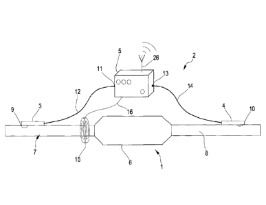
FIG. 1 shows an embodiment of a partial discharge detection apparatus
employable to monitor an electrical object;
[0031]
FIG. 2 shows an example of a signal processing module employable by said
partial discharge detection apparatus;
[0032] FIG. 3 and
FIG. 4 refer to examples of a method for discriminating external
noise from partial discharges implementable with said partial discharge
detection
apparatus;
[0033]
FIG. 5 schematically shows a flowchart of a particular partial discharge
detection and alarm generation method;
[0034] FIG. 6
shows several possible levels among which a voltage threshold can
be selected;
[0035]
FIG. 7 shows as an example the distribution of detected pulses among
different pulse typologies.
[0036] DETAILED DESCRIPTION
[0037]
Figure 1 shows an electrical object 1 and a partial discharge detection
apparatus 2 comprising a first detector 3, a second detector 4 and a signal
processing module 5. The electrical object 1 can be a component, device,
apparatus
or system which can produce partial discharge electromagnetic pulses and is,
as an
example: a medium or high voltage cable, a cable joint, an overhead line
insulator,
a medium or high voltage switchboard box, a high and extra-high voltage cable
using GIS (Gas Insulated Switchgear), an electric motor, an electric generator
or a
medium or high voltage transformer or the like. The electrical object 1 can be
either an AC or a DC electrical object. In accordance with the particular
example
shown in FIG. 1 the electrical object 1 is a cable joint 6 which joins a first
cable 7
with a second cable 8. The first and second cables 7, 8 can be, as an example,
HVAC (High Voltage Alternate Current) cables.
[0038] The partial
discharge detection apparatus 2 is structured to monitor the
status of the cable joint 6 by detecting partial discharge pulses and
discriminating
them from electrical pulses due to external noise. The external noise can be
any
signal, either due or not due to partial discharge phenomena, generated in the
environment external to the electrical object 1 or generated inside the
electrical
7
CA 03013373 2018-08-01
WO 2017/144091 PCT/EP2016/053841
object 1 but outside a measuring section including the monitored cable joint
6.
[0039]
The first detector 3 and the second detector 4 are configured to detect
electromagnetic pulses and generate corresponding electric signals to be
provided
to the signal processing module 5. Each one of the first detector 3 and the
second
detector 4 can be or can include a corresponding sensor configured to convert
electromagnetic pulses into electrical pulses. The first and second detectors
3 and 4
can be passive sensors or, preferably, active sensors, e.g. sensors provided
with an
active local electronic amplifier.
[0040]
Particularly, the first detector 3 and/or the second detector 4 can be one of
the following sensor devices: High Frequency Current Transformer, capacitive
coupler, antenna sensor, electromagnetic sensor. The first detector 3 and the
second
detector 4 shown in FIG. 1 are, as an example, active electromagnetic sensors.
[0041]
As an example, the first detector 3 and the second detector 4 show a
respective bandwidth B comprised between 1 MHz and 100 MHz. Preferably, the
bandwidth B is comprised between 5 MHz and 25 MHz. In accordance with a
particular embodiment, the first detector 3 and the second detector 4 can be
implemented by an electrical field sensor as described in the patent
application
PCT/EP2014/060141. This electrical field sensor comprises a first conductive
electrode and a second conductive electrode (not shown). The electrodes are
made,
by way of example, by respective conductive sheets, such as metal sheets
having,
as an example, a thickness lower than 0.05 mm, preferably comprised between
0.01
mm and 0.05 mm. According to an example, both first and second electrodes of
the
electrical field sensor have flat rectangular or quadrangular shapes.
[0042]
As shown in FIG. 1 the first detector 3 and the second detector 4 are placed
in such a way to detect electromagnetic impulsive signals from distinct areas
of the
electrical object 1. Particularly, the first detector 3 is placed in contact
or in
proximity to a first area 9 of a section of the first cable 7 entering the
cable joint 6
and the second detector 4 is placed in contact or in proximity to a second
area 10 of
a section of the second cable 8 exiting the cable joint 6: with this
arrangement the
cable joint 6 is comprised between the first area 9 and the second area 10 and
the
8
CA 03013373 2018-08-01
WO 2017/144091 PCT/EP2016/053841
first detector 3 and the second detector 4 are near to the cable joint 6. In
this
example, the first area 9 and the second area 10 correspond to ports of the
electrical
component to be monitored, i.e. an input port and an output port of the cable
joint
6.
[0043]
As an example, if the electrical object 1 is a cable termination, the first
area
9 can be an input port where the cable enters the termination and the second
area
can be a ground connection or a bus bar. In accordance with another
embodiment, if the electrical object 1 is three-phase machine (a transformer,
a
10 motor or generator) one of the three-phase inputs (or outputs) and
the ground
connection can be used as first area 9 and second area 10. Also Gas Insulated
Switchgears show several ports to be used as first and second areas 9 an d 10
to
arrange the first detector 3 and the second detector 4. It is noticed that in
some
cases more than two detectors can be used. As an example, in order to monitor
three-phase machines one detector per phase can be employed in order to
monitor
each phase separately..
[0044]
The first detector 3 is connected to a first input 11 of the signal processing
module 5 by a first signal cable 12 and the second detector 4 is connected to
a
second input 13 of the signal processing module 5 by a second signal cable 14.
Preferably, the first signal cable 12 and the second signal cable 14 are of
the same
length which is comprised in the range 1 m-50 m, particularly 1 m-10 m, but in
special cases the signal cables can be long up to lkm (e.g. for monitoring
submarine cable segments and joints).
[0045]
The signal processing module 5 is structured to receive electric signals from
the first detector 3 and the second detector 4 and processing them in order to
associate the detected signals to partial discharge pulses generated inside
the cable
joint 6 between the first and second areas 9 and 10 or to a noise signal
generated
outside first and second areas 9 and 10.
[0046]
The partial discharge detection apparatus 2 can include a power supply
module configured to provide electrical power to the signal processing module
5.
The power supply module can include a battery, a power adaptor connected to a
9
CA 03013373 2018-08-01
WO 2017/144091 PCT/EP2016/053841
low voltage Grid or preferably a magnetic energy harvester 15, as shown in
FIG. 1.
The magnetic energy harvester 15 is a magnetic coil (operating as a current
transformer) that extracts electrical energy from the first cable 7 and
transmits it to
the signal processing module 5 via a supply cable 16. In accordance with an
embodiment, the magnetic energy harvester 15 and the signal processing module
5
can be integrated together to form a single device to be permanently installed
or
even integrated on the electrical object 1: as an example, this solution is
preferable
for monitoring of HV and MV cable joints.
[0047] In
accordance with a preferred embodiment the magnetic energy harvester
is a current transformer and comprises a toroid of ferromagnetic material
clamped on the first cable 7 or on the second cable 8. The toroid has about
100
coils and is able to generate a voltage from 3V to 20V when a current of about
50A
to 1000A flows in the electrical object 1. The generated voltage is rectified
and
15
regulated by specific power supply circuit (not shown). As an example, the
power
consumption of the signal processing module 5 is less than 100mW average, the
greatest part being for the communication interface (that has peaks of 2W when
active).
[0048] FIG. 2
shows a particular embodiment of the signal processing module 5
comprising a time calculation module 17 and a control and processing module
18.
The time calculation module 17 is configured to measure, from electrical
pulses
detected by the first and second detectors 3 and 4, at respective first and
second
detection events, a time interval TD comprised between the first and second
detection events. The control and processing module 18 is configured to
compare
the measured time interval TD with at least one time threshold value THt to
associate the detected electrical pulses to partial discharge pulses or to
noise.
Possible levels among which the time threshold value THt is set are disclosed
in
detail in the following description with reference to the example shown in
figure 6.
[0049]
Particularly, the time calculation module 17 is provided with a third input
19 connected to the first signal cable 12 and a fourth input 20 connected to
the
second signal cable 14. The time calculation module 17 includes a Time-to-
Digital
Converter (TDC) circuit, which is structured to measure the time interval
CA 03013373 2018-08-01
WO 2017/144091 PCT/EP2016/053841
comprised between an arrival time of an electrical signal received at the
third input
19 (or the fourth input 20) and another arrival time of another electrical
signal
received at the fourth input 20 (or third input 19). As an example, the TDC
circuit
17 is configured to measure the time interval by performing a time counting
triggered by an initial signal received at one of its inputs and stopped by
the
subsequent received signal. The time calculation module 17 can be implemented
by
a commercially available TDC integrated circuit or in a FPGA (Field
Programmable Gate Array). The TDC circuit 17 is configured to provide on an
first
output 21 an output signal representing the measured time interval TD under
the
form of a digital value.
[0050]
Preferably, the employed TDC circuit 17 shows a resolution comprised
between 0.01 ns and 10 ns, more preferably the resolution is comprised between
0.01 ns and 1 ns; still more preferably the resolution is in the range 0.01 ns
¨ 0.5
ns. In accordance with an example, the TDC circuit 17 shows a maximum counting
interval of 5gs with no dead-time and a counting resolution of about 16 bit.
For
specific applications, where a maximum range lower than 10Ons is expected
(e.g.
for very short electrical components to be monitored), a counting resolution
also
lower than 8 bit may be employed.
[0051]
The control and processing module 18 is configured to receive the signal
representing the measured time interval TD and compare it with the time
threshold
THE to determine if partial discharges or noise have been detected. The time
threshold THE corresponds to a propagation time employed by an electrical
pulse
generated at the first area 9 and propagating along the cable joint 6 to reach
the
second area 10 (or vice versa). The value of the time threshold THE can be
evaluated theoretically or can be measured experimentally by employing the
first
and the second detectors 3 and 4.
[0052] According
to the results of the comparing step, the control and processing
module 18 is configured to associate a detected electromagnetic impulsive
signal to
partial discharge pulses generated inside the cable joint 6, between the first
and
second areas 9 and 10, if the measured time interval TD is lower than the time
threshold THE. On the contrary, if the measured time interval TD is
equal/greater
11
CA 03013373 2018-08-01
WO 2017/144091 PCT/EP2016/053841
to/than said time threshold THE, the control and processing module 18
associates
the detected electromagnetic impulsive signal to a noise signal generated
outside
the cable joint 6.
[0053] Moreover,
the control and processing module 18 is configured to generate
control signals ScNT to be transmitted to the time calculation module 17. As
an
example, the control signals SCNT may include interrogation signals with which
the
control and processing module 18 triggers a time measure to be performed by
the
time calculation module 17. As an example, the control and processing module
18
is configured to require measured data from the time calculation module 17 at
the
end of measure windows of 10 s. The control and processing module 18 can
include a Control and Processing Unit (CPU) and is provided with a memory
module (not shown) to store digital values representing the results of the
comparing
step with the time threshold THE. As an example, the control and processing
module 18 is implemented by means of a microcontroller.
[0054]
In accordance with the example shown in FIG. 2 the signal processing
module 5 further comprises a first conversion module 22 and a second
conversion
module 23. The first conversion module 22 is structured to generate from a
first
electrical pulse Pi provided by the first detector 3 a first time signal Sit
to be sent to
the time calculation module 17 to indicate that a first detection event is
occurred in
the first detector 3. The second conversion module 23 is structured to
generate
from a second electric pulse P2 provided by the second detector 4 a second
time
signal Sa to be sent to the time calculation module 17 to indicate that a
second
detection event is occurred in the second detector 4.
[0055]
Particularly, the first conversion module 22 includes a first voltage
comparator Cvi and the second conversion module 23 includes a second voltage
comparator CV2 to perform comparing with a voltage threshold THY. In
accordance
with a particular embodiment, the first conversion module 22 further comprises
a
first voltage amplifier Al structured to amplify the first electrical pulse Pi
and
provide a first amplified electrical pulse PAi to the first voltage comparator
Cvi.
The first voltage comparator Cvi is configured to compare the first amplified
electrical pulse PAi with the voltage threshold THv and provide the first time
signal
12
CA 03013373 2018-08-01
WO 2017/144091 PCT/EP2016/053841
Si representing a first logical level (e.g. the bit 1) if the voltage of the
first
amplified electrical pulse PAi is greater than the voltage threshold THv, or a
second
logical level (i.e. the bit 0) if the voltage of the first amplified
electrical pulse PAi is
equal/lower to/than the voltage threshold THY. The first voltage comparator
Cvi
and the second voltage comparator Cv2 can be realized, preferably, by
corresponding fast comparators. Typically, a fast comparator is a voltage
comparator having propagation times lower than, preferably, 5 ns e output
times
lower than, preferably, 1 ns.
[0056] The second
conversion module 23 further comprises a second voltage
amplifier A2 structured to amplify the second electrical pulse P2 and provide
a
second amplified electrical pulse PA2 to the second voltage comparator Cv2.
The
second voltage comparator Cv2 is configured to compare the second amplified
electrical pulse PA2 with the voltage threshold THv and provide the second
time
signal St2 representing the second logical level (e.g. the bit 1) if the
voltage of the
second amplified electrical pulse PA2 is greater than the voltage threshold
THY, or
the second logical level (i.e. the bit 0) if the voltage of the second
amplified
electrical pulse PA2 is equal/lower to/than the voltage threshold THY.
[0057] According
to further examples, the first and second conversion module 22
and 23 can be respectively included into the first detector 3 and the second
detector
4 or can be both included into the signal processing module 5. According to
the
described example, the first and the second conversion modules 22 and 23 have
the
function of converting the electrical pulses coming from the first and second
detectors 3 and 4 in binary signals suitable to trigger and stop the time
computing
performed by the time calculation module 17. Moreover, the first and second
voltage comparators Cvi and Cv2 allows rejecting electrical pulses having low
amplitude and so more probably due to external noise, so showing also a
filtering
function.
[0058]
The control and processing module 18 is configured to generate a first
regulation signal SRI and a second regulation signal SR2 to be provided to the
first
voltage comparator Cvi and the second comparator Cv2 in order to set the
voltage
threshold THv. Particularly, the first and second regulation signals SRI and
SR2 can
13
CA 03013373 2018-08-01
WO 2017/144091 PCT/EP2016/053841
be fed to respective negative terminals of the first voltage comparator Cvi
and the
second comparator Cv2 while the first and second amplified electrical pulse
PAi and
PA2 can be supplied to positive terminals of the corresponding first voltage
comparator Cvi and second comparator CV2.
[0059]
According to a particular example, the signal processing module 5 is further
provided with a display device 24 and/or a communication device 25. The
display
device 24 is configured to provide a visual feedback to the user about the
state of
the monitored cable joint 6. The display device 24 can be a LED (Light
Emitting
Diode) array indicating the detected situation (e.g. normal, warning or
alarm), or in
an LCD (Liquid-Crystal Display) displaying the collected data. The
communication device 25 is configured to transmit the collected data to a
remote
monitoring station (not shown). The communication device 25 is preferably a
wireless device (provided with an antenna 26), such as a local Radio Frequency
interface (as an example, possible technologies are: Bluetooth, WiFi, LoRa) or
a
mobile service modem, such as GSM, 3G or LTE modem. According to another
embodiment, the communication device 25 employs a wired interface, such as a
wired line, e.g. operating according to the standard RS-485, including copper
wires
or optical fibers. It is observed that, in some embodiments, the magnetic
energy
harvester 15 and the communication device 25 can be integrated together to
form a
single device that can be permanently installed or even integrated on the
electrical
component object 1: as an example, this solution is well suited for monitoring
HV
and MV cable joints.
[0060] An
example of a method for processing partial discharge signal, which can
employ the partial discharge detection apparatus 2 above illustrated, is
described
herein below. Numerical values are provided for sake of clarity and in non-
limitative manner.
[0061] FIG. 3
shows only some of the modules/devices included into the partial
discharge detection apparatus 2 and refers to the case in which an external
electrical pulse PEx2 reaches from outside the measuring section included
between
the first and second areas 9 and 10. The time threshold THt is fixed to a
value Tmax
(e.g. Tmax = lOns) corresponding to the maximum time needed by an electrical
14
CA 03013373 2018-08-01
WO 2017/144091 PCT/EP2016/053841
pulse to propagate from the first area 9 to the second area 10.
[0062]
The external electrical pulse PEx2 reaches the second detector 4 at time To
and proceeds along the second cable 8, the cable joint 6 and the first cable 7
with
the same propagation velocity. As an example, if the propagation velocity is
189m/is (typical value for a HV cable), and the measuring section is 2m long,
the
external electrical pulse PEx2 takes about lOns (i.e. 1000 2 / 189) to reach
the first
sensor 3: the time T1 in which the first detector 3 is reached is, according
to the
example, T1=T0+10ns.
[0063]
When the second detector 4 receives the external electrical pulse PEx2 it
generates the second electrical pulse P2 (FIG. 2) which propagates along the
second signal cable 14 and is amplified by the second voltage amplifier A2 to
produce the second amplified electrical pulse PA2. The second voltage
comparator
CV2 compares the second amplified electrical pulse PA2.with the voltage
threshold
THY. According to the described example the amplitude of the second amplified
electrical pulse PA2 assumes a value greater than the voltage threshold THv
and the
second voltage comparator Cv2 generates a second time signal S2t assuming
logic
level (e.g. 1) suitable to trigger at a time To' the time calculation
performed by the
TDC 17. The time To' can be expressed by adding time To and a delay A (e.g
8ns):
To',To+A. The delay A is given by the propagation time along the second signal
cable 14 and other terms such as an example: intrinsic response delay of the
second
detector 4 and tolerance on the actual length of the second signal cable 14.
[0064] The first
detector 3 receives the external electrical pulse PEx2 at a time T1
and generates the first electrical pulse P1 (FIG. 2) which propagates along
the first
signal cable 12 and is amplified by the first voltage amplifier Al to produce
the
first amplified electrical pulse PAi. The first voltage comparator Cvi
compares the
first amplified electrical pulse PAi.with the voltage threshold THY. According
to
the described example the amplitude of the first amplified electrical pulse
PAi
assumes a value greater than the voltage threshold THv and the first voltage
comparator Cvi generates a first time signal Sit assuming logic level (e.g. 1)
suitable to stop the time calculation performed by the TDC 17 at a time Ti'.
CA 03013373 2018-08-01
WO 2017/144091 PCT/EP2016/053841
[0065]
The time Ti' can be expressed by adding time T1 and the above mentioned
delay A (e.g. 8ns): Ti'=Ti+A. It is assumed that the delay A is the same for
propagation along the first signal cable 12 and the second signal cable 14.
This first
time signal Sit stops at time Ti' the time counting started at the time To'.
The first
time signal Sit and the second time signal S2t represent corresponding
detection
events occurred at the first and second detectors 3 and 4 for less than delay
A.
[0066]
The TDC 17 counts the interval Tdi comprised between the generation
times of first time signal Sit and the second time signal S2t:
Tdi= T1' -T0'= (Ti+A)-(To-F8ns)= (To+l0ns+A)-(To+8ns)=10ns (1)
and provides the corresponding digital value Tdi to the control and processing
module 18. The control and processing module 18 compares the measured time
interval Tdi with the time threshold Tmax= 10 ns and determines that the
measured
time interval Tdi is equal to the time threshold Tmax and consequently
associates the
external electrical pulse PEx2 to a noise signal since it results to be
generated
outside the measuring section comprised between the first area 9 and the
second
area 10. It is noticed again that the term noise may also refer to signals due
to
partial discharge phenomena occurred inside the electrical object 1 but
outside the
measuring section comprised between the first area 9 and the second area 10.
[0067]
It is observed that delay A introduced by the signal cables 12 and 14 is
canceled out if the signal cables have the same length, as clear from
expression (1).
Even if the signal cables 12 and 14 shown different lengths the result would
have
been a fixed time offset that does not modify the subsequent detection
algorithm.
[0068]
FIG. 4 refers to the case in which an internal electrical pulse PINT is
generated at time To inside the cable joint 6 (e.g. slightly on the left). The
pulse
PINT propagates in both directions and is received by the second detector 4
after a
time period ATi (e.g. 3ns) and by the first detector 3 after a time period AT2
(e.g.
7ns), assuming the same distance and propagation velocity. The first
conversion
module 22 and the second conversion module 23 operate in a manner analogous to
the one illustrated above with reference to FIG. 3. Also in this case there is
a delay
of A (e.g. 8ns) in the first and second signal cables 12 and 14 and the second
time
16
CA 03013373 2018-08-01
WO 2017/144091 PCT/EP2016/053841
signal St2 reaches the TDC 17 at time Ti' so triggering the time counting. The
first
time signal Si reaches the TDC 17 at time T2' so stopping of the time
counting.
[0069] The time counting starts at the Ti':
Ti'= To + ATi + A (2)
and is stopped at time T2::
T2'= To + AT2 + A (3)
The TDC 17 counts the interval Td2 comprised between the generation times of
first
time signal Sit and the second time signal S2t:
Td2= T2'-T1'= (To + ATi + A)-( To + AT2 + A)= (T0+7ns+A)-(T0+3ns) =
7ns ¨ 3ns = 4ns (4)
[0070] The TDC 17 provides the corresponding digital value Td2 to the
control and
processing module 18. The control and processing module 18 compares the
measured time interval Td2 with the time threshold Tmax= 10 ns and determines
that
the measured time interval Td2 is lower than the time threshold Tmax and
consequently associates the internal electrical pulse PINT to a partial
discharge
signals generated inside the measuring section comprised between the first
area 9
and the second area 10, and particularly, inside the cable joint 6.
[0071] It is observed that according to the above description, the
discrimination
between electrical pulses associated with partial discharge signals generated
inside
the measuring section and electrical pulses associated with noise is performed
on
the basis the pulse arrival times and the analysis or the detection of the
pulse shape
(i.e. the waveform) can be omitted.
[0072] FIG. 5 shows a flow chart representing a particular embodiment
of a partial
discharge detection and alarm generation method 50 implementable by the
partial
discharge detection apparatus 2 and comprising, after a symbolic starting step
51, a
pulse threshold setting step 52 and a measure and analysis step 53.
[0073] In the pulse threshold setting step 52 the voltage threshold
THv of the first
and second voltage comparators Cvi and Cv2 is determined. It is observed that
a
17
CA 03013373 2018-08-01
WO 2017/144091 PCT/EP2016/053841
proper determination of the voltage threshold THv allows optimizing
sensitivity
and performances. Since application conditions can vary greatly from one
installation to another, the pulse threshold setting step 52 can be
implemented by
an automatic algorithm running on the control and processing module 18.
[0074]
FIG. 6 shows a situation that allows describing an example of the approach
that can be used to determine the voltage threshold THY. In FIG. 6 an
exemplary
trend of impulsive signals PD and NS have been shown together with several
threshold levels: LNO, LINT, LOPT, LLW. As clear from FIG. 6, if the threshold
is set
to a very high level LN0, no signal will overcome it, so no pulses can be
detected.
Decreasing the threshold voltage at an intermediate level LINT some pulses may
be
crossed, either from external sources (noise) either from PD (in some case the
PD
level is higher than external pulses, in other cases the opposite). If the
threshold is
set at a low level LLw the noise causes very frequent and random hits, so it
is not
possible to detect pulses anymore. It has to be noted that usually external
signals
are pulse-shaped interferences that has a certain repetition frequency. Noise
NS is
instead a continuous random signal due to interferences, electronic noise or
other
physical phenomena. The optimal threshold can be set at a level LopT which is
preferably higher than the noise level LLw. As an example the pulse level
ranges
from 5mV to 0.5V, the noise level is under 5mV while the no signal level is
higher
than 0.5V/1V (this is however strongly dependent from the type of sensors
employed).
[0075]
It is noticed that for setting the optimal voltage threshold the measure of
pulses repetition rate can be employed. Particularly, the applicant
experimentally
observed that real PD pulses have a known repetition rate ranging from about
10 to
1.000 per second, external pulses usually have a higher repetition rate, in
the order
of 100 to 10.000 pulses per second and noise instead can continuously trigger
the
partial discharge detection apparatus 2 saturating its detection capability
(more than
100.000 pulses per second). These experimental data allow locating the optimal
voltage threshold level.
[0076]
The pulse threshold setting step 52 includes a first setting step 54 in which
the voltage threshold value is set to the maximum value THmax as a starting
18
CA 03013373 2018-08-01
WO 2017/144091 PCT/EP2016/053841
condition, this value can be between 1V and 5V as an example. Then the pulse
threshold setting step 52 further comprises the following steps: a decreasing
step 55
(i.e. step down the voltage threshold), a first pulse collecting step 56 and a
repetition measuring step 57 wherein a pulse repetition rate RR is computed.
[0077]
In the decreasing step 55 voltage threshold value is progressively decreased,
so defining a current voltage threshold THi. The first pulse collecting step
56 is
performed by counting the number N of pulses detected by both the first
detector 3
and the second detector 4 for which a time interval TD has been provided,
independently on the value of said time interval TD. Moreover, from the
counted
number of pulses N a repetition rate RR is obtained, as ratio between the
number N
of pulses and the collection time period.
[0078]
The pulse threshold setting step 52 further comprises a pulse number
comparing step 57 wherein the repetition rate RR is compared with a maximum
value NPmax and the current voltage threshold value THi is compared with a
minimum voltage value THmin. If the repetition rate RR does not reach the
maximum value NPmax and the variable voltage threshold value does not reache
the minimum voltage threshold value THmin, the decreasing step 55 and the
first
pulse collecting step 56 are iteratively carried out. If the repetition rate
RR reaches
the maximum value NPmax or the variable voltage threshold value TH, reaches
the
minimum voltage threshold value THmin, the current value of the voltage
threshold TH, is selected as final voltage threshold THv to be used in the
subsequent measure and analysis step 53.
[0079]
The maximum value NPmax of the repetition rate can be chosen, as an
example, in the range 5.000 to 10.000 pulses per second. The minimum voltage
threshold value THmin can be chosen as the minimum value that prevents
entering
in the noise region: it may range from 3 to 5 mV, as an example.
[0080]
The measure and analysis step 53 comprises a second pulse collecting step
58 in which the partial discharge detection apparatus 2 performs several
detections
of electrical pulses by computing the time intervals TD as above described
with
reference to expressions (1) ¨ (4) and FIG. 3 and FIG. 4. In the second pulse
19
CA 03013373 2018-08-01
WO 2017/144091 PCT/EP2016/053841
collecting step 58 the control and processing module 18 stores the data
resulting
from the detections of the pulses in order to employ these data for a
statistic
analysis on which the alarm generation can be based.
[0081]
Particularly, in a statistic performing step 59, the data of the detected
pulses
are grouped according to the distribution pulse number on the time interval
TD.
FIG. 7 shows, as an example, a possible statistic distribution on the time
interval
TD of the pulse number Np among four typologies of pulses: external pulses PEx
(having a number of external pulses: NEN) radiated or intrinsic noise PN
(number of
noise pulses: NN), internal pulses PINT (number of internal pulses: NE\TT).
[0082]
In accordance with the example of FIG. 7, the external pulses PEx, coming
from outside the measuring section and from both directions, shows the largest
number of detections NEx. So the recorded time intervals will be in most cases
the
maximum value (Tmax or -Tmax, depending on the direction of arrival)
substantially corresponding to the time threshold THE. The small number NN of
recorded time intervals, close to zero, refers to noise pulses PN radiated by
nearby
sources that arrive to both first and second detectors 3 and 4. In case of
real PD
pulses PINT , the partial discharge detection apparatus 2 detects a constant
time
interval falling between the time threshold Tmax and zero.
[0083]
The pulse time distribution shown in FIG. 7 allows locating the points of
interest. It is noticed that since the time location of the pulse numbers NEX,
NN
internal NE\TT can be easily and uniquely determined, the control and
processing
module 18 can automatically learn the time threshold Tmax, without the need of
providing a pre-established value or performing a calibration procedure.
[0084]
The control and processing module 18 performs a peak searching step 60 in
which it searches internal peaks NE\TT located between the external peaks NEx.
The
peak detecting step 60 corresponds to compare the computed time interval value
TD
with the time threshold Tmax. If an internal peak is found (i.e. partial
discharge
signals are recognized) its amplitude NE\TT is evaluated by the control and
processing module 18 in a peak comparison step 61. In the peak comparison step
61 the control and processing module 18 compares the number of the detected
CA 03013373 2018-08-01
WO 2017/144091 PCT/EP2016/053841
pulses resulting from the comparison with the time threshold Tmax with a fixed
limit Npdth to asses if such detected pulses can be associated to partial
discharge
signals generated in the measure section or to noise.
[0085]
Particularly, in the peak comparison step 61 the control and processing
module 18 compares the height of the found peak NINT with the fixed limit
Npdth
(as an example, Npdth= 100-200 for every second of measure). If the peak NINT
is
greater the fixed limit Npdth an alarm is triggered in an alarm generation
step 62.
The measure and analysis step 53 is continuously repeated, in order to confirm
or
update the alarm state. It is observed that for the peak NN, which is located
between
the external peaks NEx, the peak comparison step 61 allows to avoid alarm
generation since NN is lower than fixed limit Npdth.
[0086]
By correlating the final voltage threshold THv with the repetition rate RR
and the presence of a peak on the statistic distribution it is possible to
estimate the
pulse amplitude without actually measuring it. In fact if a small change in
the
voltage threshold generates a variation on the repetition rate RR, it means
that there
are pulses of about that height. The nature of these pulses (external, PDs or
radiated) can be recognized from the peak position on the statistic graph as
depicted in FIG. 7. It further observed that all these information are
obtained only
from the pulse timings and not from the pulse shapes.
[0087]
The method for discriminating partial discharges from noise could be also
used as a noise filtering technique, to be followed by an acquisition of the
partial
discharge filtered pulses on which a full analysis of electrical features can
be
carried out.
[0088]
The partial discharge detection apparatus 2 allows discrimination of the
partial discharges from noise in a non-complex manner. Moreover, since the
discrimination method of the invention does not employ the phase signal
associated
with the voltage supply it can be effectively used for monitoring partial
discharges
in DC components.
21