Note: Descriptions are shown in the official language in which they were submitted.
CA 03013822 2018-08-07
WO 2017/137218 PCT/EP2017/050918
-1-
DESCRIPTION
Detection of temperature sensor failure in turbine systems
Field of Invention
The present invention relates to the field of monitoring and
failure detection in turbine systems, in particular detection
of temperature sensor failure in gas/steam turbine systems.
Art Background
Any gas/steam turbine is Instrumented with a large number of
sensors which register a number of important physical
parameters, e.g., burner tip temperatures and exhaust nozzle
temperatures measured by thermocouples (temperature sensors).
The registered parameter values are used by the turbine
control system. Accordingly, it is very important that sensor
failure is detected.
Using the turbine data, i.e., the parameter values and the
events from the control system, a service engineer monitors
the turbine performance. So, in handling a turbine trip
(abnormal turbine shutdown), his primal task is to figure out
the failure mode (e.g., thermocouple failure), then eliminate
the root-cause (e.g., thermocouple repair) and start the
turbine again as soon as possible (e.g., minimizing the
outage hours).
The thermocouple failure is one of the most frequent
failures. If there is a turbine trip (i.e., an abnormal
turbine shutdown), the monitoring engineer always checks
whether one of the thermocouples is broken. In order to
determine a thermocouple failure, the engineer may proceed in
two ways:
CA 03013822 2018-08-07
WO 2017/137218 PCT/EP2017/050918
-2-
1. He can examine the graph of thermocouple temperatures to
see whether there are some sudden jumps in the temperature.
Since a typical turbine has 6-8 burner tip thermocouples and
12-18 exhaust nozzle thermocouples, this involves a
substantial amount of work.
2. He can check the sequence of events from the control
system written right before the turbine tip to see whether
there is an event indicating "thermocouple failure". However,
the monitoring engineer is typically responsible for a number
of turbines, such as 20 turbines or more. These turbines can
be from different vendors, i.e., there may be different
"event text" messages meaning the "thermocouple failure".
Furthermore, the control system may either not report the
thermocouple failures in general or may not recognize any
thermocouple failure.
So, in most turbine trip cases, the monitoring engineer
simply browses the thermocouples data and manually examines
the temperature graphs. Since the sensor data is written in
short time intervals (such as 1 minute time intervals or even
1 second time intervals), this process can be very time
consuming.
Thus, there is a need for a simple and fast way of detecting
temperature sensor failures.
Summary of the Invention
This need may be met by the subject matter according to the
independent claims. Advantageous embodiments of the present
invention are described by the dependent claims.
According to a first aspect of the invention there is
provided a method of detecting a temperature sensor failure
CA 03013822 2018-08-07
WO 2017/137218 PCT/EP2017/050918
-3-
in a turbine system. The method comprises (a) obtaining
individual measurement values from each temperature sensor in
a group of temperature sensors, (b) calculating a
characteristic value for each temperature sensor in the group
based on the measurement values for the corresponding
temperature sensor, (c) selecting a first characteristic
value among the calculated characteristic values, (d)
determining a first maximum value as the maximum of the
characteristic values except for the first characteristic
value, and (e) determining that the temperature sensor
corresponding to the first characteristic value is defective
if the first characteristic value is larger than the first
maximum value multiplied by a predetermined factor.
This aspect of the invention is based on the idea that the
measurement values from each temperature sensor in a group of
temperature sensors is obtained and analyzed to determine if
a characteristic value for one temperature sensor (i.e. the
sensor corresponding to the selected first characteristic
value) is significantly larger than the largest
characteristic value of the other temperature sensors in the
group, i.e. larger than the first maximum value multiplied by
a predetermined factor. All temperature sensors belonging to
the group of temperature sensors are arranged at similar
positions within the turbine system and thus exposed to
comparable environments. Accordingly, under normal
conditions, it is expected that the characteristic values of
all temperature sensors in the group are more or less equal.
Therefore, if the selected characteristic value is
significantly larger than the largest characteristic value of
the other temperature sensors in the group, it is very likely
that the selected temperature sensor is defective.
During operation of the turbine system, individual
measurement values from each temperature sensor in the group
of temperature sensors are obtained. That is, individual
series of measurement values (e.g. with a predetermined
CA 03013822 2018-08-07
WO 2017/137218 PCT/EP2017/050918
-4-
sampling interval, such as 1s, 2s, 5s, 10s, 15s, 20s, 30s, or
60s) are obtained for each temperature sensor in the group. A
characteristic value is calculated for each temperature
sensor based on the measurement values from that temperature
sensor. Now, to determine whether a particular temperature
sensor is defective, the (first) characteristic value
corresponding to that particular temperature sensor is
selected and the (first) maximum value of all the other
characteristic values is determined. If it turns out that the
selected (first) characteristic value is larger than the
(first) maximum value, it is determined that the temperature
sensor is defective.
The method according to this aspect of the invention relies
on measurement data that are already provided by any turbine
system (for use in corresponding control systems) and can
thus be carried out without the need for any additional
measurement hardware or other modifications of the turbine
system itself.
According to an embodiment of the invention, the method
further comprises (a) selecting a second characteristic value
among the calculated characteristic values, (b) determining a
second maximum value as the maximum of the characteristic
values except for the second characteristic value, and (c)
determining that the temperature sensor corresponding to the
second characteristic value is defective if the second
characteristic value is larger than the second maximum value
multiplied by the predetermined factor.
In this embodiment of the invention, a further (second)
temperature sensor is selected for testing in a similar
manner as described above. That is, the (second)
characteristic value corresponding to another particular
temperature sensor is selected and the (second) maximum value
of all the other characteristic values is determined. If it
turns out that the selected (second) characteristic value is
CA 03013822 2018-08-07
WO 2017/137218 PCT/EP2017/050918
-5-
larger than the (second) maximum value, it is determined that
the further temperature sensor is defective.
Preferably, all temperature sensors in the group are tested
in this manner by sequentially selecting the corresponding
characteristic value, calculating the maximum value of the
non-selected characteristic values, and determining whether
the selected characteristic value is larger than the maximum
value multiplied with the predetermined factor.
According to a further embodiment of the invention, each
characteristic value is calculated by applying a
predetermined function, in particular a statistical function
to the measurement values for the corresponding temperature
sensor.
By applying a predetermined function to the measurement
values, the characteristic value may be indicative for the
behavior of the measurement values over time.
According to a further embodiment of the invention, the
statistical function is selected from the group consisting of
a standard deviation of the measurement values, an average of
the measurement values, an exponential average of the
measurement values, and an integral of the measurement
values.
By calculating the standard deviation of the measurement
values, the characteristic value is indicative of the degree
of variation of the measurement values from the corresponding
temperature sensor.
Likewise, the average, exponential average and (Riemann)
integral of the measurement values characterize the behavior
of the measurement values over time.
CA 03013822 2018-08-07
WO 2017/137218 PCT/EP2017/050918
-6-
According to a further embodiment of the invention, the
predetermined function is applied to the measurement values
corresponding to a predetermined time period.
The predetermined time period may in particular constitute a
so-called moving window in the sense that the method is
performed at regular intervals (for example every minute or
every 5 minutes) and that the last x minutes of measurement
values preceding the time of performing the method are used.
According to a further embodiment of the invention, the
duration of the predetermined time period is between 10
minutes and 30 minutes, such as between 15 minutes and 25
minutes, such as around 20 minutes.
Experiments have shown that a duration around 20 minutes
provides a good trade-off between false alarms and false
negatives.
According to a further embodiment of the invention, the
predetermined factor is between 4 and 5.
Experiments have shown that a predetermined factor in this
range provides robust and reliable detection of defective
temperature sensors.
According to a further embodiment of the invention, the
method further comprises (a) obtaining individual measurement
values from each temperature sensor in a further group of
temperature sensors, (b) calculating a characteristic value
for each temperature sensor in the further group based on the
measurement values for the corresponding temperature sensor,
selecting a first characteristic value among the calculated
characteristic values, (c) determining a first maximum value
as the maximum of the characteristic values except for the
first characteristic value, and (d) determining that the
temperature sensor corresponding to the first characteristic
CA 03013822 2018-08-07
WO 2017/137218 PCT/EP2017/050918
-7-
value is defective if the first characteristic value is
larger than the first maximum value multiplied by a
predetermined factor.
In this embodiment, the measurement values from a further
group of temperature sensors are processed in the same way as
described above. It is important to note, that only the
measurement values from temperature sensors in the further
group are used to determine whether one of these sensors is
defective.
According to a further embodiment of the invention, the
temperature sensors of the group of temperature sensors are
arranged to measure burner tip temperatures in the turbine
system, and the temperature sensors of the further group of
temperature sensors are arranged to measure exhaust nozzle
temperatures in the turbine system.
According to a second aspect of the invention, a device for
detecting a temperature sensor failure in a turbine system is
provided. The device comprises (a) a unit for obtaining
individual measurement values from each temperature sensor in
a group of temperature sensors, (b) a unit for calculating a
characteristic value for each temperature sensor in the group
based on the measurement values for the corresponding
temperature sensor, (c) a unit for selecting a first
characteristic value among the calculated characteristic
values, (d) a unit for determining a first maximum value as
the maximum of the characteristic values except for the first
characteristic value, and (e) a unit for determining that the
temperature sensor corresponding to the first characteristic
value is defective if the first characteristic value is
larger than the first maximum value multiplied by a
predetermined factor.
This aspect of the invention is based on the same idea as the
first aspect described above and provides a device capable of
CA 03013822 2018-08-07
WO 2017/137218 PCT/EP2017/050918
-8-
performing the methods according to the first aspect and the
above embodiments thereof.
According to a third aspect of the invention, there is
provided a system for monitoring a plurality of turbine
systems, each turbine system comprising at least one group of
temperature sensors. The system comprises (a) a communication
unit for receiving measurement values from the temperature
sensors of each turbine system, (b) a storage unit for
storing the received measurement, and (c) a processing unit
for performing the method according to the first aspect or
any of the above embodiments on the stored data for each
turbine system.
This aspect of the invention is based on the idea that the
simple method of detecting temperature sensor according to
the first aspect may be used in a system for monitoring
several turbine systems.
The measurement values from each of the turbine systems are
received via a communication unit (e.g. a communication
network) and stored in a storage unit for processing by a
processing unit.
It is noted that the system according to this aspect of the
invention may be implemented at a plant with several turbine
systems or at a remote location. In both cases, it may
collect measurement data from several plants.
According to an embodiment of the invention, the system
furLher comprises (a) a notificaLion uniL LransmiLLing a
notification message to an operator of a turbine system if
the processing unit has detected a temperature sensor failure
in the turbine system.
In this embodiment of the invention, the notification unit
transmits a notification message to the operator of the
84362858
-9-
relevant turbine system in case of temperature sensor failure,
such that the operator can take the necessary action.
Preferably, the notification message may contain various
information, such as a turbine ID, a temperature sensor ID, the
time of detecting the error, etc.
According to a fourth aspect of the invention, there is provided
a computer program comprising computer executable instructions,
which, when executed by a computer, causes the computer to
perform the steps of the method according to the first aspect or
any of the above embodiments.
The computer program may be installed on a suitable computer
system to enable performance of the methods described above.
According to a fifth aspect of the invention, there is provided a
computer program product comprising a computer readable data
carrier loaded with the computer program according to the fourth
aspect.
According to an embodiment, there is provided a method of
detecting a temperature sensor failure in a turbine system, the
method comprising: obtaining a plurality of measurement values
from each temperature sensor in a group of temperature
sensors,all temperature sensors belonging to the group of
temperature sensors are arranged at similar positions within the
turbine system, calculating a characteristic value for each
temperature sensor in the group based on a function of the
plurality of measurement values for the corresponding temperature
sensor, selecting a first characteristic value among the
calculated characteristic values, determining a first maximum
value as the maximum of the characteristic values except for the
first characteristic value, and determining that the temperature
Date Recue/Date Received 2020-04-09
84362858
-9a-
sensor corresponding to the first characteristic value is
defective if the first characteristic value is larger than the
first maximum value multiplied by a predetermined numeric factor.
According to another embodiment, there is provided a device for
detecting a temperature sensor failure in a turbine system, the
device comprising: a unit for obtaining a plurality of
measurement values from each temperature sensor in a group of
temperature sensors, all temperature sensors belonging to the group
of temperature sensors are arranged at similar positions within the
turbine system, a unit for calculating a characteristic value for
each temperature sensor in the group based on a function of the
plurality of measurement values for the corresponding temperature
sensor, a unit for selecting a first characteristic value among
the calculated characteristic values, a unit for determining a
first maximum value as the maximum of the characteristic values
except for the first characteristic value, and a unit for
determining that the temperature sensor corresponding to the
first characteristic value is defective if the first
characteristic value is larger than the first maximum value
multiplied by a predetermined numeric factor.
According to another embodiment, there is provided a system for
monitoring a plurality of turbine systems, each turbine system
comprising at least one group of temperature sensors, the
monitoring system comprising: a communication unit for receiving
a plurality of measurement values from the temperature sensors of
each turbine system, a storage unit for storing the received
measurement, and a processing unit for performing the method as
described herein on the stored data for each turbine system.
According to another embodiment, there is provided computer
program product comprising a computer readable data carrier
Date Recue/Date Received 2020-04-09
84362858
-9b-
having recorded thereon computer executable instructions that,
when executed by a computer, executes the method as described
herein.
It is noted that embodiments of the invention have been described
with reference to different subject matters. In particular, some
embodiments have been described with reference to method type
claims whereas other embodiments have been described with
reference to apparatus type claims. However, a person skilled in
the art will gather from the above and the following description
that, unless otherwise indicated, in addition to any combination
of features belonging to one type of subject matter also any
combination of features relating to different subject matters, in
particular to combinations of features of the method type claims
and features of the apparatus type claims, is part of the
disclosure of this document.
Date Recue/Date Received 2020-04-09
CA 03013822 2018-08-07
WO 2017/137218 PCT/EP2017/050918
-10-
The aspects defined above and further aspects of the present
invention are apparent from the examples of embodiments to be
described hereinafter and are explained with reference to the
examples of embodiments. The invention will be described in
more detail hereinafter with reference to examples of
embodiments. However, it is explicitly noted that the
invention is not limited to the described exemplary
embodiments.
Brief Description of the Drawing
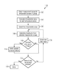
Figure 1 shows a flowchart of a method according to an
embodiment of the invention.
Figure 2 shows a block diagram of a monitoring system
according to an embodiment of the invention.
Detailed Description
The illustration in the drawing is schematic. It is noted
that in different figures, similar or identical elements are
provided with the same reference numerals or with reference
numerals which differ only within the first digit.
Figure 1 shows a flowchart of a method 100 of detecting a
temperature sensor failure in a turbine system according to
an embodiment of the invention. More specifically, the
turbine system, i.e. a gas/steam turbine, comprises a
plurality of temperature sensors (thermocouples) arranged in
groups within the turbine system, e.g. a group of burner tip
temperature sensors and a group of exhaust nozzle temperature
sensors.
The method 100 begins at step 102 where individual
measurement values from each temperature sensor in one of the
CA 03013822 2018-08-07
WO 2017/137218 PCT/EP2017/050918
-11-
groups of temperature sensors are obtained. The measurement
values from each single sensor within the group typically
have the form of a series of measurement values (or samples)
separated in time by a predetermined amount, such as 1 second
or 1 minute.
At step 104, a characteristic value, preferably a standard
deviation, an average, an exponential average or an integral
is calculated for each temperature sensor. In this regard,
measurement values from the particular temperature sensor
corresponding to a certain period of time, such as the last
minutes, are used.
At step 106, one of the calculated characteristic values is
15 selected as a first characteristic value. This corresponds to
selecting a first temperature sensor for testing.
At step 108, the maximum value among all other characteristic
values (of the group) are determined. That is, the maximum
20 value of the characteristic values except for the selected
characteristic value is determined.
Now, at step 110, it is determined whether the selected
characteristic value is larger than the maximum value
multiplied with a predetermined factor between 4 and 5.
If this is the case, the temperature sensor corresponding to
the selected characteristic value is deemed defective and the
method proceeds to step 112, where measures are taken to
notify the operator of the turbine system of the failure,
e.g. by activating an alarm, sending a Message, or in any
other suitable manner. Thereafter, the method proceeds to
step 114.
On the other hand, if the selected characteristic value is
not larger than the maximum value multiplied with the
CA 03013822 2018-08-07
WO 2017/137218 PCT/EP2017/050918
-12-
predetermined factor, the temperature sensor is deemed to he
working correctly and the method proceeds to step 114.
At step 114, it is checked whether all characteristic values
have been selected, i.e. if all temperature sensors have been
checked. As this was the first characteristic value, the
answer is no and the method proceeds to step 118, where
another characteristic value (next characteristic value) is
selected. Thereafter, steps 108, 110, 112 (only if yes in
step 110), and 114 are repeated for the selected next
characteristic value.
When it is determined in step 114 that all temperature
sensors have been tested, the method ends at step 116.
Preferably, the method is repeated for another group of
temperature sensors. Furthermore, the method may be repeated
at a later stage as part of a continuous monitoring of the
turbine system.
The core of the method 100 according to this embodiment is
that it is determined whether a characteristic value that
represents the variation in the measurement values during a
predetermined period of time is significantly larger than the
other characteristic values within the group of temperature
sensors. Since the temperature sensors in one group are
supposed to be exposed to comparable temperatures during
steady state operation of the turbine, such determination
implies that the particular sensor is behaving significantly
different than the other comparable temperature sensors.
Figure 2 shows a block diagram of a monitoring system
according to an embodiment of the invention. The shown system
comprises a monitoring device (or monitoring station) 205, a
first turbine plant 210, a second turbine plant 220, and a
third turbine plant 230. The first turbine plant comprises a
controller Cl and three turbine systems T11, T12 and T13. The
CA 03013822 2018-08-07
WO 2017/137218 PCT/EP2017/050918
-13-
controller Cl is in communication with the turbines T11, T12
and 113 and receives measurement values from temperature
sensors in each turbine T11, T12, 113 and transmits control
signals to the turbines T11, T12 and T13. Similarly, the
second turbine plant 220 comprises a controller C2 and three
turbine systems 121, T22 and T23, and the third turbine plant
230 comprises a controller C3 and four turbine systems T31,
132, 133, and T34. As a general note, more turbine plants may
be added and the number of turbine systems per plant may vary
from what is shown in Figure 2.
The device 205 is in communication with each of the turbine
plants 210, 220 and 230 via a communication unit, such as a
network interface, and receives the measurement values
collected by the respective controllers Cl, C2 and C3,
preferably in a continuous manner. The received measurement
values are stored in a suitable storage unit and processed in
accordance with the method described above in conjunction
with Figure 1. If the processing reveals a defective
temperature sensor in one of the turbine systems T11, 112,
113, T21, 122, T23, 131, 132, T33, T34, a notification unit
transmits a corresponding notification message to the
operator of the relevant turbine plant 210, 220, 230, such
that proper action can be taken, i.e. replacing the defective
thermocouple.
Accordingly, the plant operator can rely on being notified in
case of a defective temperature sensor in one of the plant
turbines. Thereby, the cumbersome labor associated with the
study of printed temperature curves or unreliable messages
from the controllers Cl, C2, C3 is no lunge/ necessary.
It is noted that the term "comprising" does not exclude other
elements or steps and the use of the articles "a" or "an"
does not exclude a plurality. Also elements described in
association with different embodiments may be combined. It is
CA 03013822 2018-08-07
WO 2017/137218
PCT/EP2017/050918
-14-
further noted that reference signs in the claims are not to
be construed as limiting the scope of the claims.
CA 03013822 2018-08-07
WO 2017/137218
PCT/EP2017/050918
-15-
List of reference numerals:
100 Method
102 Method step
104 Method step
106 Method step
108 Method step
110 Method step
112 Method step
114 Method step
116 Method step
118 Method step
205 Monitoring device
210 Turbine plant
220 Turbine plant
230 Turbine plant