Note: Descriptions are shown in the official language in which they were submitted.
PROCESS FOR REDUCTION OF SULFIDE FROM WATER AND WASTEWATER
RELATED APPLICATIONS
This application claims priority under 35 U.S.C. 119(e) from the following
U.S.
provisional application: Application Serial No. 62/295182 filed on February
15, 2016.
TECHNICAL FIELD
This application is directed to the treatment of water and wastewater.
BACKGROUND
Natural and industrial processes produce sulfide in the environment. Sulfide
found in the
nature is primarily produced by biological process under anaerobic conditions
and exists as free
hydrogen sulfide (H2S) at pH below 7Ø Under alkaline condition, it exists as
bisulfide (HS
)/sulfide (S2) ions. Biogenic H2S is encountered in groundwater, swamp and
marshes, sewage,
natural gas deposit, etc. Sources of sulfide in wastewater from industry
include coal processing,
oil and gas refining, and metals and mining operations. From aesthetic,
health, ecological, and
industrial view points, sulfide containing water must be treated carefully
prior to discharge.
Furthermore, with the increasing interest in water reuse, membrane (NF/RO)
processes are
becoming very popular. Elemental sulfur produced from sulfide is a potential
threat for
membrane fouling. In order to protect membrane, sulfide must be reduced to a
very low level
(preferably to non-detect), prior to the membrane process.
Several sulfide treatment alternatives including stripping, oxidation with
chlorine,
hydrogen peroxide, ozone, permanganate; chemical precipitation, adsorption,
and biological
processes are available. Each process has a niche guided by the water quality,
flow, process
objectives, and applicability. Because of convenience, process reliability,
and flexibility,
chemical oxidation with hydrogen peroxide is becoming popular. However, in
order for complete
oxidation of sulfide to sulfate, a high dosage of hydrogen peroxide is
required, which often
makes the process economically unfavorable. Accordingly, there is a need for
an improved cost
effective method which would oxidize sulfide to sulfate without generating any
elemental sulfur.
SUMMARY
The instant application is directed towards methods for removing sulfide from
a
wastewater stream. In one embodiment, the pH of the wastewater stream is
adjusted to
between 7.0 and 8Ø A first oxidizing agent is mixed with the wastewater
stream, oxidizing the
sulfide to elemental sulfur. The wastewater stream is then softened by mixing
lime with the
wastewater stream. The addition of lime further raises the pH of the
wastewater stream to 10.0
or higher, and converts the elemental sulfur to soluble sulfide (S2) and/or
thio-suflate. Calcium
1
CA 3014119 2020-03-17
CA 03014119 2018-08-08
WO 2017/142899 PCT/US2017/017896
carbonate is precipitated and sulfide (S2) and/or thio-suflate is adsorbed
thereon. Thereafter,
the wastewater stream is directed to a solids-liquid separation process, which
separates the
calcium carbonate and adsorbed sulfide (S2) and/or thio-sulfate from the
wastewater stream.
The solids-liquid separator produces an effluent that includes residual
elemental sulfur (usually
expressed as S2" under alkaline condition). The effluent is then mixed with a
second oxidizing
agent, which oxidizes the residual elemental sulfur to sulfate, producing a
treated effluent.
In another embodiment, a two-step oxidation process for removing sulfide from
a
wastewater stream is provided. In the first step, an oxidation reagent is
mixed with the
wastewater stream. At least some of the sulfide is oxidized to elemental
sulfur. Thereafter, a
softening reagent is added to the wastewater stream. The softening agent
increases the pH of
the wastewater stream. The increase in pH converts the elemental sulfur to
soluble sulfide (S2)
and/or thio-sulfate, and causes hardness compounds to precipitate. Soluble
sulfide and/or thio-
sulfate thereafter adsorbs onto the hardness compound. After the first step,
the wastewater
stream is directed to a solids-liquid separator. The solids-liquid separator
removes the
hardness compound having the sulfide and/or thio-sulfate adsorbed thereon and
producing an
effluent that includes residual elemental sulfur. In the second step, an
oxidizing reagent is
mixed with the effluent from the solids-liquid separator, causing the residual
elemental sulfur to
be converted to sulfate. After the second step, the wastewater stream may be
further treated or
discharged.
BRIEF DESCRIPTION OF THE DRAWINGS
Figure 1 depicts one embodiment of the methods described herein.
Figure 2 depicts a second embodiment of the methods described herein.
Figure 3 depicts another embodiment of the methods described herein.
DETAILED DESCRIPTION
The objective of this invention is to develop a cost effective sulfide
treatment technology.
The basic concept includes a two-step oxidation process which would oxidize
sulfide to sulfate;
calcium and magnesium removal by lime-soda softening; removal of elemental
sulfur generated
in the 1s1 step oxidation process by adsorption onto calcium carbonate sludge
produced during
the softening; complete oxidation of residual sulfide to sulfate in the 2nd
step oxidation process;
post neutralization; sludge treatment and disposal.
One of the novel features of this invention is to completely remove sulfide
from the water
in a cost effective manner. The other novel feature is to protect the RO/NF
membrane from
sulfur/sulfide fouling by completely removing this contaminant by the
oxidation as well as by the
co-precipitation and adsorption process (adsorption onto CaCO3 sludge formed
in the softening
process).
2
CA 03014119 2018-08-08
WO 2017/142899 PCT/US2017/017896
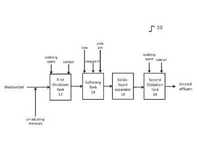
Turning to the figures, Figure 1 depicts one embodiment 10 of the methods
disclosed
herein. A wastewater containing sulfide is provided. If the pH of the
wastewater is outside the
range of 7.0 to 8.0, it is adjusted to 7.0 to 8Ø The wastewater is directed
to a first oxidation
tank 12. In a preferred embodiment, first oxidation tank 12 is a closed top
tank with a vent
connection for the exhaust gas. In the first oxidation tank 12, 'the
wastewater is mixed with
hydrogen peroxide. In a preferred embodiment, the weight ratio between
peroxide and sulfide is
0.8:1. Furthermore, an iron catalyst may be added in first oxidation tank 12.
In some
embodiments, the iron catalyst is ferric chloride or ferric sulfate.
The sulfide in the wastewater is oxidized by the hydrogen peroxide in the
presence of
the iron catalyst to elemental sulfur. Some sulfate may also be produced. The
objective of
adding iron as a catalyst is to enhance the oxidation reaction kinetics. Thus,
the chemical
reaction in the 1st stage oxidation process, at pH 7.0-8.0, is:
H2S +H202 ¨> S + 2H20
The effluent from the first oxidation tank 12 is directed to a softening tank
14. Lime is
added to softening tank 14 to adjust the pH above 10, and preferably between
10.0 and 10.5. In
some embodiments, soda ash may also be added. The addition of lime to
softening tank 14
further causes calcium carbonate (CaCO3) to precipitate. In some embodiments,
magnesium
hydroxide (Mg(OH)2) precipitates or co-precipitates with the calcium
carbonate. In some
embodiments, the wastewater may further include magnesium, which may be
removed via
.. precipitation by adjusting the pH in softening tank 14 to between 10.8 and
11.2.
Under alkaline conditions, insoluble elemental sulfur produced in first
oxidation tank 12
will be converted to soluble sulfide (S2-) and thio-sulfate in softening tank
14. The soluble
sulfide and thio-sulfate are adsorbed onto the CaCO3 or Mg(OH)2sludge. The
concentrations of
sulfide and thio-sulfate depend on the raw water quality and hydrogen peroxide
dosage. The
contents of softening tank 14 are directed to a separator 16. In a preferred
embodiment,
separator 16 is a clarifier. In some embodiments, softening tank 14 and
separator 16 may be
combined in a single softening clarifier unit. Separator 16 separates the
precipitated sludge and
produces an effluent.
The effluent from the separator 16 is directed to a second oxidation tank 18.
Hydrogen
peroxide is added to second oxidation tank 18. In some embodiments, an iron
catalyst may
also be added to second oxidation tank 18. It is noted that no additional
benefit of adding an
iron catalyst was observed for wastewaters with a pH above 10.5. In second
oxidation tank 18,
oxidation of residual elemental sulfur (expressed as sulfide ion under
alkaline condition) to
sulfate occurs by following the reaction:
S2- + 4H202 ¨> S042- + 4H20
In some embodiments, the recommended weight ratio of H202 to sulfide is
between 5:1 and 6.1.
However, the ratio depends on the water quality.
3
CA 03014119 2018-08-08
WO 2017/142899 PCT/US2017/017896
Figure 2 depicts another embodiment 20 of the methods described herein.
Wastewater
containing sulfide is directed to a first reactor 22. An oxidation reagent is
mixed with the
wastewater stream. At least some of the sulfide in the wastewater stream is
oxidized. In a
preferred embodiment, the oxidation reagent is hydrogen peroxide. An iron
catalyst may also
be added in the first reactor 22.
After the sulfide is oxidized, a softening reagent is added to the wastewater.
In some
embodiments, the softening reagent is lime. The softening agent increases the
pH of the
wastewater. As a result, hardness compounds precipitate from the wastewater,
and the
elemental sulfur is converted to sulfide and/or thio-sulfate. The sulfide
and/or thio-sulfate
adsorbs onto the precipitated hardness compounds.
After the softening step, the wastewater is directed to a solids-liquid
separator 24. The
precipitated hardness compounds on which sulfide and/or thio-sulfate are
adsorbed are
removed, producing an effluent that includes residual elemental sulfur.
The effluent is directed to a second reactor 26. An oxidizing reagent is mixed
with the
effluent. The oxidizing agent may be the same oxidizing reagent as used in the
first reactor 22
or may be a different oxidizing reagent. In a preferred embodiment, the
oxidizing reagent used
in the second reactor is hydrogen peroxide. The oxidizing reagent causes the
residual
elemental sulfur to be converted to sulfate.
The wastewater stream with sulfate from the second reactor may then be further
treated.
For example, in some embodiments, the wastewater may have its pH adjusted
lower and may
be passed through a filter 28. Filter 28 may remove any additional suspended
solids.
Examples of filters that may be used for Filter 28 include multi media
filters, sand filters,
microfilters, and ultrafilters. After being treated by filter 28, the
wastewater may be further
treated by reverse osmosis or nanofiltration for recovery. It may also be
released.
In other embodiments, the wastewater may be further treated after leaving
second
reactor 26 to remove additional contaminants. For example, the wastewater may
be sent to
tank 27. Sulfuric or hydrochloric acid may be added to adjust the pH to
between 7.0 and 8Ø A
predetermined dosage of hypochlorite may be added to tank 27 as a disinfectant
and to remove
ammonia present in the water. The dosage of hypochlorite depends on the water
quality.
However, the residual free chlorine in the pH adjustment tank may be
maintained at 0.5 mg/L to
ensure complete breakpoint chlorination. The wastewater may then be filtered
via filter 28 as
described above.
Figure 3 provides a third embodiment 30 of the methods described herein.
Wastewater
containing sulfide is provided. If necessary, the pH of the wastewater is
adjusted so that the pH
is between 7.0 and 8Ø The wastewater is directed to a first stage oxidation
tank 32. An
oxidizing reagent and an iron catalyst are added to the first stage oxidation
tank 32. In preferred
embodiments, the oxidizing reagent is hydrogen peroxide and the iron catalyst
is ferric chloride
or ferric sulfate. Sulfide in the wastewater is oxidized to elemental sulfur
as described above.
4
CA 03014119 2018-08-08
WO 2017/142899 PCT/US2017/017896
Effluent from first stage oxidation tank 32 is directed to softening reaction
tank 34. Lime
is added to adjust the pH to above 10, and preferably to between 10.0 and
10.5. If magnesium
removal is desirable, the pH may be raised to between 10.8 and 11.2. If
necessary, soda ash
may additionally be added. The alkaline conditions result in hardness
compounds precipitating.
Insoluble elemental sulfur produced in the first stage oxidation tank 32 are
further converted to
sulfide and thio-sulfate, which will adsorb onto the precipitated hardness.
Some embodiments
may further include addition of a coagulant to aid in coagulating the
precipitated hardness.
The precipitant is removed via a solids-liquids separator 36. Any solids-
liquids separator
may be utilized. In some embodiments, the solids-liquid separator 36 is a
clarifier. In some
embodiments, sludge removed in solids-liquid separator 36 may be recycled to
softening
reaction tank 34, may be directed to a sludge holding tank 44, may be directed
to a filter press
46, or may be treated by any combination thereof. In embodiments including a
filter press 46, a
filter cake may be produced for disposal, while filtrate produced in filter
press 46 may be
recycled to softening reaction tank 34. Removal of solids via the solids
separator includes the
removal of sulfide (S2) and/or thio-sulfate adsorbed onto CaCO3 from the
wastewater stream.
This has an added benefit of reducing the tendency of any membrane separation
unit that may
optionally be included downstream to foul.
The effluent from solids-liquids separator 36 is directed to a second stage
oxidation tank
38. An oxidizing agent is added to second stage oxidation tank 38, oxidizing
residual elemental
sulfur to sulfate, as discussed above. In a preferred embodiment, the
oxidizing agent is
hydrogen peroxide. If the pH is less than 10.5, an iron catalyst, such as, for
example, ferric
chloride or ferric sulfate, may also be added.
After oxidization, the effluent from the second stage oxidation tank is
directed to a pH
adjustment tank 40. Acid is added to lower the pH to between 7.0 and 8Ø
Examples of acids
that may be used include, but are not limited to, hydrochloric acid and
sulfuric acid. In some
embodiments, hypochlorite may further be added to pH adjustment tank 40 to
disinfect the
water and remove ammonia that may be in the water.
The effluent from the pH adjustment tank 40 is directed to a filter 42. In
some
embodiments, a filter aid is added prior to filtering. The filter 42 removes
residual suspended
solids generated in the process. Examples of appropriate filters that may be
used include, but
are not limited to, multi media filters, sand filters, microfilters, and
ultrafilters. After filtration, the
treated water may be discharged or further treated, such as by reverse osmosis
or nano
filtration.
Tests were undertaken using the methods described herein. Equal samples from a
common wastewater were treated. One sample was treated with prior art one
stage oxidation
process, while a second sample was treated the two-stage processes disclosed
herein.
5
CA 03014119 2018-08-08
WO 2017/142899 PCT/US2017/017896
The results of those tests are shown below:
Treatment Hydrogen Effluent Sulfide Hydrogen
Total Savings
Peroxide Concentration peroxide cost
(between single
Dosage (mg/I as S-2) ($/year) and two stage
(as 100% pure) process)
Single Stage
Single Stage 1050 mg/I <1 $13,800,000
(detection limit
<0.1)
Two Stage
First Stage 210 mg/I <1 $2,800,000
(detection limit
<0.1)
Second Stage 200 mg/I <0.5 $2,800,000
(detection limit
<0.1)
Savings ($/year)
$8,200,000
Table 1: Results in comparison tests between prior art methods and methods
disclosed
herein.
As seen in Table 1, for a single stage oxidation process, about 1,050 mg/L of
hydrogen
peroxide was required to reduce sulfide from 210 mg/L to <0.1mg/L (sulfide
detection limit for
the analytical method was <0.1 mg/L), and the associated estimated cost for
hydrogen
peroxide is US$13.80 MM/year. For a two stage oxidation process, the total
hydrogen peroxide
requirement was about 410 mg/L to achieve <0.5 mg/L of sulfide (sulfide
detection limit for this
analytical method was <0.1 mg/L) in the treated water, and the associated
estimated cost for
hydrogen peroxide is US$ 5.60 MM/year. Based on a flow of 4,920 gpm and an
influent sulfide
concentration of 210 mg/L (as S2-), the cost for the above two scenarios are
estimated. It should
be noted, however, that the chemical cost is a function of flow and the water
quality. A cost
comparison between the two processes indicates that the process discussed in
this invention
(two stage oxidation, and co-precipitation and adsorption) will save chemical
(hydrogen
peroxide) cost by more than US$8.0 MM per year.
In another test, synthetic wastewater was prepared with the components shown
in Table
2, below:
Contaminant Concentration
Calcium (mg/L Ca) 820
Magnesium (mg/L Mg) 270
Sodium (mg/L Na) 1900
Alkalinity (mg/L CaCO3) 450
Chloride (mg/L Cl) 4900
Sulfate (mg/L SO4)
TDS (mg/L) 8500
Table 2: Concentrations of contaminants in synthetic wastewater.
The synthetic wastewater was used to prepare sludge. The synthetic wastewater
was
further used to test the methods disclosed herein. This sample comprised two
liters of the
synthetic wastewater disclosed in Table 2. In addition to the components shown
in Table 2, the
6
CA 03014119 2018-08-08
WO 2017/142899 PCT/US2017/017896
sample further included 200 mg/L sulfide. The second sample was then treated
for sulfide
removal pursuant to the methods discussed herein. After softening, the
supernatant from the
softener was split into two samples. One sample was subjected to the second
stage oxidation
using a peroxide to sulfur ratios of 5:1, while the second sample was
subjected to the second
stage oxidation using a peroxide to sulfur ratio of 8:1. The results are shown
in Table 3, below.
First Stage Softening 5:1 H202 8:1 H202
Oxidation Supernatant Second Stage Second Stage
Effluent Effluent Effluent
TSS (mg/L) 204 22 17
Dissolved 880
Calcium (mg/L
Ca)
Sulfide (mg/L S2- < 1 < 1 <0.1 <0.5
Sulfate (mg/L 28.7 28.6 41.1 58.4
SO4)
Sulfur (mg/L 5) 34.3 30.4 7.9 <0.1
Table 3: Results of Two Stage Softening
The results of this study confirmed that a 1:1 ratio of hydrogen peroxide to
sulfide was
sufficient for oxidation to elemental sulfur. Softening was performed and
showed to remove the
majority of the sulfur according to the analytical analysis of the filter
cake. The remaining sulfur
in the supernatant was fully oxidized to sulfate using a target hydrogen
peroxide ratio of 8:1
(240 mg/L) based on previously obtained sulfur results.
The present invention may, of course, be carried out in other ways than those
specifically set forth herein without departing from essential characteristics
of the invention. The
present embodiments are to be considered in all respects as illustrative and
not restrictive, and
all changes coming within the meaning and equivalency range of the appended
claims are
intended to be embraced therein.
7