Note: Descriptions are shown in the official language in which they were submitted.
CA 03014136 2018-08-09
WO 2017/207580
PCT/EP2017/063055
-1-
AEROSOL GENERATING ARTICLE WITH HEAT DIFFUSER
The present invention relates to a heated aerosol-generating article for use
with an aerosol-
generating device, and to an aerosol-generating system comprising the aerosol-
generating article
and an aerosol-generating device.
One type of aerosol-generating system is an electrically operated aerosol-
generating
system. Known handheld electrically operated aerosol-generating systems
typically comprise an
aerosol-generating device comprising a battery, control electronics and an
electric heater for
heating an aerosol-generating article designed specifically for use with the
aerosol-generating
device. In some examples, the aerosol-generating article comprises an aerosol-
forming
substrate, such as a tobacco rod or a tobacco plug, and the heater contained
within the aerosol-
generating device is inserted into or around the aerosol-forming substrate
when the aerosol-
generating article is inserted into the aerosol-generating device.
In existing systems, it may be difficult to evenly heat the aerosol-forming
substrate with the
electric heater. This may lead to some areas of the aerosol-forming substrate
being over-heated
and may lead to some areas of the aerosol-forming substrate being under-
heated. Both may
make it difficult to maintain consistent aerosol characteristics. This may be
a particular issue with
aerosol-generating articles in which the aerosol-forming substrate is a liquid
aerosol-forming
substrate, since depletion of the aerosol-forming substrate may cause one or
more parts of the
aerosol-generating article to overheat.
It would be desirable to provide an aerosol-generating article that
facilitates even heating of
an aerosol-forming substrate.
According to a first aspect of the present invention there is heated aerosol-
generating article
for use with an electrically-operated aerosol-generating device, the article
having a mouth end
and a distal end upstream from the mouth end, the article comprising: a heat
diffuser at the distal
end of the article; and an aerosol-forming substrate downstream of the heat
diffuser, wherein the
heat diffuser comprises a non-combustible porous body for absorbing heat from
an electric
heating element such that, in use, air drawn through the aerosol-generating
article from the distal
end to the mouth end is heated by the heat absorbed in the porous body.
Advantageously, in use, the heat diffuser absorbs heat from a heating element
and transfers
it to air drawn through the heat diffuser so that the air can heat the aerosol-
forming substrate
downstream of the heat diffuser primarily by convection. This may provide more
even heating of
the aerosol-forming substrate relative to existing systems in which the
aerosol-forming substrate
is heated primarily by conduction from the heating element. For example, it
may reduce or
prevent areas of local high temperature, or "hot spots", from occurring in the
aerosol-forming
substrate that may otherwise be caused by conductive heating. This may be of
particular benefit
when the aerosol-forming substrate is a liquid aerosol-forming substrate,
since the heat diffuser
CA 03014136 2018-08-09
WO 2017/207580
PCT/EP2017/063055
-2-
may help to prevent overheating that may otherwise result from depletion of
the aerosol-forming
substrate. For example, where the aerosol-forming substrate comprises a liquid
aerosol-forming
substrate held in a liquid retention medium, the heat diffuser may help to
reduce or prevent
overheating of the aerosol-forming substrate or the liquid retention medium ,
even when it is dry.
Additionally, by providing the heat diffuser as part of the aerosol-generating
article, the heat
diffuser may be easily disposed of along with the aerosol-generating article.
This may be
advantageous over systems in which a heat diffuser is separate from the
aerosol-generating
article, since the heat diffuser is replaced with a new one each time the
article is replaced thus
preventing over use.
io
As used herein, the term "heated aerosol-generating article" refers to an
article comprising
an aerosol-generating substrate that, when heated, releases volatile compounds
that can form
an aerosol.
The aerosol-generating article is preferably configured to be removably
coupled to an
aerosol-generating device. The article may be disposable or reusable.
As used herein, the term "porous" is intended to encompass materials that are
inherently
porous as well as substantially non-porous materials that are made porous or
permeable through
the provision of a plurality of holes. The porous body may be formed from a
plug of porous
material, for example a ceramic or metal foam. Alternatively, the porous body
may be formed
from a plurality of solid elements between which a plurality of apertures are
provided. For
example, the porous body may comprise a bundle of fibres, or a lattice of
interconnected
filaments. The porous material must have pores of a sufficient size that air
can be drawn through
the porous body through the pores. For example, the pores in the porous body
may have an
average transverse dimension of less than about 3.0 mm, more preferably less
than about 1.0
mm, most preferably less than about 0.5 mm. Alternatively or in addition, the
pores may have an
average transverse dimension that is greater than about 0.01 mm. For example,
the pores may
have an average transverse dimension that is between about 0.01 mm and about
3.0 mm, more
preferably between about 0.01 mm and about 1.0 mm, and most preferably between
about 0.01
mm and about 0.5 mm.
As used herein, the term "pores" relates to regions of a porous article that
are devoid of
material. For example, a transverse area of porous body will comprise portions
of the material
forming the body and portions that are voids between the portions of material.
The average transverse dimension of the pores is calculated by taking the
average of the
smallest transverse dimension of each of the pores. The pore sizes may be
substantially constant
along the length of the porous body. Alternatively, the pore sizes may vary
along the length of
the porous body.
CA 03014136 2018-08-09
WO 2017/207580
PCT/EP2017/063055
-3-
As used herein, the term "transverse dimension" refers to a dimension that is
in a direction
which is substantially perpendicular to the longitudinal direction of the
porous body or of the
aerosol-generating article.
The porosity distribution of the porous body may be substantially uniform.
That is, the pores
within the porous body may be distributed substantially evenly over the
transverse area of the
porous body. The porosity distribution may differ across the transverse area
of the porous body.
That is, the local porosity in one or more sub-areas of the transverse area
may be greater than
the local porosity in one or more other sub-areas of the transverse area. For
example, the local
porosity in one or more sub-areas of the transverse area may be between 5
percent and 80
io percent greater than the local porosity in one or more other sub-areas
of the transverse area.
This may enable a flow of air through the porous body to be
As used herein, the term "transverse area " relates to an area of the porous
body that is in
a plane generally perpendicular to the longitudinal dimension of the porous
body. For example,
the porous body may be a rod and the transverse area may be a cross-section of
the rod taken
at any length along the rod, or the transverse area may be an end face of the
rod.
As used herein, the term "porosity" refers to the volume fraction of void
space in a porous
article. As used herein, the term "local porosity" refers to the fraction of
pores within a sub-area
of the porous body.
By varying the porosity distribution, air flow through the porous body may be
altered as
desired, for example to provide improved aerosol characteristics. For example,
this porosity
distribution may be varied according to the air flow characteristics of an
aerosol-generating
system, or the temperature profile of a heating element, with which the heat
diffuser is intended
for use.
In some examples, the local porosity may be lower towards a centre portion of
the porous
body. With this arrangement, the air flow through the centre portion of the
porous body is
decreased relative to the periphery of the porous body. This may be
advantageous depending
on the temperature profile of the heating element or on the airflow
characteristics of the aerosol-
generating system with which the heat diffuser is intended for use. For
example, this arrangement
may be of particular benefit when used with an internal heating element
positioned in use towards
a central portion of the heat diffuser, since it may allow for increased heat
transfer from the heating
element to the porous body.
In other examples, the local porosity may be greater towards a centre portion
of the porous
body. This arrangement may enable increased air flow through the centre of the
porous body
and may be advantageous depending on the temperature profile of the heating
element or on the
airflow characteristics of the aerosol-generating system with which the heat
diffuser is intended
for use. For example, this arrangement may be of particular benefit when used
with an external
CA 03014136 2018-08-09
WO 2017/207580
PCT/EP2017/063055
-4-
heating element positioned in use around the periphery of the heat diffuser,
since it may allow for
increased heat transfer from the heating element to the porous body.
The porous body may be formed from a heat storage material.
As used herein, the term "heat storage material" refers to a material having a
high heat
capacity. With this arrangement, the porous body may act as a heat reservoir,
allowing the heat
diffuser to absorb and store heat from the heating element and to subsequently
release the heat
over time to the aerosol-forming substrate, via air drawn through the porous
body.
Where the porous body is formed from a heat storage material, preferably, the
porous body
is formed from a material having a specific heat capacity of at least 0.5
J/g.K, preferably at least
0.7 J/g.K, more preferably at least 0.8 J/g.K at 25 degrees Celsius and
constant pressure. As the
specific heat capacity of a material is effectively a measure of the
material's ability to store thermal
energy, forming the porous body from a material having a high heat capacity
may allow the porous
body to provide a large heat reservoir for heating air drawn through the heat
diffuser without
substantially increasing the weight of an aerosol-generating system with which
the heat diffuser
is intended for use.
The porous body may be formed from any suitable material or materials. Where
the porous
body is formed from a heat storage material, suitable materials include, but
are not limited to,
glass fibre, glass mat, ceramic, silica, alumina, carbon, and minerals, or any
combination thereof.
The heat storage material may be thermally insulating. As used herein, the
term "thermally
insulating" refers to a material having a thermal conductivity of less than
100 W/m.K, preferably
less than 40 W/m.K, or less than 10 W/m.K at 23 degrees Celsius and a relative
humidity of 50%.
This may result in a heat diffuser with a higher thermal inertia relative to
thermally conductive heat
diffusers to reduce variations in the temperature of air drawn through the
porous body caused by
temperature fluctuations in the heating element. This may result in more
consistent aerosol
characteristics.
The porous body may be thermally conductive. As used herein, the term
"thermally
conductive" refers to a material having a thermal conductivity of at least 10
W/m.K, preferably at
least 40 W/m.K, more preferably at least 100 W/m.K at 23 degrees Celsius and a
relative humidity
of 50%. Where the porous body is thermally conductive, preferably, the porous
body is formed
from a material having a thermal conductivity of at least 40 W/m.K, preferably
at least 100 W/m.K,
more preferably at least 150 W/m.K, and most preferably at least 200 W/m.K at
23 degrees
Celsius and a relative humidity of 50%.
Advantageously, this may reduce the thermal inertia of the heat diffuser and
allow the
temperature of the heat diffuser to quickly adjust to changes in the
temperature of the heating
element, for example where the heating element is heated according to a
heating regime which
changes over time, while still allowing the air drawn through the porous body
to be evenly heated.
Further, by having a high thermal conductivity, the thermal resistance through
the porous body
CA 03014136 2018-08-09
WO 2017/207580
PCT/EP2017/063055
-5-
will be lower. This may allow the temperature of portions of the porous body
which are remote
from the heating element in use to be at a similarly high temperature as the
portions of the porous
body which are closest to the heating element in use. This may provide for
particularly efficient
heating of air drawn through the porous body.
Where the porous body is thermally conductive, preferably, the porous body is
formed from
a material having a thermal conductivity of at least 40 W/m.K, preferably at
least 100 W/m.K, more
preferably at least 150 W/m.K, most preferably at least 200 W/m.K at 23
degrees Celsius and a
relative humidity of 50%.
Where the porous body is thermally conductive, suitable thermally conductive
materials
include, but are not limited to, aluminium, copper, zinc, steel, silver,
thermally conductive
polymers, or any combination or alloy thereof.
In some embodiments, the porous body is formed from a heat storage material
which is
also thermally conductive, such as aluminium.
As porous bodies have a high surface-area-to-volume ratio, the heat diffuser
may allow
quick and efficient heating of air drawn through the porous body. This may
allow for homogenous
heating of air drawn through the porous body and, consequently, more even
heating of an aerosol-
forming substrate downstream of the heat diffuser.
In preferred embodiments, the porous body has a surface area-to-volume ratio
of at least
to 1, preferably at least 100 to 1, more preferably of at least 500 to 1.
Advantageously, this
20
may provide a compact heat diffuser while allowing for particularly efficient
transfer of thermal
energy from the heating element to air drawn through the porous body. This may
lead to quicker,
and homogenous heating of air drawn through the porous body and, consequently,
more even
heating of an aerosol-forming substrate downstream of the heat diffuser
relative to porous bodies
having lower surface area to volume ratios.
In preferred embodiments, the porous body has a high specific surface area.
This is a
measure of the total surface area of a body per unit of mass. Advantageously,
this may provide
a low mass heat diffuser with a large surface area for efficient transfer of
thermal energy from the
heating element to air drawn through the porous body. For example, the porous
body may have
a specific surface area of at least 0.01 m2 per gram, preferably at least 0.05
m2 per gram, more
preferably at least 0.1 m2 per gram, most preferably at least 0.5 m2 per gram.
The porous body preferably has an open cell porosity of between about 60
percent to about
90 percent void volume to material volume.
In some embodiments, the porous body has a low resistance to draw. That is,
the porous
body may offer a low resistance to the passage of air through the heat
diffuser. In such examples,
the porous body does not substantially affect the resistance to draw of an
aerosol-generating
system with which the heat diffuser is intended for use. In some embodiments,
the resistance to
draw (RTD) of the porous body is between about 10 to 130 mm H20, preferably
between about
CA 03014136 2018-08-09
WO 2017/207580
PCT/EP2017/063055
-6-
40 to 100 mm H20. The RTD of a specimen refers to the static pressure
difference between the
two ends of the specimen when it is traversed by an air flow under steady
conditions in which the
volumetric flow is 17.5 millilitres per second at the output end. The RTD of a
specimen can be
measured using the method set out in ISO Standard 6565:2002 with any
ventilation blocked.
The porous body may be configured to be penetrated by an electric heating
element forming
part of an aerosol-generating device when the heat diffuser is coupled to the
aerosol-generating
device. The term "penetrated" is used to mean that the heating element at
least partially extends
into the porous body. Thus, the heating element may be sheathed within the
porous body. With
this arrangement, by the act of penetration, the heating element is brought
into close proximity to,
io
or contact with, the porous body. This may increase heat transfer between the
heating element
and the porous body and, consequently, to air drawn through the porous body
relative to
examples in which the porous body is not penetrated by the heating element.
The heating element may conveniently be shaped as a needle, pin, rod, or blade
that may
be inserted into the heat diffuser. The aerosol-generating device may comprise
more than one
heating element and in this description reference to a heating element means
one or more heating
elements.
The porous body may define a cavity or hole for receiving the electric heating
element when
the heat diffuser is coupled to the aerosol-generating device.
In any of the above embodiments, the porous body may be rigid.
The porous body may be pierceable by the heating element when the heat
diffuser is
coupled to the aerosol-generating device. For example, the porous body may
comprise a foam,
such as a polymer, metal or ceramic foam, that is pierceable by the heating
element.
In any of the above embodiments, the electric heating element may be provided
as part of
an aerosol-generating device with which the heat diffuser is intended for use,
or as part of the
aerosol-generating article, for example as part of the heat diffuser.
In some embodiments, the aerosol-generating article may comprise an electric
heating
element thermally coupled to the porous body. In such embodiments, the porous
body is
arranged to absorb heat from the heating element and transfer it to air drawn
through the porous
body. With this arrangement, the heating element can be easily replaced by
replacing the article.
The electric heating element may comprise one or more external heating
elements, one or
more internal heating elements, or one or more external heating elements and
one or more
internal heating elements. As used herein, the term "external heating element"
refers to a heating
element that is positioned outside of the article when in use. As used herein,
the term "internal
heating element" refers to a heating element that is positioned at least
partially within the article
when in use.
The one or more external heating elements may comprise an array of external
heating
elements arranged around the periphery of the heat diffuser, for example on
the outer surface of
CA 03014136 2018-08-09
WO 2017/207580
PCT/EP2017/063055
-7-
the porous body. In certain examples, the external heating elements extend
along the longitudinal
direction of the article. With this arrangement, the heating elements may
extend along the same
direction in which the article is inserted into and removed from a cavity in
an aerosol-generating
device. This may reduce interference between the heating elements and the
aerosol-generating
device relative to devices in which the heating elements are not aligned with
the length of the
article. In some embodiments, the external heating elements extend along the
length direction of
the article and are spaced apart in the circumferential direction. Where the
heating element
comprises one or more internal heating elements, the one or more internal
heating elements may
comprise any suitable number of heating elements. For example, the heating
element may
io comprise a single internal heating element. The single internal heating
element may extend along
the longitudinal direction of the heat diffuser.
Where the electric heating element forms part of the heat diffuser, the heat
diffuser may
further comprise one or more electrical contacts by which the electric heating
element is
connectable to a power source, for example a power source in the aerosol-
generating device.
The electric heating element may be an electrically resistive heating element.
The electric heating element may comprise a susceptor in thermal contact with
the porous
body. The electric heating element may be a susceptor forming part of the heat
diffuser.
Preferably, the susceptor is embedded in the porous body.
As used herein, the term `susceptor' refers to a material that can convert
electromagnetic
energy into heat. When located within a fluctuating electromagnetic field,
eddy currents induced
in the susceptor cause heating of the susceptor. As the susceptor is in
thermal contact with the
heat diffuser, the heat diffuser is heated by the susceptor.
In such embodiments, the article is designed to engage with an electrically-
operated
aerosol-generating device comprising an induction heating source. The
induction heating source,
or inductor, generates the fluctuating electromagnetic field for heating a
susceptor located within
the fluctuating electromagnetic field. In use, the article engages with the
aerosol-generating
device such that the susceptor is located within the fluctuating
electromagnetic field generated by
the inductor.
The susceptor may be in the form of a pin, rod, or blade. The susceptor
preferably has a
length of between 5 mm and 15 mm, for example between 6 mm and 12 mm, or
between 8 mm
and 10 mm. The susceptor preferably has a width of between 1 mm and 5 mm and
may have a
thickness of between 0.01 mm and 2 mm. for example between 0.5 mm and 2 mm. A
preferred
embodiment of susceptor may have a thickness of between 10 micrometres and 500
micrometres,
or even more preferably between 10 and 100 micrometers. If the susceptor has a
constant cross-
section, for example a circular cross-section, it has a preferable width or
diameter of between 1
mm and 5 mm.
CA 03014136 2018-08-09
WO 2017/207580
PCT/EP2017/063055
-8-
The susceptor may be formed from any material that can be inductively heated
to a
temperature sufficient to generate an aerosol from the aerosol-forming
substrate. Preferred
susceptors comprise a metal or carbon. A preferred susceptor may comprise a
ferromagnetic
material, for example ferritic iron, or a ferromagnetic steel or stainless
steel. A suitable susceptor
may be, or comprise, aluminium. Preferred susceptors may be formed from 400
series stainless
steels, for example grade 410, or grade 420, or grade 430 stainless steel.
Different materials will
dissipate different amounts of energy when positioned within electromagnetic
fields having similar
values of frequency and field strength. Thus, parameters of the susceptor such
as material type,
length, width, and thickness may all be altered to provide a desired power
dissipation within a
io known electromagnetic field.
Preferred susceptors may be heated to a temperature in excess of 250 degrees
Centigrade.
Suitable susceptors may comprise a non-metallic core with a metal layer
disposed on the non-
metallic core, for example metallic tracks formed on a surface of a ceramic
core.
A susceptor may have a protective external layer, for example a protective
ceramic layer or
protective glass layer encapsulating the susceptor. The susceptor may comprise
a protective
coating formed by a glass, a ceramic, or an inert metal, formed over a core of
the susceptor.
The heat diffuser may contain a single susceptor. Alternatively, the heat
diffuser may
comprise more than one susceptor.
The aerosol-forming substrate may be a solid aerosol-forming substrate.
Alternatively, the
aerosol-forming substrate may comprise both solid and liquid components. The
aerosol-forming
substrate may comprise tobacco. The aerosol-forming substrate may comprise a
tobacco-
containing material containing volatile tobacco flavour compounds which are
released from the
substrate upon heating. The aerosol-forming substrate may comprise a non-
tobacco material.
The aerosol-forming substrate may comprise tobacco-containing material and non-
tobacco
containing material.
The aerosol-forming substrate may further comprise an aerosol former that
facilitates the
formation of a dense and stable aerosol. Examples of suitable aerosol formers
are glycerine and
propylene glycol.
The aerosol-forming substrate may comprise a solid aerosol-forming substrate.
The
aerosol-forming substrate may comprise a tobacco-containing material
containing volatile
tobacco flavour compounds which are released from the substrate upon heating.
The aerosol-
forming substrate may comprise a non-tobacco material. .
The aerosol-forming substrate may include at least one aerosol-former. As used
herein,
the term 'aerosol former' is used to describe any suitable known compound or
mixture of
compounds that, in use, facilitates formation of an aerosol. Suitable aerosol
formers are
substantially resistant to thermal degradation at the operating temperature of
the aerosol-
generating article. Examples of suitable aerosol formers are glycerine and
propylene glycol.
CA 03014136 2018-08-09
WO 2017/207580
PCT/EP2017/063055
-9-
Suitable aerosol-formers include, but are not limited to: polyhydric alcohols,
such as propylene
glycol, triethylene glycol, 1,3-butanediol and glycerine; esters of polyhydric
alcohols, such as
glycerol mono-, di- or triacetate; and aliphatic esters of mono-, di- or
polycarboxylic acids, such
as dimethyl dodecanedioate and dimethyl tetradecanedioate. Preferred aerosol
formers are
polyhydric alcohols or mixtures thereof, such as propylene glycol, triethylene
glycol, 1,3-
butanediol and, most preferred, glycerine. The aerosol-forming substrate may
comprise a single
aerosol former. Alternatively, the aerosol-forming substrate may comprise a
combination of two
or more aerosol formers. The aerosol-forming substrate may have an aerosol
former content of
greater than 5 percent on a dry weight basis. The aerosol-forming substrate
may have an aerosol
io former content of between approximately 5 percent and approximately 30
percent on a dry weight
basis. The aerosol-forming substrate may have an aerosol former content of
approximately 20
percent on a dry weight basis.
The aerosol-forming substrate may comprise a liquid aerosol-forming substrate.
The liquid
aerosol-forming substrate may comprise a nicotine solution. The liquid aerosol-
forming substrate
preferably comprises a tobacco-containing material comprising volatile tobacco
flavour
compounds which are released from the liquid upon heating. The liquid aerosol-
forming substrate
may comprise a non-tobacco material. The liquid aerosol-forming substrate may
include water,
solvents, ethanol, plant extracts and natural or artificial flavours.
Preferably, the liquid aerosol-
forming substrate further comprises an aerosol former.
As used herein, the term "liquid aerosol-forming substrate" refers to an
aerosol-forming
substrate that is in a liquid rather than a solid form. A liquid aerosol-
forming substrate may be at
least partially absorbed by a liquid retention medium. A liquid-aerosol-
forming substrate includes
an aerosol-forming substrate in the form of a gel.
In some embodiments, the aerosol-generating article comprises a liquid aerosol-
forming
substrate and a liquid retention medium for retaining the liquid aerosol-
forming substrate.
As used herein, the term "liquid retention medium" refers to a component that
is capable of
releasably retaining a liquid aerosol-forming substrate. The liquid retention
medium may be, or
may comprise, a porous or fibrous material that absorbs or otherwise retains a
liquid aerosol-
forming substrate that it is brought into contact with while allowing the
liquid aerosol-forming
substrate to be released by vaporisation.
The liquid retention medium preferably comprises an absorbent material, for
example an
absorbent polymeric material. Examples of suitable liquid retention materials
include fibrous
polymers and porous polymers such as open-cell foams. The liquid retention
medium may
comprise a fibrous cellulose acetate or a fibrous cellulose polymer. The
liquid retention medium
may comprise a porous polypropylene material. Suitable materials capable of
retaining a liquid
will be known to the skilled person.
CA 03014136 2018-08-09
WO 2017/207580
PCT/EP2017/063055
-10-
The liquid retention medium is either located within an air-flow path through
the heated
aerosol-generating article or defines at least a portion of an air-flow path
through the aerosol-
generating article. Preferably, one or more holes defined through the liquid
retention medium
define a portion of the air-flow path through the heated aerosol-generating
article between the
distal end of the article and the mouth end of the article.
The liquid retention medium may be in the form of a tube having a central
lumen. Walls of
the tube would then be formed from, or comprise, a suitable liquid-retention
material.
The liquid aerosol-forming substrate be incorporated into the liquid retention
medium
immediately prior to use. For example, a dose of liquid aerosol-forming
substrate may be injected
io into the liquid retention medium immediately prior to use.
Articles according to the invention may comprise a liquid aerosol-forming
substrate
contained within a frangible capsule. The frangible capsule may be located
between the distal
end and the mid-point of the article.
As used herein, the term "frangible capsule" refers to a capsule that is
capable of containing
a liquid aerosol-forming substrate and releasing the liquid aerosol-forming
substrate when broken
or ruptured. The frangible capsule may be formed from, or comprise, a brittle
material that is easily
broken by a user to release its liquid aerosol-forming substrate contents. For
example the capsule
may be broken by external force such as finger pressure, or by contact with a
piercing or rupturing
element.
The frangible capsule is preferably spheroid, for example spherical or ovoid,
having a
maximum dimension of between 2 mm and 8 mm, for example between 4 mm and 6 mm.
The
frangible capsule may contain a volume of between 20 and 300 microlitres, for
example between
and 200 microlitres. Such a range may provide between 10 and 150 puffs of
aerosol to a user.
The frangible capsule may have a brittle shell, or may be shaped to facilitate
rupture when
25 subjected to external force. The frangible capsule may be configured to
be ruptured by application
of external force. For example, the frangible capsules may be configured to
rupture at a specific
defined external force, thereby releasing the liquid-aerosol-forming
substrate. The frangible
capsule may be configured with a weakened or brittle portion of its shell to
facilitate rupture. The
frangible capsule may be arranged for engagement with a piercing element for
breaking the
30 capsule and releasing the liquid aerosol-forming substrate. Preferably
the frangible capsule has
a burst strength of between about 0.5 and 2.5 kilograms force (kgf), for
example between 1.0 and
2.0 kgf.
The shell of the frangible capsule may comprise a suitable polymeric material,
for example
a gelatin based material. The shell of the capsule may comprise a cellulose
material or a starch
material.
Preferably, the liquid aerosol-forming substrate is releasably contained
within the frangible
capsule and the article further comprises a liquid retention medium located in
proximity to the
CA 03014136 2018-08-09
WO 2017/207580
PCT/EP2017/063055
-11-
frangible capsule for retaining the liquid aerosol-forming substrate within
the article after its
release from the frangible capsule.
The liquid retention medium is preferably capable of absorbing between 105%
and 110%
of the total volume of liquid contained within the frangible capsule. This
helps to prevent leakage
of liquid aerosol-forming substrate from the article after the frangible
capsule has been broken to
release its contents. It is preferred that the liquid retention medium is
between 90% and 95%
saturated after release of the liquid aerosol-forming substrate from the
frangible capsule.
In preferred embodiments, the aerosol-forming substrate is a liquid aerosol-
forming
substrate and the article further comprises a frangible capsule containing the
liquid aerosol-
io forming substrate, and a liquid retention medium downstream of the heat
diffuser and arranged
to absorb the liquid aerosol-forming substrate when the frangible capsule is
broken.
The frangible capsule may be located within the porous carrier material. For
example, the
porous carrier material may. Preferably, the porous carrier material is
provided in the form of a
liquid retention tube and the frangible capsule is located within the lumen of
the tube.
The frangible capsule may be located adjacent to the liquid retention medium
within the
article such that the liquid-aerosol-forming substrate released from the
frangible capsule can
contact and be retained by the liquid retention medium. The frangible capsule
may be located
within the liquid retention medium. For example, the liquid retention medium
may comprise a plug
of material in which the capsule is embedded. Preferably, article comprises a
tubular liquid
retention medium and the frangible capsule containing the liquid aerosol-
forming substrate is
located within the lumen of the tubular liquid retention medium.
Where the aerosol-forming substrate is a solid aerosol-forming substrate, the
solid aerosol-
forming substrate may be immediately downstream of the heat diffuser. For
example, the solid
aerosol-forming substrate may abut the heat diffuser. In other embodiments,
the solid aerosol-
forming substrate may be spaced apart in the longitudinal direction from the
heat diffuser.
In certain preferred embodiments, the aerosol-forming substrate is a liquid
aerosol-forming
substrate and the article further comprises a liquid retention medium for
retaining the liquid
aerosol-forming substrate. In such embodiments, the liquid retention medium
may be
immediately downstream of the heat diffuser. For example, the liquid retention
medium may abut
the heat diffuser. In other embodiments, the liquid retention medium may be
spaced apart in the
longitudinal direction from the heat diffuser.
In one particular embodiment, the aerosol-forming substrate is a liquid
aerosol-forming
substrate and the article further comprises a liquid retention medium for
retaining the liquid
aerosol-forming substrate, the liquid retention medium being spaced apart in
the longitudinal
direction from the heat diffuser.
With this arrangement, conductive heat transfer between the heat diffuser and
the liquid
retention medium may be reduced. This may further reduce or prevent areas of
local high
CA 03014136 2018-08-09
WO 2017/207580
PCT/EP2017/063055
-12-
temperature, or "hot spots", from occurring in the liquid retention medium
that may otherwise be
caused by conductive heating.
Aerosol-generating articles according to the present invention may further
comprise a
support element may be located immediately downstream of the aerosol-forming
substrate or,
where the article comprises a liquid retention medium for retaining a liquid
aerosol-forming
substrate, immediately downstream of the liquid retention medium. The support
element may
abut the aerosol-forming substrate or the liquid retention medium.
The support element may be formed from any suitable material or combination of
materials.
For example, the support element may be formed from one or more materials
selected from the
io group consisting of: cellulose acetate; cardboard; crimped paper, such
as crimped heat resistant
paper or crimped parchment paper; and polymeric materials, such as low density
polyethylene
(LDPE). In a preferred embodiment, the support element is formed from
cellulose acetate. The
support element may comprise a hollow tubular element. For example, the
support element
comprises a hollow cellulose acetate tube. The support element preferably has
an external
diameter that is approximately equal to the external diameter of the aerosol-
generating article.
The support element may have an external diameter of between approximately
5 millimetres and approximately 12 millimetres, for example of between
approximately
5 millimetres and approximately 10 millimetres or of between approximately 6
millimetres and
approximately 8 millimetres. For example, the support element may have an
external diameter
of 7.2 millimetres +/-10 percent.
The support element may have a length of between approximately 5 millimetres
and
approximately 15 mm. In a preferred embodiment, the support element has a
length of
approximately 8 millimetres.
An aerosol-cooling element may be located downstream of the aerosol-forming
substrate,
for example an aerosol-cooling element may be located immediately downstream
of a support
element, and may abut the support element. The aerosol-cooling element may be
located
immediately downstream of the aerosol-forming substrate or, where the article
comprises a liquid
retention medium for retaining a liquid aerosol-forming substrate, immediately
downstream of the
liquid retention medium. For example, the aerosol-cooling element may abut the
aerosol-forming
substrate or the liquid retention medium.
The aerosol-cooling element may have a total surface area of between
approximately 300
square millimetres per millimetre length and approximately 1000 square
millimetres per millimetre
length. In a preferred embodiment, the aerosol-cooling element has a total
surface area of
approximately 500 square millimetres per millimetre length.
The aerosol-cooling element preferably has a low resistance to draw. That is,
the aerosol-
cooling element preferably offers a low resistance to the passage of air
through the aerosol-
CA 03014136 2018-08-09
WO 2017/207580
PCT/EP2017/063055
-13-
generating article. Preferably, the aerosol-cooling element does not
substantially affect the
resistance to draw of the aerosol-generating article.
The aerosol-cooling element may comprise a plurality of longitudinally
extending channels.
The plurality of longitudinally extending channels may be defined by a sheet
material that has
been one or more of crimped, pleated, gathered and folded to form the
channels. The plurality of
longitudinally extending channels may be defined by a single sheet that has
been one or more of
crimped, pleated, gathered and folded to form multiple channels.
Alternatively, the plurality of
longitudinally extending channels may be defined by multiple sheets that have
been one or more
of crimped, pleated, gathered and folded to form multiple channels.
io
In some embodiments, the aerosol-cooling element may comprise a gathered sheet
of
material selected from the group consisting of metallic foil, polymeric
material, and substantially
non-porous paper or cardboard. In some embodiments, the aerosol-cooling
element may
comprise a gathered sheet of material selected from the group consisting of
polyethylene (PE),
polypropylene (PP), polyvinylchloride (PVC), polyethylene terephthalate (PET),
polylactic acid
(PLA), cellulose acetate (CA), and aluminium foil.
In a preferred embodiment, the aerosol-cooling element comprises a gathered
sheet of
biodegradable material. For example, a gathered sheet of non-porous paper or a
gathered sheet
of biodegradable polymeric material, such as polylactic acid or a grade of
Mater-Bi (a
commercially available family of starch based copolyesters).
In a particularly preferred
embodiment, the aerosol-cooling element comprises a gathered sheet of
polylactic acid.
The aerosol-cooling element may be formed from a gathered sheet of material
having a
specific surface area of between approximately 10 square millimetres per
milligram and
approximately 100 square millimetres per milligram weight. In some
embodiments, the aerosol-
cooling element may be formed from a gathered sheet of material having a
specific surface area
of approximately 35 mm2/mg.
The aerosol-generating article may comprise a mouthpiece located at the mouth
end of the
aerosol-generating article. The mouthpiece may be located immediately
downstream of an
aerosol-cooling element and may abut the aerosol-cooling element. The
mouthpiece may be
located immediately downstream of the aerosol-forming substrate or, where the
article comprises
a liquid retention medium for retaining a liquid aerosol-forming substrate,
immediately
downstream of the liquid retention medium. In such embodiments, the mouthpiece
may abut the
aerosol-forming substrate, or the liquid retention medium. The mouthpiece may
comprise a filter.
The filter may be formed from one or more suitable filtration materials. Many
such filtration
materials are known in the art. In one embodiment, the mouthpiece may comprise
a filter formed
from cellulose acetate tow.
The mouthpiece preferably has an external diameter that is approximately equal
to the
external diameter of the aerosol-generating article. The mouthpiece may have
an external
CA 03014136 2018-08-09
WO 2017/207580
PCT/EP2017/063055
-14-
diameter of a diameter of between approximately 5 millimetres and
approximately 10 millimetres,
for example of between approximately 6 millimetres and approximately 8
millimetres. In a
preferred embodiment, the mouthpiece has an external diameter of 7.2
millimetres +/- 10%.
The mouthpiece may have a length of between approximately 5 millimetres and
approximately 20 millimetres. For example, the mouthpiece may have a length of
from about 7
mm to about 12 mm.
The elements of the aerosol-forming article may be circumscribed by an outer
wrapper, for
example in the form of a rod. The wrapper may circumscribe at least a
downstream portion of
the heat diffuser. In some embodiments, the wrapper circumscribes the heat
diffuser along
io substantially the entire length of the heat diffuser. The outer wrapper
may be formed from any
suitable material or combination of materials. Preferably, the outer wrapper
is non-porous.
The aerosol-generating article may be substantially cylindrical in shape. The
aerosol-
generating article may be substantially elongate. The aerosol-generating
article may have a
length and a circumference substantially perpendicular to the length. The
aerosol-forming
substrate or a porous carrier material in which the aerosol-forming substrate
is absorbed during
use, may be substantially cylindrical in shape. The aerosol-forming substrate
or the porous carrier
material may be substantially elongate. The aerosol-forming substrate, or the
porous carrier
material, may also have a length and a circumference substantially
perpendicular to the length.
The aerosol-generating article may have an external diameter of between
approximately
5 millimetres and approximately 12 millimetres, for example of between
approximately
6 millimetres and approximately 8 millimetres. In a preferred embodiment, the
aerosol-generating
article has an external diameter of 7.2 millimetres +/- 10 percent.
The aerosol-generating article may have a total length between approximately
30 mm and
approximately 100 mm. In one embodiment, the aerosol-generating article has a
total length of
approximately 45 mm.
The aerosol-forming substrate or, where applicable, the liquid retention
medium, may have
a length of between about 7 mm and about 15 mm. In one embodiment, the aerosol-
forming
substrate, or the liquid retention medium, may have a length of approximately
10 mm.
Alternatively, the aerosol-forming substrate, or the liquid retention medium,
may have a length of
approximately 12 mm.
The aerosol-generating substrate or liquid retention medium, preferably has an
external
diameter that is approximately equal to the external diameter of the aerosol-
generating article.
The external diameter of the aerosol-forming substrate, or the liquid
retention medium, may be
between approximately 5 mm and approximately 12 mm. In one embodiment, the
aerosol-forming
substrate, or the liquid retention medium, may have an external diameter of
approximately 7.2
mm +/- 10 percent.
In use, the heat diffuser preferably heats air drawn through it to between 200
and 220
CA 03014136 2018-08-09
WO 2017/207580
PCT/EP2017/063055
-15-
degrees Celsius. The air preferably cools to about 100 degrees in the aerosol
cooling element.
According to a second aspect of the present invention, there is provided a
heated aerosol-
generating system comprising an electrically operated aerosol-generating
device and a heated
aerosol-generating article according to any of the embodiments discussed
above.
As used herein, the term 'aerosol-generating device' relates to a device that
interacts with
an aerosol-forming substrate to generate an aerosol. An electrically operated
aerosol-generating
device is a device comprising one or more components used to supply energy
from an electrical
power supply to an aerosol-forming substrate to generate an aerosol.
An aerosol-generating device may be described as a heated aerosol-generating
device,
io
which is an aerosol-generating device comprising a heating element. The
heating element or
heater is used to heat an aerosol-forming substrate of an aerosol-generating
article to generate
an aerosol, or the solvent-evolving substrate of a cleaning consumable to form
a cleaning solvent.
An aerosol-generating device may be an electrically heated aerosol-generating
device,
which is an aerosol-generating device comprising a heating element that is
operated by electrical
power to heat an aerosol-forming substrate of an aerosol-generating article to
generate an
aerosol.
The aerosol-generating device of the aerosol-generating system may comprise: a
housing
having a cavity for receiving the aerosol-generating article and a controller
configured to control
the supply of power from a power supply to an electric heating element of the
system.
The electric heating element may form part of the aerosol-generating article,
part of the
aerosol-generating device, or both.
In certain embodiments, the electric heating element forms part of the device.
The electric heating element may comprise one or more heating elements.
In preferred embodiments, the electrically operated aerosol-generating device
comprises
an electric heating element and a housing having a cavity, and the heated
aerosol-generating
article is received in the cavity such that the heat diffuser is penetrated by
the electric heating
element. The heating element may conveniently be shaped as a needle, pin, rod,
or blade that
may be inserted into the heat diffuser.
Aerosol-generating systems according to the invention include an electric
heating element.
The electric heating element may comprise one or more external heating
elements, one or more
internal heating elements, or one or more external heating elements and one or
more internal
heating elements. As used herein, the term "external heating element" refers
to a heating element
that is positioned outside of the heat diffuser when an aerosol-generating
system comprising the
heat diffuser is assembled. As used herein, the term "internal heating
element" refers to a heating
element that is positioned at least partially within the heat diffuser when an
aerosol-generating
system comprising the heat diffuser is assembled.
CA 03014136 2018-08-09
WO 2017/207580
PCT/EP2017/063055
-16-
The one or more external heating elements may comprise an array of external
heating
elements arranged around the inner surface of the cavity. In certain examples,
the external
heating elements extend along the longitudinal direction of the cavity. With
this arrangement, the
heating elements may extend along the same direction in which the article is
inserted into and
removed from the cavity. This may reduce interference between the heating
elements and the
heat diffuser relative to devices in which the heating elements are not
aligned with the length of
the cavity. In some embodiments, the external heating elements extend along
the length direction
of the cavity and are spaced apart in the circumferential direction. Where the
heating element
comprises one or more internal heating elements, the one or more internal
heating elements may
io comprise any suitable number of heating elements. For example, the
heating element may
comprise a single internal heating element. The single internal heating
element may extend along
the longitudinal direction of the cavity.
The electric heating element may comprise an electrically resistive material.
Suitable
electrically resistive materials include but are not limited to:
semiconductors such as doped
ceramics, electrically "conductive" ceramics (such as, for example, molybdenum
disilicide),
carbon, graphite, metals, metal alloys and composite materials made of a
ceramic material and a
metallic material. Such composite materials may comprise doped or undoped
ceramics.
Examples of suitable doped ceramics include doped silicon carbides. Examples
of suitable
metals include titanium, zirconium, tantalum and metals from the platinum
group. Examples of
suitable metal alloys include stainless steel, Constantan, nickel-, cobalt-,
chromium-, aluminium-
titanium- zirconium-, hafnium-, niobium-, molybdenum-, tantalum-, tungsten-,
tin-, gallium-,
manganese- and iron-containing alloys, and super-alloys based on nickel, iron,
cobalt, stainless
steel, Timetal , iron-aluminium based alloys and iron-manganese-aluminium
based alloys.
Timetal is a registered trade mark of Titanium Metals Corporation, 1999
Broadway Suite 4300,
Denver Colorado. In composite materials, the electrically resistive material
may optionally be
embedded in, encapsulated or coated with an insulating material or vice-versa,
depending on the
kinetics of energy transfer and the external physicochemical properties
required. The heating
element may comprise a metallic etched foil insulated between two layers of an
inert material. In
that case, the inert material may comprise Kapton , all-polyimide or mica
foil. Kapton is a
registered trade mark of E.I. du Pont de Nemours and Company, 1007 Market
Street, Wilmington,
Delaware 19898, United States of America.
Where the electric heating element comprises a susceptor in thermal contact
with the
porous body of the heat diffuser, the aerosol-generating device preferably
comprises an inductor
arranged to generate a fluctuating electromagnetic field within the cavity. ;
an electrical power
supply connected to the inductor. The inductor may comprise one or more coils
that generate a
fluctuating electromagnetic field. The coil or coils may surround the cavity.
CA 03014136 2018-08-09
WO 2017/207580
PCT/EP2017/063055
-17-
Preferably the device is capable of generating a fluctuating electromagnetic
field of between
1 and 30 MHz, for example, between 2 and 10 MHz, for example between 5 and 7
MHz.
Preferably the device is capable of generating a fluctuating electromagnetic
field having a field
strength (H-field) of between 1 and 5 kA/m, for example between 2 and 3 kA/m,
for example about
2.5 kA/m.
Preferably, the aerosol-generating device is a portable or handheld aerosol-
generating
device that is comfortable for a user to hold between the fingers of a single
hand.
The aerosol-generating device may be substantially cylindrical in shape
The aerosol-generating device may have a length of between approximately 70
millimetres
io and approximately 120 millimetres.
The device may comprise a power supply for supplying electrical power to the
electric
heating element. The power supply may be any suitable power supply, for
example a DC voltage
source such as a battery. In one embodiment, the power supply is a Lithium-ion
battery.
Alternatively, the power supply may be a Nickel-metal hydride battery, a
Nickel cadmium battery,
or a Lithium based battery, for example a Lithium-Cobalt, a Lithium-Iron-
Phosphate, Lithium
Titan ate or a Lithium-Polymer battery.
The controller may be a simple switch. Alternatively the controller may be
electric circuitry
and may comprise one or more microprocessors or microcontrollers.
As used herein, the terms 'upstream' and 'downstream' are used to describe the
relative
positions of elements, or portions of elements, of the aerosol-generating
article, or aerosol-
generating device, in relation to the direction in which air is drawn through
the system during use
thereof.
As used herein, the term 'longitudinal' is used to describe the direction
between the
upstream end and the downstream end of the aerosol-generating article, or an
element thereof,
or the aerosol-generating device, and the term 'transverse' is used to
describe the direction
perpendicular to the longitudinal direction.
As used herein, the term 'diameter' is used to describe the maximum dimension
in the
transverse direction of the aerosol-generating article, or an element thereof,
or the aerosol-
generating device. As used herein, the term 'length' is used to describe the
maximum dimension
in the longitudinal direction.
As used herein, the term 'removably coupled' is used to mean that the article
and device
can be coupled and uncoupled from one another without significantly damaging
either
component. For example, the article may be removed from the device when the
aerosol-forming
substrate has been consumed.
Features described in relation to one or more aspects may equally be applied
to other
aspects of the invention. In particular, features described in relation to the
article of the first aspect
may be equally applied to the system of the second aspect, and vice versa.
CA 03014136 2018-08-09
WO 2017/207580
PCT/EP2017/063055
-18-
The invention is further described, by way of example only, with reference to
the
accompanying drawings in which:
Figure 1 shows a schematic longitudinal cross-section of an aerosol-generating
article
according to a first embodiment of the present invention;
Figure 2 shows a schematic view of an aerosol-generating system according to
an
embodiment of the invention, the system comprising the aerosol-generating
article of Figure 1;
and
Figure 3 shows a schematic longitudinal cross-section of an aerosol-generating
article
according to a second embodiment of the present invention.
io
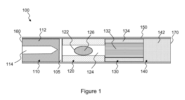
Figure 1 illustrates an aerosol-generating article 100 according to a first
embodiment of the
invention. The aerosol-generating article 100 comprises four elements arranged
in coaxial
alignment: a heat diffuser 110, a tubular liquid retention medium 120, an
aerosol-cooling element
130, and a mouthpiece 140. Each of these four elements is a substantially
cylindrical element,
each having substantially the same diameter. These four elements are arranged
sequentially and
are circumscribed by a non-porous outer wrapper 150 to form a cylindrical rod.
The aerosol-generating article 100 has a distal or upstream end 160 and a
proximal or
mouth end 170, opposite to the upstream end 160, into which a user inserts
into his or her mouth
during use. Once assembled, the total length of the aerosol-generating article
200 is about 33
mm about 45 mm and the diameter is about 7.2 mm.
The heat diffuser 110 is located at the extreme distal or upstream end 160 of
the aerosol-
generating article 100 includes a porous body 112 in the form of a cylindrical
plug of heat storage
material. The porous body 112 has a cavity in the form of a slot 114 in its
upstream end, which
is arranged to receive a blade-shaped heating element, as discussed below in
relation to Figure
2. The pores in the porous body 112 are interconnected to form a plurality of
air flow passages
extending through the porous body 112 from its upstream end to its downstream
end.
The tubular liquid retention medium 120 is located downstream of the heat
diffuser 110 and
is spaced apart from the heat diffuser 110 in the longitudinal direction of
the article 100 by a
separation 105. This may minimize the extent to which the aerosol-forming
segment 120 might
be heated by conduction from the heat diffuser 110.
The article 100 further includes a frangible capsule 122 located within the
lumen 124 of the
liquid retention medium 120. The frangible capsule 122 contains a liquid
aerosol-forming
substrate 126.
The tubular liquid retention medium 120 has a length of 8 mm and is formed
from fibrous
cellulose acetate material. The liquid retention medium has a capacity to
absorb 35 microlitres of
liquid. The lumen 124 of the tubular liquid retention medium 120 provides an
air flow path through
the liquid retention medium 120 and also acts to locate the frangible capsule
122. The material of
the liquid retention medium may be any other suitable fibrous or porous
material .
CA 03014136 2018-08-09
WO 2017/207580
PCT/EP2017/063055
-19-
The frangible capsule 122 is shaped as an oval spheroid and has the long
dimension of the
oval aligned with the axis of the lumen 124. The oval spheroid shape of the
capsule may mean
that it is easier to break than if it was circular spherical in shape, but
other shapes of capsule may
be used. The capsule 122 has an outer shell comprising a gelatin based
polymeric material
surrounding a liquid aerosol-forming substrate.
The liquid aerosol-forming substrate 126 comprises propylene glycol, nicotine
extract, and
20 weight percent water. A wide range of flavourants may be optionally added.
A wide range of
aerosol-formers may be used as alternative, or in addition to, propylene
glycol. The capsule is
about 4 mm in length and contains a volume of about 33 microlitres of liquid
aerosol-forming
io substrate.
The aerosol-cooling element 130 is located immediately downstream of and abuts
the liquid
retention medium 120. In use, volatile substances released from the aerosol-
forming substrate
126 pass along the aerosol-cooling element 130 towards the mouth end 170 of
the aerosol-
generating article 100. The volatile substances may cool within the aerosol-
cooling element 130
to form an aerosol that is inhaled by the user. In the embodiment illustrated
in Figure 1, the
aerosol-cooling element 130 comprises a crimped and gathered sheet 132 of
polylactic acid
circumscribed by a wrapper 134. The crimped and gathered sheet 132 of
polylactic acid defines
a plurality of longitudinal channels that extend along the length of the
aerosol-cooling element
130.
The mouthpiece 140 is located immediately downstream of and abuts the aerosol-
cooling
element 130. In the embodiment illustrated in Figure 1, the mouthpiece 140
comprises a
conventional cellulose acetate tow filter 142 of low filtration efficiency.
To assemble the aerosol-generating article 100, the four cylindrical elements
described
above are aligned and tightly wrapped within the outer wrapper 150. In the
embodiment illustrated
in Figure 1, the outer wrapper 150 is formed from a non-porous sheet material.
In other examples,
the outer wrapper may comprise a porous material, such as cigarette paper.
Figure 2 shows an aerosol-generating system in accordance with an embodiment
of the
present invention. The aerosol-generating system comprises the aerosol-
generating article 100,
and an aerosol-generating device 200.
The aerosol-generating device 200 includes a housing 210 defining a cavity 220
for
receiving the aerosol-generating article 100. The device 200 further includes
a heater 230
comprising a base portion 232 and a heating element in the form of a heater
blade 234 that
penetrates the heat diffuser 110 so that a portion of the heater blade 234
extends into the slot in
the porous body 112 when the article 100 is received in the cavity 220, as
shown in Figure 2. The
heater blade 234 comprises resistive heating tracks 236 for resistively
heating the heat diffuser
110. A controller 240 controls the operation of the device 200, including the
supply of electrical
current from a battery 250 to the resistive heating tracks 236 of the heater
blade 234.
CA 03014136 2018-08-09
WO 2017/207580
PCT/EP2017/063055
-20-
In the example shown in Figure 2, the frangible capsule has been ruptured
prior to insertion
of the article 100 into the cavity 220 of the device 200. Thus, the liquid
aerosol-forming substrate
is shown as having been absorbed into the liquid retention medium 120.
During use, the controller 240 supplies electrical current from the battery
250 to the resistive
heating tracks 236 to heat the heater blade 234. Thermal energy is then
absorbed by the porous
body 112 of the heat diffuser 110. Air is drawn into the device 200 through
air inlets (not shown)
and subsequently through the heat diffuser 110 and along the aerosol-
generating article 100 by
a user from the distal end 160 to the mouth end 170 of the aerosol-generating
article 100. As air
is drawn through the porous body 112, the air is heated by the heat stored in
the porous body
112 before passing through the tubular liquid retention medium 120 to heat the
liquid aerosol-
forming substrate in the liquid retention medium 120. Preferably, the air is
heated by the heat
diffuser to between 200 and 220 degrees Celsius. The air then preferably cools
to about 100
degrees as it is drawn through the aerosol cooling element.
During the heating cycle, at least some of the one or more volatile compounds
within the
aerosol-generating substrate are evaporated. The vaporised aerosol-forming
substrate is
entrained in the air flowing through the liquid retention medium 120 and
condenses within the
aerosol-cooling element 130 and the mouthpiece portion 140 to form an
inhalable aerosol, which
exits the aerosol-generating article 100 at its mouth end 170.
Figure 3 shows an aerosol-generating article 300 according to a second aspect
of the
present invention. The aerosol-generating article 300 has a similar structure
to the aerosol-
generating article 100 of Figure 1 and where the same features are present
like reference
numerals have been used. As with the aerosol-generating article 100 of Figure
1, the aerosol-
generating article 300 comprises a heat diffuser 310õ an aerosol-cooling
element 330, and a
mouthpiece 340 arranged in coaxial alignment and circumscribed by a non-porous
outer wrapper
350 to form a cylindrical rod: However, unlike the generating article 100 of
Figure 1, the aerosol-
generating article 300 includes a solid aerosol-forming substrate in the form
of a cylindrical plug
320 of homogenised tobacco-based material 322 including an aerosol former such
as, for
example, glycerine, wrapped in plug wrap 324. As with the liquid retention
tube of the first article
100, the aerosol-forming substrate plug 320 is positioned downstream of the
heat diffuser 310
and upstream of the aerosol-cooling element 330 and is circumscribed by the
wrapper 350.
During use, air is drawn through the heat diffuser 310 and the aerosol-forming
substrate plug 320.
Use of the aerosol-generating article 300 is otherwise the same as discussed
above in relation to
Figures 1 and 2.
The specific embodiments and examples described above illustrate but do not
limit the
invention. It is to be understood that other embodiments of the invention may
be made and the
specific embodiments and examples described herein are not exhaustive.
CA 03014136 2018-08-09
WO 2017/207580
PCT/EP2017/063055
-21-
For example, although the examples shown in Figures 1 and 2 illustrate that
the article 100
includes one frangible capsule, in other examples, two or more frangible
capsules may be
provided.
Furthermore, although the example shown in Figure 2 illustrates the heating
element as a
heating blade arranged to extend into the heat diffuser, the heating element
may be provided as
one or more heating elements extending around the periphery of the cavity.
Additionally or
alternatively, the heating element may comprise a susceptor located within the
heat diffuser. For
example, a blade-shaped susceptor may be located within the heat diffuser, in
contact with the
porous body. One or both ends of the susceptor may be sharpened or pointed to
facilitate insertion
io into the heat diffuser.