Language selection

Search

Patent 3014300 Summary

Third-party information liability

Some of the information on this Web page has been provided by external sources. The Government of Canada is not responsible for the accuracy, reliability or currency of the information supplied by external sources. Users wishing to rely upon this information should consult directly with the source of the information. Content provided by external sources is not subject to official languages, privacy and accessibility requirements.

Claims and Abstract availability

Any discrepancies in the text and image of the Claims and Abstract are due to differing posting times. Text of the Claims and Abstract are posted:

  • At the time the application is open to public inspection;
  • At the time of issue of the patent (grant).
(12) Patent Application: (11) CA 3014300
(54) English Title: METHOD FOR FASTENING A COMPOSITE POLE TO THE GROUND COMPRISING A SLEEVE-FORMED FASTENING ELEMENT
(54) French Title: METHODE POUR ATTACHER UN POTEAU COMPOSITE AU SOL COMPRENANT UN ELEMENT D'ATTACHE EN MANCHON
Status: Examination Requested
Bibliographic Data
(51) International Patent Classification (IPC):
  • E04H 12/22 (2006.01)
  • E02D 27/42 (2006.01)
(72) Inventors :
  • FJELDE, OLE GUNNAR (Norway)
  • FJELDE, TORBJORN (Norway)
  • HABAKK, SIGURD (Norway)
(73) Owners :
  • COMROD AS (Norway)
(71) Applicants :
  • COMROD AS (Norway)
(74) Agent: SMART & BIGGAR LP
(74) Associate agent:
(45) Issued:
(86) PCT Filing Date: 2017-02-16
(87) Open to Public Inspection: 2017-08-24
Examination requested: 2022-02-14
Availability of licence: N/A
(25) Language of filing: English

Patent Cooperation Treaty (PCT): Yes
(86) PCT Filing Number: PCT/NO2017/050040
(87) International Publication Number: WO2017/142419
(85) National Entry: 2018-08-09

(30) Application Priority Data:
Application No. Country/Territory Date
20160270 Norway 2016-02-16

Abstracts

English Abstract

The invention relates to a fastening element (10) for fastening a hollow composite pole (8) to the ground (4) at a location where a slit-formed opening (6) is present in the ground (4), wherein the fastening element (10) has a lower end portion (12) that is configured for being positioned in the slit-formed opening (6), wherein a conical portion of the composite pole (8) is abutting a conical upper portion (18) of the fastening element (10). The invention also relates to a method for fastening a hollow composite pole (8) to the ground (4).


French Abstract

L'invention concerne un élément de fixation (10) conçu pour fixer un poteau composite creux (8) au sol (4), en un emplacement auquel une ouverture en forme de fente (6) est pratiquée dans le sol (4). L'élément de fixation (10) présente une partie d'extrémité inférieure (12) qui est conçue pour être positionnée dans l'ouverture en forme de fente (6). Une partie conique du poteau composite (8) vient en butée contre une partie supérieure conique (18) de l'élément de fixation (10). L'invention concerne également un procédé de fixation au sol (4) d'un poteau composite creux (8).

Claims

Note: Claims are shown in the official language in which they were submitted.


6

claims

1. Fastening element (10) for fastening a hollow composite pole (8) for
overhead
power lines to the ground (4) at a location where a slit-formed opening (6) is
pre-
sent in the ground (4), wherein the fastening element (10) has a lower end por-

tion (12) that is configured for being positioned in the slit-formed opening
(6),
wherein the fastening element (10) has a conical upper portion (18), wherein,
in
operational use of the fastening element (10), a conical portion of the
composite
pole (8) is configured for moving over the conical upper portion (18) of the
fas-
tening element (10) until abutment with the fastening element (10) is
established.
2. The fastening element (10) according to claim 1, wherein the lower end
portion
(12) of the fastening element (10) is circular for allowing the fastening
element
(10) to be placed in the slit formed opening (6) being circular.
3. The fastening element (10) according to claim 1 or 2, wherein the
fastening ele-
ment (10) at its lower end portion (12) is equipped with drill elements (14).
4. The fastening element (10) according to claim 3, wherein the drill
elements (14)
comprise metal.
5. The fastening element (10) according to claim 3, wherein the drill
elements (14)
comprise ceramic material.
6. Method for fastening a hollow composite pole (8) for overhead power
lines to the
ground (4), wherein the method comprises:
- making a slit-formed opening (6) in the ground (4);
- inserting the fastening element (10) in accordance with claim 1 into the
slit-
formed opening (6), and
- moving the composite pole (8) that is conical, over the fastening element
(10)
until abutment is established.
7. The method according to claim 6, wherein the method comprises fixing the
fas-
tening element (10) to the ground (4).
8. The method according to claim 6 or 7, wherein the method comprises
making the
slit-formed opening (6) by drilling into the ground (4).


7

9. The method according to claim 6 or 7, wherein the method comprises
making the
slit-formed opening (6) by hammering the fastening element (10) into the
ground
(4).
10. The method according to claim 6 to 8, wherein the method comprises
providing
the fastening element (10) in accordance with claim 3, and drilling the
fastening
element (10) into the ground.

Description

Note: Descriptions are shown in the official language in which they were submitted.


CA 03014300 2018-08-09
1 -- PCT/NO 2017/050 0," "--"
7
'Printed: 20/12/2017 DESCPAMD
,N02017050040'
1
APPARATUS AND METHOD FOR FASTENING A COMPOSITE POLE TO THE
GROUND
FIELD OF THE INVENTION
This invention relates to an apparatus for fastening a hollow composite pole
to the ground
where a slit formed opening is present in the ground. The invention also
relates to a
method for fastening a hollow composite pole to the ground.
BACKGROUND OF THE INVENTION
It is known to fasten composite poles in the ground by excavating a recess,
and thereafter
positioning the composite pole in the recess and fill in around the pole.
Regarding poles
for overhead power lines, such a method will often involve relatively large
environmental
damage, particularly when a recess is made in rock. Wlen fastening poles by
use of said
method, frost damage may occur due insufficient draining.
It is also known to mount a composite pole to a column 'raised from the
ground. The col-
umn may be made from concrete and having reinforcement that extends into the
ground.
The composite pole may be inserted over the column. If the column is made from
con-
crete, it is necessary to bring the concrete to the position of the column
often by use of a
helicopter, or make concrete at the position of the column. Both methods
comprises extra
zo costs and work.
W02004/101914 discloses a hollow pole that is drilled into a slit the ground.
Documents EP1911912A2, W02004/101914A1, G62444411 and GB2429229A show
other solutions from the prior art.
1 P2783IPC00 - description and claims. amended ea-=-= =
'AMENDED SHEET
14/12/2017

CA 03014300 2018-08-09
=
jPrinted: 20/12/2017.
iDESCPAMD PCT/NO 2017/050
NO2017050040:
2
SUMMARY OF THE INVENTION
The invention has for its objeceto remedy or to reduce at least one of the
drawbacks of
the prior art, or at least provide a useful alternative to prior art.
The object is achieved through features, which are specified in the
description below and
in the claims that follow.
The invention is defined by the independent patent claims. The dependent
claims define
advantageous embodiments of the invention.
In a first aspect, the invention relates more particularly to fastening
element in accordance
with claim 1.
io The invention concerns having a slit-formed opening, preferably
circular, in the ground,
where a fastening element is positioned in the slit-formed opening. The
fastening element
has a conical upper portion above the ground. A hollow composite pole, has a
comple-
mentary conical inner portion at its lower end, and is positioned on and
abutting the fas-
tening element.
By hollow means that the composite pole' must have an inner opening, at least
in the por-
tion that is moved over the fastening element.
The slit formed opening may be circular and formed by drilling or hammering a
body into
the ground.
The fastening element may be equipped with drill elements at its lower end
portion to en-
able the fastening element to be used as a drill.
The drill elements may comprise metal or ceramic material or combinations
thereof.
In a second aspect the invention relates more particularly to a method for
fastening a hol-
low composite pole for overhead power lines to the ground in accordance with
claim 6.
The method comprises fixing the fastening element to the ground, for instance
by adhe-
sive or a concrete based material.
The method may comprise making the slit formed opening by drilling into the
ground.
The method may comprise making the slit formed opening by hammering the
fastening
element into the ground.
2 P27831PC00 - description and claims, amended
AMENDED SHEET
14/12/2017

CA 03014300 2018-08-09
.:Printed: 20/12/2017 DESCPAM6 PCT/ NO 2017/050 NO
020170 -A50040 "17 .
3
The method comprises providing the lower end portion of the fastening element
with drill
elements and drilling the fastening element into the ground.
The fastening element may be made from composite material or metal or
combinations
thereof.
If parts of the ground that is positioned on the inner side of the slit should
loosen or where
it is advantageous to have it removed partly or fully, the material on the
inner side of the
slit may be at least partly removed.
When drilling in soil or march, it may be advantageous to have frost in the
ground to avoid
movement in the ground during drilling.
io Tests show that the drill or the fastening element must be aligned with
the vertical axes
prior to being moved into the ground.
The apparatus and method according to invention solves the problem of
fastening a hol-
low composite pole to the ground in a relatively simple and cost effective
way.
BRIEF INTRODUCTION OF THE DRAWINGS
In the following is described examples of preferred embodiments and methods
illustrated
in the ac-companying drawings, wherein:
Fig. 1 shows a vertical section of a drill and a power drill during drilling
of a slit formed
opening in the ground according to the invention;
Fig. 2 shows a vertical section of a composite pole that has been moved into
the slit
formed opening that was drilled by use of the drill in fig. 1;
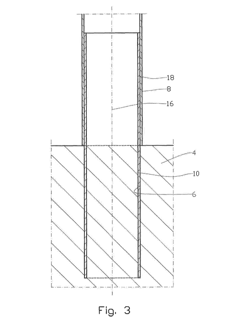
Fig. 3 shows an embodiment where a fastening element has been moved into the
slit
formed opening that is drilled by the use of the drill shown in fig. 1, and
where the fas-
tening element is fixed to the composite mast;
Fig. 4 shows another embodiment where the fastening element, at its lower
portion, is
equipped with drill bodies:
3 P2783.1PC00 - description and clams, amended an¨ '"'"` ""v
'AMENDED SHEET
'14/12/2017

CA 03014300 2018-08-09
(
r
DESCPAMD - = - PCT/ NO 2017/050 0,^
0
17 Prin- ted:-20/12/201i
NO201705004'
4 .
Fig. 5 shows a section IV-IV in fig. 4; and
Fig. 6 shows in a larger scale a segment V-V in fig. 5 of the lower portion pf
the fastening
element and a drill body.
DETAILED DESCRIPTION.OF THE EMBODIMENTS
On the drawings, the reference numeral 1 denotes a drill that by the help of a
power drill 2
is under displacement into the ground 4. The ground 4 may constitute for
example rock,
soil, or march, alternatively combination thereof.
The power drill 2 is typically aligned and is fixed to the ground 4 or another
suitable, not
lo shown device. There after the power drill 2 that may be electrically or
hydraulically driven,
displaces the drill 1 into the ground 4 while rotating the drill 1. Thus, a
slit formed opening
6 is formed in the ground 4. The drill 1 is then removed from the slit formed
opening 6. _
A composite pole 8 that has been moved into the slit formed opening 6 is shown
in fig. 2.
Additional fixing of the composite pole 8 to the ground 4 may be achieved by
inserting
grouting, fixing compound or other material (not shown) in between the
composite pole 8
and the ground 4.
In an embodiment of the invention, shown in fig. 3, a sleeve formed fastening
element 10
is positioned in the slit formed opening 6. Additional fixing of the fixing
element 10 to the
ground 4 may be carried out as described for the composite pole 8. A composite
pole 8
that is conical inside is placed about the fastening element 10 that has a
conical upper
portion 18, and moved against the fastening element until abutment is
established.
In some cases, as when the ground 4 mainly constitutes suitable soil, the
fixing element
10 may be forced into the ground 4 by hammering.
In a further alternative embodiment as shown in fig. 4, the fastening element
10 is by its
lower end portion 12 equipped with several drill elements 14. The section IV-
IV in fig 5
shows a possible distribution of the drill elements 14 about the centre axis
16 of the fas-
tening element 10. The drill elements may be made from material from the
fastening ele-
ment 10 or constitute other materials that is fixed to the fastening element
10.
4 P27831PC00 - description and claims, amended '-""r. "'""
AMENDED SHEET
14/12/2017

CA 03014300 2018-08-09
;Printed: 20/12/2017 PCT/ NO 2017/050 1DESCPAMD
NO2017050040'
A typical drill element 14 is shown in fig. 6 where the drill element 14 that
constitutes hard
metal, is braced to the in use lover end portion lower end portion 12 of the
fixing element
10.
The fixing element 10 shown in fig. 4 is shown in two parts where in use an
upper portion
5 18 that is fixed to the composite pole 8 is fixed to the in use lower
portion 22 of the fixing
element 10 by a flange connection 20. The lower portion 22 is here drilled
into the ground
4.
It should be noted that the above-mentioned embodiments illustrate rather than
limit the
invention, and that those skilled in the art will be able to design many
alternative embodi-
113 ments without departing from the scope of the appended claims. In the
claims, any refer-
ence signs placed between parentheses shall not be construed as limiting the
claim. Use
of the verb "comprise" and its conjugations does not exclude the presence of
elements or
steps other than those stated in a claim. The article "a" or "an" preceding an
element does
not exclude the presence of a plurality of such elements. The mere fact that
certain
measures are recited in mutually different dependent claims doe-, not indicate
that a com-
bination of these measures cannot be used to advantage.
5 P27631PC00 - description and claims, amended a'--=
AMENDED SHEET
'14/12/2017

Representative Drawing
A single figure which represents the drawing illustrating the invention.
Administrative Status

For a clearer understanding of the status of the application/patent presented on this page, the site Disclaimer , as well as the definitions for Patent , Administrative Status , Maintenance Fee  and Payment History  should be consulted.

Administrative Status

Title Date
Forecasted Issue Date Unavailable
(86) PCT Filing Date 2017-02-16
(87) PCT Publication Date 2017-08-24
(85) National Entry 2018-08-09
Examination Requested 2022-02-14

Abandonment History

There is no abandonment history.

Maintenance Fee

Last Payment of $277.00 was received on 2024-01-18


 Upcoming maintenance fee amounts

Description Date Amount
Next Payment if small entity fee 2025-02-17 $100.00
Next Payment if standard fee 2025-02-17 $277.00

Note : If the full payment has not been received on or before the date indicated, a further fee may be required which may be one of the following

  • the reinstatement fee;
  • the late payment fee; or
  • additional fee to reverse deemed expiry.

Patent fees are adjusted on the 1st of January every year. The amounts above are the current amounts if received by December 31 of the current year.
Please refer to the CIPO Patent Fees web page to see all current fee amounts.

Payment History

Fee Type Anniversary Year Due Date Amount Paid Paid Date
Application Fee $400.00 2018-08-09
Maintenance Fee - Application - New Act 2 2019-02-18 $100.00 2019-01-09
Registration of a document - section 124 $100.00 2019-08-09
Maintenance Fee - Application - New Act 3 2020-02-17 $100.00 2020-01-06
Maintenance Fee - Application - New Act 4 2021-02-16 $100.00 2021-01-07
Maintenance Fee - Application - New Act 5 2022-02-16 $203.59 2022-02-02
Request for Examination 2022-02-16 $814.37 2022-02-14
Maintenance Fee - Application - New Act 6 2023-02-16 $210.51 2023-01-11
Maintenance Fee - Application - New Act 7 2024-02-16 $277.00 2024-01-18
Owners on Record

Note: Records showing the ownership history in alphabetical order.

Current Owners on Record
COMROD AS
Past Owners on Record
None
Past Owners that do not appear in the "Owners on Record" listing will appear in other documentation within the application.
Documents

To view selected files, please enter reCAPTCHA code :


To view images, click a link in the Document Description column. To download the documents, select one or more checkboxes in the first column and then click the "Download Selected in PDF format (Zip Archive)" or the "Download Selected as Single PDF" button.

List of published and non-published patent-specific documents on the CPD .

If you have any difficulty accessing content, you can call the Client Service Centre at 1-866-997-1936 or send them an e-mail at CIPO Client Service Centre.


Document
Description 
Date
(yyyy-mm-dd) 
Number of pages   Size of Image (KB) 
Request for Examination / Amendment 2022-02-14 6 183
Office Letter 2022-03-18 2 203
Examiner Requisition 2023-03-30 8 430
Abstract 2018-08-09 2 70
Claims 2018-08-09 2 53
Drawings 2018-08-09 5 176
Description 2018-08-09 5 181
Representative Drawing 2018-08-09 1 36
National Entry Request 2018-08-09 5 110
International Preliminary Report Received 2018-08-10 12 480
International Search Report 2018-08-09 2 57
Cover Page 2018-08-21 1 43
Examiner Requisition 2023-12-22 5 249
Amendment 2024-04-22 8 272
Description 2024-04-22 5 254
Amendment 2023-07-27 22 780
Description 2023-07-27 5 252
Claims 2023-07-27 1 51