Note: Descriptions are shown in the official language in which they were submitted.
CA 03014339 2018-09-13
WO 2017/140666 PCT/EP2017/053272
Apparatus and Method for Stereo Filling in Multichannel Coding
Description
The present invention relates to audio signal coding and, in particular, to an
apparatus
and method for stereo filling in multichannel coding.
Audio coding is the domain of compression that deals with exploiting
redundancy and
irrelevancy in audio signals.
In MPEG USAC (see, e.g., [3]), joint stereo coding of two channels is
performed using
complex prediction, MPS 2-1-2 or unified stereo with band-limited or full-band
residual
signals. MPEG surround (see, e.g., [4]) hierarchically combines One-To-Two
(OTT) and
Two-To-Three (TTT) boxes for joint coding of multichannel audio with or
without
transmission of residual signals.
In MPEG-H, Quad Channel Elements hierarchically apply MPS 2-1-2 stereo boxes
followed by complex prediction/MS stereo boxes building a fixed 4x4 remixing
tree, (see,
e.g., [1]).
AC4 (see, e.g., [6]) introduces new 3-, 4- and 5- channel elements that allow
for remixing
transmitted channels via a transmitted mix matrix and subsequent joint stereo
coding
information. Further, prior publications suggest to use orthogonal transforms
like
Karhunen-Loeve Transform (KLT) for enhanced multichannel audio coding (see,
e.g., [7]).
For example, in the 30 audio context, loudspeaker channels are distributed in
several
height layers, resulting in horizontal and vertical channel pairs. Joint
coding of only two
channels as defined in USAC is not sufficient to consider the spatial and
perceptual
relations between channels. MPEG Surround is applied in an additional pre-/
postprocessing step, residual signals are transmitted individually without the
possibility of
joint stereo coding, e.g. to exploit dependencies between left and right
vertical residual
signals. In AC-4 dedicated N- channel elements are introduced that allow for
efficient
encoding of joint coding parameters, but fail for generic speaker setups with
more
channels as proposed for new immersive playback scenarios (7.1+4, 22.2). MPEG-
H
Quad Channel element is also restricted to only 4 channels and cannot be
dynamically
applied to arbitrary channels but only a pre-configured and fixed number of
channels.
CA 03011339 2018-08-13
WO 2017/140666 PCT/EP2017/053272
2
The MPEG-H Multichannel Coding Tool allows the creation of an arbitrary tree
of
discretely coded stereo boxes, i.e. jointly coded channel pairs, see [2].
A problem that often arises in audio signal coding is caused by quantization,
e.g., spectral
quantization. Quantization may possibly result in spectral holes. For example,
all spectral
values in a particular frequency band may be set to zero on the encoder side
as a result of
quantization. For example, the exact value of such spectral lines before
quantization may
be relatively low and quantization then may lead to a situation, where the
spectral values
.. of all spectral lines, for example, within a particular frequency band have
been set to zero.
On the decoder side, when decoding, this may lead to undesired spectral holes.
Modern frequency-domain speech/audio coding systems such as the Opus/Celt
codec of
the IETF [9], MPEG-4 (HE-)AAC [10] or, in particular, MPEG-D xHE-AAC (USAC)
[11],
offer means to code audio frames using either one long transform ¨ a long
block ¨ or eight
sequential short transforms ¨ short blocks ¨ depending on the temporal
stationarity of the
signal. In addition, for low-bitrate coding these schemes provide tools to
reconstruct
frequency coefficients of a channel using pseudorandom noise or lower-
frequency
coefficients of the same channel. In xHE-AAC, these tools are known as noise
filling and
spectral band replication, respectively.
However, for very tonal or transient stereophonic input, noise filling and/or
spectral band
replication alone limit the achievable coding quality at very low bitrates,
mostly since too
many spectral coefficients of both channels need to be transmitted explicitly.
MPEG-H Stereo Filling is a parametric tool which relies on the use of a
previous frame's
downmix to improve the filling of spectral holes caused by quantization in the
frequency
domain. Like noise filling, Stereo Filling operates directly in the MDCT
domain of the
MPEG-H core coder, see [1], [5], [8].
However, using of MPEG Surround and Stereo Filling in MPEG-H is restricted to
fixed
channel pair elements and therefore cannot exploit time-variant inter-channel
dependencies.
The Multichannel Coding Tool (MCT) in MPEG-H allows adapting to varying inter-
channel
dependencies but, due to usage of single channel elements in typical operating
configurations, does not allow Stereo Filling. The prior art does not disclose
perceptually
optimal ways to generate previous frame's downmixes in case of time-variant,
arbitrary
3
jointly coded channel pairs. Using noise filling as a substitute for stereo
filling in
combination with the MCT to fill spectral holes would lead to noise artifacts,
especially for
tonal signals.
The object of the present invention is to provide improved audio coding
concepts. The
object of the present invention is solved by an apparatus for decoding, by an
apparatus for
encoding, by a method for decoding, by a method for encoding, by a computer
program
and by an encoded multichannel signal.
An apparatus for decoding an encoded multichannel signal of a current frame to
obtain
three or more current audio output channels is provided. A multichannel
processor is
adapted to select two decoded channels from three or more decoded channels
depending
on first multichannel parameters. Moreover, the multichannel processor is
adapted to
generate a first group of two or more processed channels based on said
selected
channels. A noise filling module is adapted to identify for at least one of
the selected
channels, one or more frequency bands, within which all spectral lines are
quantized to
zero, and to generate a mixing channel using, depending on side information, a
proper
subset of three or more previous audio output channels that have been decoded,
and to
fill the spectral lines of frequency bands, within which all spectral lines
are quantized to
zero, with noise generated using spectral lines of the mixing channel.
According to embodiments, an apparatus for decoding a previous encoded
multichannel
signal of a previous frame to obtain three or more previous audio output
channels, and for
decoding a current encoded multichannel signal of a current frame to obtain
three or more
current audio output channels is provided.
The apparatus comprises an interface, a channel decoder, a multichannel
processor for
generating the three or more current audio output channels, and a noise
filling module.
The interface is adapted to receive the current encoded multichannel signal,
and to
receive side information comprising first multichannel parameters.
The channel decoder is adapted to decode the current encoded multichannel
signal of the
current frame to obtain a set of three or more decoded channels of the current
frame.
CA 3014339 2019-12-20
CA 03011339 2018-08-13
WO 2017/140666 PCT/EP2017/053272
4
The multichannel processor is adapted to select a first selected pair of two
decoded
channels from the set of three or more decoded channels depending on the first
multichannel parameters.
Moreover, the multichannel processor is adapted to generate a first group of
two or more
processed channels based on said first selected pair of two decoded channels
to obtain
an updated set of three or more decoded channels.
Before the multichannel processor generates the first pair of two or more
processed
channels based on said first selected pair of two decoded channels, the noise
filling
module is adapted to identify for at least one of the two channels of said
first selected pair
of two decoded channels, one or more frequency bands, within which all
spectral lines are
quantized to zero, and to generate a mixing channel using two or more, but not
all of the
three or more previous audio output channels, and to fill the spectral lines
of the one or
more frequency bands, within which all spectral lines are quantized to zero,
with noise
generated using spectral lines of the mixing channel, wherein the noise
filling module is
adapted to select the two or more previous audio output channels that are used
for
generating the mixing channel from the three or more previous audio output
channels
depending on the side information.
A particular concept of embodiments that may be employed by the noise filling
module
that specifies how to generate and fill noise is referred to as Stereo
Filling.
Moreover, an apparatus for encoding a multichannel signal having at least
three channels
is provided.
The apparatus comprises an iteration processor being adapted to calculate, in
a first
iteration step, inter-channel correlation values between each pair of the at
least three
channels, for selecting, in the first iteration step, a pair having a highest
value or having a
value above a threshold, and for processing the selected pair using a
multichannel
processing operation to derive initial multichannel parameters for the
selected pair and to
derive first processed channels.
The iteration processor is adapted to perform the calculating, the selecting
and the
processing in a second iteration step using at least one of the processed
channels to
derive further multichannel parameters and second processed channels.
CA 03011339 2018-08-13
WO 2017/140666 PCT/EP2017/053272
Moreover, the apparatus comprises a channel encoder being adapted to encode
channels
resulting from an iteration processing performed by the iteration processor to
obtain
encoded channels.
5
Furthermore, the apparatus comprises an output interface being adapted to
generate an
encoded multichannel signal having the encoded channels, the initial
multichannel
parameters and the further multichannel parameters and having an information
indicating
whether or not an apparatus for decoding shall fill spectral lines of one or
more frequency
bands, within which all spectral lines are quantized to zero, with noise
generated based on
previously decoded audio output channels that have been previously decoded by
the
apparatus for decoding.
Moreover, a method for decoding a previous encoded multichannel signal of a
previous
frame to obtain three or more previous audio output channels, and for decoding
a current
encoded multichannel signal of a current frame to obtain three or more current
audio
output channels is provided. The method comprises:
- Receiving the current encoded multichannel signal, and receiving
side information
comprising first multichannel parameters.
- Decoding the current encoded multichannel signal of the current
frame to obtain a
set of three or more decoded channels of the current frame.
- Selecting a first selected pair of two decoded channels from the set of
three or
more decoded channels depending on the first multichannel parameters.
- Generating a first group of two or more processed channels based on
said first
selected pair of two decoded channels to obtain an updated set of three or
more
decoded channels.
Before the first pair of two or more processed channels is generated based on
said first
selected pair of two decoded channels, the following steps are conducted:
- Identifying for at least one of the two channels of said first selected
pair of two
decoded channels, one or more frequency bands, within which all spectral lines
CA 03011339 2018-08-13
WO 2017/140666 PCT/EP2017/053272
6
are quantized to zero, and generating a mixing channel using two or more, but
not
all of the three or more previous audio output channels, and filling the
spectral
lines of the one or more frequency bands, within which all spectral lines are
quantized to zero, with noise generated using spectral lines of the mixing
channel,
wherein selecting the two or more previous audio output channels that are used
for
generating the mixing channel from the three or more previous audio output
channels is conducted depending on the side information.
Furthermore, a method for encoding a multichannel signal having at least three
channels
is provided. The method comprises:
- Calculating, in a first iteration step, inter-channel correlation
values between each
pair of the at least three channels, for selecting, in the first iteration
step, a pair
having a highest value or having a value above a threshold, and processing the
selected pair using a multichannel processing operation to derive initial
multichannel parameters for the selected pair and to derive first processed
channels.
- Performing the calculating, the selecting and the processing in a
second iteration
step using at least one of the processed channels to derive further
multichannel
parameters and second processed channels.
- Encoding channels resulting from an iteration processing performed
by the
iteration processor to obtain encoded channels. And:
- Generating an encoded multichannel signal having the encoded
channels, the
initial multichannel parameters and the further multichannel parameters and
having
an information indicating whether or not an apparatus for decoding shall fill
spectral lines of one or more frequency bands, within which all spectral lines
are
quantized to zero, with noise generated based on previously decoded audio
output
channels that have been previously decoded by the apparatus for decoding.
Moreover, computer programs are provided, wherein each of the computer
programs is
configured to implement one of the above-described methods when being executed
on a
computer or signal processor, so that each of the above-described methods is
implemented by one of the computer programs.
CA 03011339 2018-08-13
WO 2017/140666 PCT/EP2017/053272
7
Furthermore, an encoded multichannel signal is provided. The encoded
multichannel
signal comprises encoded channels and multichannel parameters and information
indicating whether or not an apparatus for decoding shall fill spectral lines
of one or more
frequency bands, within which all spectral lines are quantized to zero, with
spectral data
.. generated based on previously decoded audio output channels that have been
previously
decoded by the apparatus for decoding.
In the following, embodiments of the present invention are described in more
detail with
reference to the figures, in which:
Fig. 13 shows an apparatus for decoding according to an embodiment;
Fig. lb shows an apparatus for decoding according to another embodiment;
Fig. 2 shows a block diagram of a parametric frequency-domain decoder
according to
an embodiment of the present application;
Fig. 3 shows a schematic diagram illustrating the sequence of spectra forming
the
spectrograms of channels of a multichannel audio signal in order to ease the
understanding of the description of the decoder of Fig. 2;
Fig. 4 shows a schematic diagram illustrating current spectra out of the
spectrograms
shown in Fig. 3 for the sake of alleviating the understanding of the
description of
Fig. 2;
Fig. 5a and 5b show a block diagram of a parametric frequency-domain audio
decoder
in accordance with an alternative embodiment according to which the downmix of
the previous frame is used as a basis for inter-channel noise filling;
Fig. 6 shows a block diagram of a parametric frequency-domain audio encoder in
accordance with an embodiment;
Fig. 7 shows a schematic block diagram of an apparatus for encoding a
multichannel
signal having at least three channels, according to an embodiment;
Fig. 8 shows a schematic block diagram of an apparatus for encoding a
multichannel
signal having at least three channels, according to an embodiment;
CA 03011339 2018-08-13
WO 2017/140666 PCT/EP2017/053272
8
Fig. 9 shows a schematic block diagram of a stereo box, according to an
embodiment;
Fig. 10 shows a schematic block diagram of an apparatus for decoding an
encoded
multichannel signal having encoded channels and at least two multichannel
parameters, according to an embodiment;
Fig. 11 shows a flowchart of a method for encoding a multichannel signal
having at least
three channels, according to an embodiment;
Fig. 12 shows a flowchart of a method for decoding an encoded multichannel
signal
having encoded channels and at least two multichannel parameters, according to
an embodiment;
Fig. 13 shows a system according to an embodiment;
Fig. 14 shows in scenario (a) a generation of combination channels for a first
frame in
scenario, and in scenario (b) a generation of combination channels for a
second
frame succeeding the first frame according to an embodiment; and
Fig. 15 shows an indexing scheme for the multichannel parameters according to
embodiments.
Equal or equivalent elements or elements with equal or equivalent
functionality are
denoted in the following description by equal or equivalent reference
numerals.
In the following description, a plurality of details are set forth to provide
a more thorough
explanation of embodiments of the present invention. However, it will be
apparent to those
skilled in the art that embodiments of the present invention may be practiced
without these
specific details. In other instances, well-known structures and devices are
shown in block
diagram form rather than in detail in order to avoid obscuring embodiments of
the present
invention. In addition, features of the different embodiments described
hereinafter may be
combined with each other, unless specifically noted otherwise.
CA 03011339 2018-08-13
WO 2017/140666 PCT/EP2017/053272
9
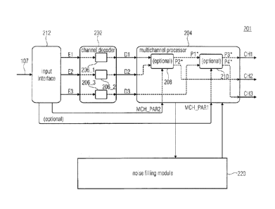
Before describing the apparatus 201 for decoding of Fig. 1a, at first, noise
filling for
multichannel audio coding is described. In embodiments, the noise filing
module 220 of
Fig. la may, e.g., be configured to conduct on or more of the technologies
below that are
described regarding noise filling for multichannel audio coding.
Fig. 2 shows a frequency-domain audio decoder in accordance with an embodiment
of the
present application. The decoder is generally indicated using reference sign
10 and
comprises a scale factor band identifier 12, a dequantizer 14, a noise filler
16 and an
inverse transformer 18 as well as a spectral line extractor 20 and a scale
factor extractor
22. Optional further elements which might be comprised by decoder 10 encompass
a
complex stereo predictor 24, an MS (mid-side) decoder 26 and an inverse TNS
(Temporal
Noise Shaping) filter tool of which two instantiations 28a and 28b are shown
in Fig. 2. In
addition, a downmix provider is shown and outlined in more detail below using
reference
sign 30.
The frequency-domain audio decoder 10 of Fig. 2 is a parametric decoder
supporting
noise filling according to which a certain zero-quantized scale factor band is
filled with
noise using the scale factor of that scale factor band as a means to control
the level of the
noise filled into that scale factor band. Beyond this, the decoder 10 of Fig.
2 represents a
multichannel audio decoder configured to reconstruct a multichannel audio
signal from an
inbound data stream 30. Fig. 2, however, concentrates on decoder's 10 elements
involved
in reconstructing one of the multichannel audio signals coded into data stream
30 and
outputs this (output) channel at an output 32. A reference sign 34 indicates
that decoder
10 may comprise further elements or may comprise some pipeline operation
control
responsible for reconstructing the other channels of the multichannel audio
signal wherein
the description brought forward below indicates how the decoder's 10
reconstruction of
the channel of interest at output 32 interacts with the decoding of the other
channels.
The multichannel audio signal represented by data stream 30 may comprise two
or more
channels. In the following, the description of the embodiments of the present
application
concentrate on the stereo case where the multichannel audio signal merely
comprises two
channels, but in principle the embodiments brought forward in the following
may be readily
transferred onto alternative embodiments concerning multichannel audio signals
and their
coding comprising more than two channels.
CA 03011339 2018-08-13
WO 2017/140666 PCT/EP2017/053272
As will further become clear from the description of Fig. 2 below, the decoder
10 of Fig. 2
is a transform decoder. That is, according to the coding technique underlying
decoder 10,
the channels are coded in a transform domain such as using a lapped transform
of the
channels. Moreover, depending on the creator of the audio signal, there are
time phases
5 during which the channels of the audio signal largely represent the same
audio content,
deviating from each other merely by minor or deterministic changes
therebetween, such
as different amplitudes and/or phase in order to represent an audio scene
where the
differences between the channels enable the virtual positioning of an audio
source of the
audio scene with respect to virtual speaker positions associated with the
output channels
10 of the multichannel audio signal. At some other temporal phases,
however, the different
channels of the audio signal may be more or less uncorrelated to each other
and may
even represent, for example, completely different audio sources.
In order to account for the possibly time-varying relationship between the
channels of the
audio signal, the audio codec underlying decoder 10 of Fig. 2 allows for a
time-varying
use of different measures to exploit inter-channel redundancies. For example,
MS coding
allows for switching between representing the left and right channels of a
stereo audio
signal as they are or as a pair of M (mid) and S (side) channels representing
the left and
right channels' downmix and the halved difference thereof, respectively. That
is, there are
continuously ¨ in a spectrotemporal sense ¨ spectrograms of two channels
transmitted by
data stream 30, but the meaning of these (transmitted) channels may change in
time and
relative to the output channels, respectively.
Complex stereo prediction ¨ another inter-channel redundancy exploitation tool
¨ enables,
in the spectral domain, predicting one channel's frequency-domain coefficients
or spectral
lines using spectrally co-located lines of another channel. More details
concerning this are
described below.
In order to facilitate the understanding of the subsequent description of Fig.
2 and its
components shown therein, Fig. 3 shows, for the exemplary case of a stereo
audio signal
represented by data stream 30, a possible way how sample values for the
spectral lines of
the two channels might be coded into data stream 30 so as to be processed by
decoder
10 of Fig. 2. In particular, while at the upper half of Fig. 3 the spectrogram
40 of a first
channel of the stereo audio signal is depicted, the lower half of Fig. 3
illustrates the
spectrogram 42 of the other channel of the stereo audio signal. Again, it is
worthwhile to
note that the "meaning" of spectrograms 40 and 42 may change over time due to,
for
CA 03011339 2018-08-13
WO 2017/140666 PCT/EP2017/053272
11
example, a time-varying switching between an MS coded domain and a non-MS-
coded
domain. In the first instance, spectrograms 40 and 42 relate to an M and S
channel,
respectively, whereas in the latter case spectrograms 40 and 42 relate to left
and right
channels. The switching between MS coded domain and non-coded MS coded domain
may be signaled in the data stream 30.
Fig. 3 shows that the spectrograms 40 and 42 may be coded into data stream 30
at a
time-varying spectrotemporal resolution. For example, both (transmitted)
channels may
be, in a time-aligned manner, subdivided into a sequence of frames indicated
using curly
brackets 44 which may be equally long and abut each other without overlap. As
just
mentioned, the spectral resolution at which spectrograms 40 and 42 are
represented in
data stream 30 may change over time. Preliminarily, it is assumed that the
spectrotemporal resolution changes in time equally for spectrograms 40 and 42,
but an
extension of this simplification is also feasible as will become apparent from
the following
description. The change of the spectrotemporal resolution is, for example,
signaled in data
stream 30 in units of the frames 44. That is, the spectrotemporal resolution
changes in
units of frames 44. The change in the spectrotemporal resolution of the
spectrograms 40
and 42 is achieved by switching the transform length and the number of
transforms used
to describe the spectrograms 40 and 42 within each frame 44. In the example of
Fig. 3,
frames 44a and 44b exemplify frames where one long transform has been used in
order
to sample the audio signal's channels therein, thereby resulting in highest
spectral
resolution with one spectral line sample value per spectral line for each of
such frames per
channel. In Fig. 3, the sample values of the spectral lines are indicated
using small
crosses within the boxes, wherein the boxes, in turn, are arranged in rows and
columns
and shall represent a spectral temporal grid with each row corresponding to
one spectral
line and each column corresponding to sub-intervals of frames 44 corresponding
to the
shortest transforms involved in forming spectrograms 40 and 42. In particular,
Fig. 3
illustrates, for example, for frame 44d, that a frame may alternatively be
subject to
consecutive transforms of shorter length, thereby resulting, for such frames
such as frame
44d, in several temporally succeeding spectra of reduced spectral resolution.
Eight short
transforms are exemplarily used for frame 44d, resulting in a spectrotemporal
sampling of
the spectrograms 40 and 42 within that frame 42d, at spectral lines spaced
apart from
each other so that merely every eighth spectral line is populated, but with a
sample value
for each of the eight transform windows or transforms of shorter length used
to transform
frame 44d. For illustration purposes, it is shown in Fig. 3 that other numbers
of transforms
for a frame would be feasible as well, such as the usage of two transforms of
a transform
CA 03011339 2018-08-13
WO 2017/140666 PCT/EP2017/053272
12
length which is, for example, half the transform length of the long transforms
for frames
44a and 44b, thereby resulting in a sampling of the spectrotemporal grid or
spectrograms
40 and 42 where two spectral line sample values are obtained for every second
spectral
line, one of which relates to the leading transform, the other to the trailing
transform.
The transform windows for the transforms into which the frames are subdivided
are illus-
trated in Fig. 3 below each spectrogram using overlapping window-like lines.
The temporal
overlap serves, for example, for TDAC (Time-Domain Aliasing Cancellation)
purposes.
Although the embodiments described further below could also be implemented in
another
fashion, Fig. 3 illustrates the case where the switching between different
spectrotemporal
resolutions for the individual frames 44 is performed in a manner such that
for each frame
44, the same number of spectral line values indicated by the small crosses in
Fig. 3 result
for spectrogram 40 and spectrogram 42, the difference merely residing in the
way the
lines spectrotemporally sample the respective spectrotemporal tile
corresponding to the
respective frame 44, spanned temporally over the time of the respective frame
44 and
spanned spectrally from zero frequency to the maximum frequency fmax=
Using arrows in Fig. 3, Fig. 3 illustrates with respect to frame 44d that
similar spectra may
be obtained for all of the frames 44 by suitably distributing the spectral
line sample values
belonging to the same spectral line but short transform windows within one
frame of one
channel, onto the un-occupied (empty) spectral lines within that frame up to
the next
occupied spectral line of that same frame. Such resulting spectra are called
"interleaved
spectra" in the following. In interleaving n transforms of one frame of one
channel, for
example, spectrally co-located spectral line values of the n short transforms
follow each
other before the set of n spectrally co-located spectral line values of the n
short transforms
of the spectrally succeeding spectral line follows. An intermediate form of
interleaving
would be feasible as well: instead of interleaving all spectral line
coefficients of one frame,
it would be feasible to interleave merely the spectral line coefficients of a
proper subset of
the short transforms of a frame 44d. In any case, whenever spectra of frames
of the two
channels corresponding to spectrograms 40 and 42 are discussed, these spectra
may
refer to interleaved ones or non-interleaved ones.
In order to efficiently code the spectral line coefficients representing the
spectrograms 40
and 42 via data stream 30 passed to decoder 10, same are quantized. In order
to control
the quantization noise spectrotemporally, the quantization step size is
controlled via scale
CA 03011339 2018-08-13
WO 2017/140666 PCT/EP2017/053272
13
factors which are set in a certain spectrotemporal grid. In particular, within
each of the
sequence of spectra of each spectrogram, the spectral lines are grouped into
spectrally
consecutive non-overlapping scale factor groups. Fig. 4 shows a spectrum 46 of
the
spectrogram 40 at the upper half thereof, and a co-temporal spectrum 48 out of
spectrogram 42. As shown therein, the spectra 46 and 48 are subdivided into
scale factor
bands along the spectral axis f so as to group the spectral lines into non-
overlapping
groups. The scale factor bands are illustrated in Fig. 4 using curly brackets
50. For the
sake of simplicity, it is assumed that the boundaries between the scale factor
bands
coincide between spectrum 46 and 48, but this does not need to necessarily be
the case.
That is, by way of the coding in data stream 30, the spectrograms 40 and 42
are each
subdivided into a temporal sequence of spectra and each of these spectra is
spectrally
subdivided into scale factor bands, and for each scale factor band the data
stream 30
codes or conveys information about a scale factor corresponding to the
respective scale
factor band. The spectral line coefficients falling into a respective scale
factor band 50 are
quantized using the respective scale factor or, as far as decoder 10 is
concerned, may be
dequantized using the scale factor of the corresponding scale factor band.
Before changing back again to Fig. 2 and the description thereof, it shall be
assumed in
the following that the specifically treated channel, i.e. the one the decoding
of which the
specific elements of the decoder of Fig. 2 except 34 are involved with, is the
transmitted
channel of spectrogram 40 which, as already stated above, may represent one of
left and
right channels, an M channel or an S channel with the assumption that the
multichannel
audio signal coded into data stream 30 is a stereo audio signal.
While the spectral line extractor 20 is configured to extract the spectral
line data, i.e. the
spectral line coefficients for frames 44 from data stream 30, the scale factor
extractor 22 is
configured to extract for each frame 44 the corresponding scale factors. To
this end,
extractors 20 and 22 may use entropy decoding. In accordance with an
embodiment, the
scale factor extractor 22 is configured to sequentially extract the scale
factors of, for
example, spectrum 46 in Fig. 4, i.e. the scale factors of scale factor bands
50, from the
data stream 30 using context-adaptive entropy decoding. The order of the
sequential
decoding may follow the spectral order defined among the scale factor bands
leading, for
example, from low frequency to high frequency. The scale factor extractor 22
may use
context-adaptive entropy decoding and may determine the context for each scale
factor
depending on already extracted scale factors in a spectral neighborhood of a
currently
CA 03011339 2018-08-13
WO 2017/140666
PCT/EP2017/053272
14
extracted scale factor, such as depending on the scale factor of the
immediately
preceding scale factor band. Alternatively, the scale factor extractor 22 may
predictively
decode the scale factors from the data stream 30 such as, for example, using
differential
decoding while predicting a currently decoded scale factor based on any of the
previously
decoded scale factors such as the immediately preceding one. Notably, this
process of
scale factor extraction is agnostic with respect to a scale factor belonging
to a scale factor
band populated by zero-quantized spectral lines exclusively, or populated by
spectral lines
among which at least one is quantized to a non-zero value. A scale factor
belonging to a
scale factor band populated by zero-quantized spectral lines only may both
serve as a
prediction basis for a subsequent decoded scale factor which possibly belongs
to a scale
factor band populated by spectral lines among which one is non-zero, and be
predicted
based on a previously decoded scale factor which possibly belongs to a scale
factor band
populated by spectral lines among which one is non-zero.
For the sake of completeness only, it is noted that the spectral line
extractor 20 extracts
the spectral line coefficients with which the scale factor bands 50 are
populated likewise
using, for example, entropy coding and/or predictive coding. The entropy
coding may use
context-adaptivity based on spectral line coefficients in a spectrotemporal
neighborhood of
a currently decoded spectral line coefficient, and likewise, the prediction
may be a spectral
prediction, a temporal prediction or a spectrotemporal prediction predicting a
currently
decoded spectral line coefficient based on previously decoded spectral line
coefficients in
a spectrotemporal neighborhood thereof. For the sake of an increased coding
efficiency,
spectral line extractor 20 may be configured to perform the decoding of the
spectral lines
or line coefficients in tuples, which collect or group spectral lines along
the frequency axis.
Thus, at the output of spectral line extractor 20 the spectral line
coefficients are provided
such as, for example, in units of spectra such as spectrum 46 collecting, for
example, all
of the spectral line coefficients of a corresponding frame, or alternatively
collecting all of
the spectral line coefficients of certain short transforms of a corresponding
frame. At the
output of scale factor extractor 22, in turn, corresponding scale factors of
the respective
spectra are output.
Scale factor band identifier 12 as well as dequantizer 14 have spectral line
inputs coupled
to the output of spectral line extractor 20, and dequantizer 14 and noise
filler 16 have
scale factor inputs coupled to the output of scale factor extractor 22. The
scale factor band
identifier 12 is configured to identify so-called zero-quantized scale factor
bands within a
CA 03011339 2018-08-13
WO 2017/140666 PCT/EP2017/053272
current spectrum 46, i.e. scale factor bands within which all spectral lines
are quantized to
zero, such as scale factor band 50c in Fig. 4, and the remaining scale factor
bands of the
spectrum within which at least one spectral line is quantized to non-zero. In
particular, in
Fig. 4 the spectral line coefficients are indicated using hatched areas in
Fig. 4. It is visible
5 therefrom that in spectrum 46, all scale factor bands but scale factor
band 50b have at
least one spectral line, the spectral line coefficient of which is quantized
to a non-zero
value. Later on it will become clear that the zero-quantized scale factor
bands such as 50d
form the subject of the inter-channel noise filling described further below.
Before
proceeding with the description, it is noted that scale factor band identifier
12 may restrict
10 .. its identification onto merely a proper subset of the scale factor bands
50 such as onto
scale factor bands above a certain start frequency 52. In Fig. 4, this would
restrict the
identification procedure onto scale factor bands 50d, 50e and 50f.
The scale factor band identifier 12 informs the noise filler 16 on those scale
factor bands
15 which are zero-quantized scale factor bands. The dequantizer 14 uses the
scale factors
associated with an inbound spectrum 46 so as to dequantize, or scale, the
spectral line
coefficients of the spectral lines of spectrum 46 according to the associated
scale factors,
i.e. the scale factors associated with the scale factor bands 50. In
particular, dequantizer
14 dequantizes and scales spectral line coefficients falling into a respective
scale factor
band with the scale factor associated with the respective scale factor band.
Fig. 4 shall be
interpreted as showing the result of the dequantization of the spectral lines.
The noise filler 16 obtains the information on the zero-quantized scale factor
bands which
form the subject of the following noise filling, the dequantized spectrum as
well as the
.. scale factors of at least those scale factor bands identified as zero-
quantized scale factor
bands and a signalization obtained from data stream 30 for the current frame
revealing
whether inter-channel noise filling is to be performed for the current frame.
The inter-channel noise filling process described in the following example
actually involves
two types of noise filling, namely the insertion of a noise floor 54
pertaining to all spectral
lines having been quantized to zero irrespective of their potential membership
to any zero-
quantized scale factor band, and the actual inter-channel noise filling
procedure. Although
this combination is described hereinafter, it is to be emphasized that the
noise floor
insertion may be omitted in accordance with an alternative embodiment.
Moreover, the
.. signalization concerning the noise filling switch-on and switch-off
relating to the current
CA 03011339 2018-08-13
WO 2017/140666 PCT/EP2017/053272
16
frame and obtained from data stream 30 could relate to the inter-channel noise
filling only,
or could control the combination of both noise filling sorts together.
As far as the noise floor insertion is concerned, noise filler 16 could
operate as follows. In
particular, noise filler 16 could employ artificial noise generation such as a
pseudorandom
number generator or some other source of randomness in order to fill spectral
lines, the
spectral line coefficients of which were zero. The level of the noise floor 54
thus inserted
at the zero-quantized spectral lines could be set according to an explicit
signaling within
data stream 30 for the current frame or the current spectrum 46. The "level"
of noise floor
54 could be determined using a root-mean-square (RMS) or energy measure for
example.
The noise floor insertion thus represents a kind of pre-filling for those
scale factor bands
having been identified as zero-quantized ones such as scale factor band 50d in
Fig. 4. It
also affects other scale factor bands beyond the zero-quantized ones, but the
latter are
further subject to the following inter-channel noise filling. As described
below, the inter-
channel noise filling process is to fill-up zero-quantized scale factor bands
up to a level
which is controlled via the scale factor of the respective zero-quantized
scale factor band.
The latter may be directly used to this end due to all spectral lines of the
respective zero-
quantized scale factor band being quantized to zero. Nevertheless, data stream
30 may
contain an additional signalization of a parameter, for each frame or each
spectrum 46,
which commonly applies to the scale factors of all zero-quantized scale factor
bands of
the corresponding frame or spectrum 46 and results, when applied onto the
scale factors
of the zero-quantized scale factor bands by the noise filler 16, in a
respective fill-up level
which is individual for the zero-quantized scale factor bands. That is, noise
filler 16 may
modify, using the same modification function, for each zero-quantized scale
factor band of
spectrum 46, the scale factor of the respective scale factor band using the
just mentioned
parameter contained in data stream 30 for that spectrum 46 of the current
frame so as to
obtain a fill-up target level for the respective zero-quantized scale factor
band measuring,
in terms of energy or RMS, for example, the level up to which the inter-
channel noise
filling process shall fill up the respective zero-quantized scale factor band
with (optionally)
additional noise (in addition to the noise floor 54).
In particular, in order to perform the inter-channel noise filling 56, noise
filler 16 obtains a
spectrally co-located portion of the other channel's spectrum 48, in a state
already largely
or fully decoded, and copies the obtained portion of spectrum 48 into the zero-
quantized
scale factor band to which this portion was spectrally co-located, scaled in
such a manner
CA 03011339 2018-08-13
WO 2017/140666 PCT/EP2017/053272
17
that the resulting overall noise level within that zero-quantized scale factor
band ¨ derived
by an integration over the spectral lines of the respective scale factor band
¨ equals the
aforementioned fill-up target level obtained from the zero-quantized scale
factor band's
scale factor. By this measure, the tonality of the noise filled into the
respective zero-
quantized scale factor band is improved in comparison to artificially
generated noise such
as the one forming the basis of the noise floor 54, and is also better than an
uncontrolled
spectral copying/replication from very-low-frequency lines within the same
spectrum 46.
To be even more precise, the noise filler 16 locates, for a current band such
as 50d, a
spectrally co-located portion within spectrum 48 of the other channel, scales
the spectral
lines thereof depending on the scale factor of the zero-quantized scale factor
band 50d in
a manner just described involving, optionally, some additional offset or noise
factor
parameter contained in data stream 30 for the current frame or spectrum 46, so
that the
result thereof fills up the respective zero-quantized scale factor band 50d up
to the desired
level as defined by the scale factor of the zero-quantized scale factor band
50d. In the
present embodiment, this means that the filling-up is done in an additive
manner relative
to the noise floor 54.
In accordance with a simplified embodiment, the resulting noise-filled
spectrum 46 would
directly be input into the input of inverse transformer 18 so as to obtain,
for each transform
window to which the spectral line coefficients of spectrum 46 belong, a time-
domain
portion of the respective channel audio time-signal, whereupon (not shown in
Fig. 2) an
overlap-add process may combine these time-domain portions. That is, if
spectrum 46 is a
non-interleaved spectrum, the spectral line coefficients of which merely
belong to one
transform, then inverse transformer 18 subjects that transform so as to result
in one time-
domain portion and the preceding and trailing ends of which would be subject
to an
overlap-add process with preceding and trailing time-domain portions obtained
by inverse
transforming preceding and succeeding inverse transforms so as to realize, for
example,
time-domain aliasing cancelation. If, however, the spectrum 46 has interleaved
there-into
spectral line coefficients of more than one consecutive transform, then
inverse transformer
18 would subject same to separate inverse transformations so as to obtain one
time-
domain portion per inverse transformation, and in accordance with the temporal
order
defined thereamong, these time-domain portions would be subject to an overlap-
add
process therebetween, as well as with respect to preceding and succeeding time-
domain
portions of other spectra or frames.
_ _
CA 03011339 2018-08-13
WO 2017/140666 PCT/EP2017/053272
18
However, for the sake of completeness it must be noted that further processing
may be
performed onto the noise-filled spectrum. As shown in Fig. 2, the inverse TNS
filter may
perform an inverse TNS filtering onto the noise-filled spectrum. That is,
controlled via TNS
filter coefficients for the current frame or spectrum 46, the spectrum
obtained so far is
subject to a linear filtering along spectral direction.
With or without inverse TNS filtering, complex stereo predictor 24 could then
treat the
spectrum as a prediction residual of an inter-channel prediction. More
specifically, inter-
channel predictor 24 could use a spectrally co-located portion of the other
channel to
predict the spectrum 46 or at least a subset of the scale factor bands 50
thereof. The
complex prediction process is illustrated in Fig. 4 with dashed box 58 in
relation to scale
factor band 50b. That is, data stream 30 may contain inter-channel prediction
parameters
controlling, for example, which of the scale factor bands 50 shall be inter-
channel
predicted and which shall not be predicted in such a manner. Further, the
inter-channel
prediction parameters in data stream 30 may further comprise complex inter-
channel
prediction factors applied by inter-channel predictor 24 so as to obtain the
inter-channel
prediction result. These factors may be contained in data stream 30
individually for each
scale factor band, or alternatively each group of one or more scale factor
bands, for which
inter-channel prediction is activated or signaled to be activated in data
stream 30.
The source of inter-channel prediction may, as indicated in Fig. 4, be the
spectrum 48 of
the other channel. To be more precise, the source of inter-channel prediction
may be the
spectrally co-located portion of spectrum 48, co-located to the scale factor
band 50b to be
inter-channel predicted, extended by an estimation of its imaginary part. The
estimation of
the imaginary part may be performed based on the spectrally co-located portion
60 of
spectrum 48 itself, and/or may use a downmix of the already decoded channels
of the
previous frame, i.e. the frame immediately preceding the currently decoded
frame to
which spectrum 46 belongs. In effect, inter-channel predictor 24 adds to the
scale factor
bands to be inter-channel predicted such as scale factor band 50b in Fig. 4,
the prediction
signal obtained as just-described.
As already noted in the preceding description, the channel to which spectrum
46 belongs
may be an MS coded channel, or may be a loudspeaker related channel, such as a
left or
right channel of a stereo audio signal. Accordingly, optionally an MS decoder
26 subjects
the optionally inter-channel predicted spectrum 46 to MS decoding, in that
same performs,
per spectral line or spectrum 46, an addition or subtraction with spectrally
corresponding
CA 03011339 2018-08-13
WO 2017/140666
PCT/EP2017/053272
19
spectral lines of the other channel corresponding to spectrum 48. For example,
although
not shown in Fig. 2, spectrum 48 as shown in Fig. 4 has been obtained by way
of portion
34 of decoder 10 in a manner analogous to the description brought forward
above with
respect to the channel to which spectrum 46 belongs, and the MS decoding
module 26, in
performing MS decoding, subjects the spectra 46 and 48 to spectral line-wise
addition or
spectral line-wise subtraction, with both spectra 46 and 48 being at the same
stage within
the processing line, meaning, both have just been obtained by inter-channel
prediction, for
example, or both have just been obtained by noise filling or inverse TNS
filtering.
It is noted that, optionally, the MS decoding may be performed in a manner
globally
concerning the whole spectrum 46, or being individually activatable by data
stream 30 in
units of, for example, scale factor bands 50. In other words, MS decoding may
be
switched on or off using respective signalization in data stream 30 in units
of, for example,
frames or some finer spectrotemporal resolution such as, for example,
individually for the
scale factor bands of the spectra 46 and/or 48 of the spectrograms 40 and/or
42, wherein
it is assumed that identical boundaries of both channels' scale factor bands
are defined.
As illustrated in Fig. 2, the inverse TNS filtering by inverse TNS filter 28
could also be
performed after any inter-channel processing such as inter-channel prediction
58 or the
MS decoding by MS decoder 26. The performance in front of, or downstream of,
the inter-
channel processing could be fixed or could be controlled via a respective
signalization for
each frame in data stream 30 or at some other level of granularity. Wherever
inverse TNS
filtering is performed, respective TNS filter coefficients present in the data
stream for the
current spectrum 46 control a TNS filter, i.e. a linear prediction filter
running along spectral
direction so as to linearly filter the spectrum inbound into the respective
inverse TNS filter
module 28a and/or 28b.
Thus, the spectrum 46 arriving at the input of inverse transformer 18 may have
been
subject to further processing as just described. Again, the above description
is not meant
to be understood in such a manner that all of these optional tools are to be
present either
concurrently or not. These tools may be present in decoder 10 partially or
collectively.
In any case, the resulting spectrum at the inverse transformer's input
represents the final
reconstruction of the channel's output signal and forms the basis of the
aforementioned
downmix for the current frame which serves, as described with respect to the
complex
prediction 58, as the basis for the potential imaginary part estimation for
the next frame to
CA 03011339 2018-08-13
WO 2017/140666 PCT/EP2017/053272
be decoded. It may further serve as the final reconstruction for inter-channel
predicting
another channel than the one which the elements except 34 in Fig. 2 relate to.
The respective downmix is formed by downmix provider 31 by combining this
final
5 spectrum 46 with the respective final version of spectrum 48. The latter
entity, i.e. the
respective final version of spectrum 48, formed the basis for the complex
inter-channel
prediction in predictor 24.
Fig. 5 shows an alternative relative to Fig. 2 insofar as the basis for inter-
channel noise
10 filling is represented by the downmix of spectrally co-located spectral
lines of a previous
frame so that, in the optional case of using complex inter-channel prediction,
the source of
this complex inter-channel prediction is used twice, as a source for the inter-
channel noise
filling as well as a source for the imaginary part estimation in the complex
inter-channel
prediction. Fig. 5 shows a decoder 10 including the portion 70 pertaining to
the decoding
15 of the first channel to which spectrum 46 belongs, as well as the
internal structure of the
aforementioned other portion 34, which is involved in the decoding of the
other channel
comprising spectrum 48. The same reference sign has been used for the internal
elements of portion 70 on the one hand and 34 on the other hand. As can be
seen, the
construction is the same. At output 32, one channel of the stereo audio signal
is output,
20 and at the output of the inverse transformer 18 of second decoder
portion 34, the other
(output) channel of the stereo audio signal results, with this output being
indicated by
reference sign 74. Again, the embodiments described above may be easily
transferred to
a case of using more than two channels.
The downmix provider 31 is co-used by both portions 70 and 34 and receives
temporally
co-located spectra 48 and 46 of spectrograms 40 and 42 so as to form a downmix
based
thereon by summing up these spectra on a spectral line by spectral line basis,
potentially
with forming the average therefrom by dividing the sum at each spectral line
by the
number of channels downmixed, i.e. two in the case of Fig. 5. At the downmix
provider's
31 output, the downmix of the previous frame results by this measure. It is
noted in this
regard that in case of the previous frame containing more than one spectrum in
either one
of spectrograms 40 and 42, different possibilities exist as to how downmix
provider 31
operates in that case. For example, in that case downmix provider 31 may use
the
spectrum of the trailing transforms of the current frame, or may use an
interleaving result
of interleaving all spectral line coefficients of the current frame of
spectrogram 40 and 42.
The delay element 74 shown in Fig. 5 as connected to the downmix provider's 31
output,
CA 03011339 2018-08-13
WO 2017/140666 PCT/EP2017/053272
21
shows that the downmix thus provided at downmix provider's 31 output forms the
down-
mix of the previous frame 76 (see Fig. 4 with respect to the inter-channel
noise filling 56
and complex prediction 58, respectively). Thus, the output of delay element 74
is connec-
ted to the inputs of inter-channel predictors 24 of decoder portions 34 and 70
on the one
hand, and the inputs of noise fillers 16 of decoder portions 70 and 34, on the
other hand.
That is, while in Fig. 2, the noise filler 16 receives the other channel's
finally reconstructed
temporally co-located spectrum 48 of the same current frame as a basis of the
inter-
channel noise filling, in Fig. 5 the inter-channel noise filling is performed
instead based on
the downmix of the previous frame as provided by downmix provider 31. The way
in which
the inter-channel noise filling is performed, remains the same. That is, the
inter-channel
noise filler 16 grabs out a spectrally co-located portion out of the
respective spectrum of
the other channel's spectrum of the current frame, in case of Fig. 2, and the
largely or fully
decoded, final spectrum as obtained from the previous frame representing the
downmix of
the previous frame, in case of Fig. 5, and adds same "source" portion to the
spectral lines
within the scale factor band to be noise filled, such as 50d in Fig. 4, scaled
according to a
target noise level determined by the respective scale factor band's scale
factor.
Concluding the above discussion of embodiments describing inter-channel noise
filling in
an audio decoder, it should be evident to readers skilled in the art that,
before adding the
grabbed-out spectrally or temporally co-located portion of the "source"
spectrum to the
spectral lines of the "target" scale factor band, a certain pre-processing may
be applied to
the "source" spectral lines without digressing from the general concept of the
inter-channel
filling. In particular, it may be beneficial to apply a filtering operation
such as, for example,
a spectral flattening, or tilt removal, to the spectral lines of the "source"
region to be added
to the "target" scale factor band, like 50d in Fig. 4, in order to improve the
audio quality of
the inter-channel noise filling process. Likewise, and as an example of a
largely (instead
of fully) decoded spectrum, the aforementioned "source" portion may be
obtained from a
spectrum which has not yet been filtered by an available inverse (i.e.
synthesis) TNS filter.
Thus, the above embodiments concerned a concept of an inter-channel noise
filling. In the
following, a possibility is described how the above concept of inter-channel
noise filling
may be built into an existing codec, namely xHE-AAC, in a semi-backward
compatible
manner. In particular, hereinafter a preferred implementation of the above
embodiments is
described, according to which a stereo filling tool is built into an xHE-AAC
based audio
codec in a semi-backward compatible signaling manner. By use of the
implementation
CA 03011339 2018-08-13
WO 2017/140666 PCT/EP2017/053272
22
described further below, for certain stereo signals, stereo filling of
transform coefficients in
either one of the two channels in an audio codec based on an MPEG-D xHE-AAC
(USAC)
is feasible, thereby improving the coding quality of certain audio signals
especially at low
bitrates. The stereo filling tool is signaled semi-backward-compatibly such
that legacy
xHE-AAC decoders can parse and decode the bitstreams without obvious audio
errors or
drop-outs. As was already described above, a better overall quality can be
attained if an
audio coder can use a combination of previously decoded/quantized coefficients
of two
stereo channels to reconstruct zero-quantized (non-transmitted) coefficients
of either one
of the currently decoded channels. It is therefore desirable to allow such
stereo filling
(from previous to present channel coefficients) in addition to spectral band
replication
(from low- to high-frequency channel coefficients) and noise filling (from an
uncorrelated
pseudorandom source) in audio coders, especially xHE-AAC or coders based on
it.
To allow coded bitstreams with stereo filling to be read and parsed by legacy
xHE-AAC
decoders, the desired stereo filling tool shall be used in a semi-backward
compatible way:
its presence should not cause legacy decoders to stop ¨ or not even start ¨
decoding.
Readability of the bitstream by xHE-AAC infrastructure can also facilitate
market adoption.
To achieve the aforementioned wish for semi-backward compatibility for a
stereo filling
.. tool in the context of xHE-AAC or its potential derivatives, the following
implementation
involves the functionality of stereo filling as well as the ability to signal
the same via syntax
in the data stream actually concerned with noise filling. The stereo filling
tool would work
in line with the above description. In a channel pair with common window
configuration, a
coefficient of a zero-quantized scale factor band is, when the stereo filling
tool is activated,
as an alternative (or, as described, in addition) to noise filling,
reconstructed by a sum or
difference of the previous frame's coefficients in either one of the two
channels, preferably
the right channel. Stereo filling is performed similar to noise filling. The
signaling would be
done via the noise filling signaling of xHE-AAC. Stereo filling is conveyed by
means of the
8-bit noise filling side information. This is feasible because the MPEG-D USAC
standard
[3] states that all 8 bits are transmitted even if the noise level to be
applied is zero. In that
situation, some of the noise-fill bits can be reused for the stereo filling
tool.
Semi-backward-compatibility regarding bitstream parsing and playback by legacy
xHE-
AAC decoders is ensured as follows. Stereo filling is signaled via a noise
level of zero (i.e.
the first three noise-fill bits all having a value of zero) followed by five
non-zero bits (which
traditionally represent a noise offset) containing side information for the
stereo filling tool
CA 03011339 2018-08-13
WO 2017/140666 PCT/EP2017/053272
23
as well as the missing noise level. Since a legacy xHE-AAC decoder disregards
the value
of the 5-bit noise offset if the 3-bit noise level is zero, the presence of
the stereo filling tool
signaling only has an effect on the noise filling in the legacy decoder: noise
filling is turned
off since the first three bits are zero, and the remainder of the decoding
operation runs as
intended. In particular, stereo filling is not performed due to the fact that
it is operated like
the noise-fill process, which is deactivated. Hence, a legacy decoder still
offers "gracefur
decoding of the enhanced bitstream 30 because it does not need to mute the
output
signal or even abort the decoding upon reaching a frame with stereo filling
switched on.
Naturally, it is however unable to provide a correct, intended reconstruction
of stereo-filled
line coefficients, leading to a deteriorated quality in affected frames in
comparison with
decoding by an appropriate decoder capable of appropriately dealing with the
new stereo
filling tool. Nonetheless, assuming the stereo filling tool is used as
intended, i.e. only on
stereo input at low bitrates, the quality through xHE-AAC decoders should be
better than if
the affected frames would drop out due to muting or lead to other obvious
playback errors.
In the following, a detailed description is presented how a stereo filling
tool may be built
into, as an extension, the xHE-AAC codec.
When built into the standard, the stereo filling tool could be described as
follows. In
.. particular, such a stereo filling (SF) tool would represent a new tool in
the frequency-
domain (FD) part of MPEG-H 3D-audio. In line with the above discussion, the
aim of such
a stereo filling tool would be the parametric reconstruction of MDCT spectral
coefficients
at low bitrates, similar to what already can be achieved with noise filling
according to
section 7.2 of the standard described in [3]. However, unlike noise filling,
which employs a
pseudorandom noise source for generating MDCT spectral values of any FD
channel, SF
would be available also to reconstruct the MDCT values of the right channel of
a jointly
coded stereo pair of channels using a downmix of the left and right MDCT
spectra of the
previous frame. SF, in accordance with the implementation set forth below, is
signaled
semi-backward-compatibly by means of the noise filling side information which
can be
parsed correctly by a legacy MPEG-D USAC decoder.
The tool description could be as follows. When SF is active in a joint-stereo
FD frame, the
MDCT coefficients of empty (i.e. fully zero-quantized) scale factor bands of
the right
(second) channel, such as 50d, are replaced by a sum or difference of the
corresponding
.. decoded left and right channels' MDCT coefficients of the previous frame
(if FD). If legacy
noise filling is active for the second channel, pseudorandom values are also
added to
CA 03011339 2018-08-13
WO 2017/140666
PCT/EP2017/053272
24
each coefficient. The resulting coefficients of each scale factor band are
then scaled such
that the RMS (root of the mean coefficient square) of each band matches the
value
transmitted by way of that band's scale factor. See section 7.3 of the
standard in [3].
Some operational constraints could be provided for the use of the new SF tool
in the
MPEG-D USAC standard. For example, the SF tool may be available for use only
in the
right FD channel of a common FD channel pair, i.e. a channel pair element
transmitting a
StereoCoreToolInfo( ) with common_window == 1. Besides, due to the semi-
backward-
compatible signaling, the SF tool may be available for use only when
noiseFilling == 1 in
the syntax container UsacCoreConfig( ). If either of the channels in the pair
is in LPD
core_mode, the SF tool may not be used, even if the right channel is in the FD
mode.
The following terms and definitions are used hereafter in order to more
clearly describe
the extension of the standard as described in [3].
In particular, as far as the data elements are concerned, the following data
element is
newly introduced:
stereo_filling binary flag indicating whether SF is utilized in the
current frame and
channel
Further, new help elements are introduced:
noise_offset noise-fill offset to modify the scale factors of zero-
quantized bands
(section 7.2)
noise level noise-fill level representing the amplitude of added
spectrum noise
(section 7.2)
downmix_prevr 1 downmix (i.e. sum or difference) of the previous frame's
left and
right channels
sf_index[g][sfb] scale factor index (i.e. transmitted integer) for window
group g and
band sfb
The decoding process of the standard would be extended in the following
manner. In
particular, the decoding of a joint-stereo coded FD channel with the SF tool
being
activated is executed in three sequential steps as follows:
CA 03011339 2018-08-13
WO 2017/140666 PCT/EP2017/053272
First of all, the decoding of the stereo_filling flag would take place.
stereo filling does not represent an independent bit-stream element but is
derived from
the noise-fill elements, noise_offset and noise_level, in a
UsacChannelPairElement() and
5 .. the common window flag in StereoCoreToolInfo(). If noiseFilling == 0 or
common window
== 0 or the current channel is the left (first) channel in the element,
stereo_filling is 0, and
the stereo filling process ends. Otherwise,
if ((noiseFilling 1= 0) && (common_window != 0) && (noise_level == 0)) (
10 stereo_filling = (noise_offset & 16) / 16;
noise_level = (noise_offset & 14) / 2;
noise_offset = (noise_offset & 1) * 16;
else {
15 stereo_filling = 0;
In other words, if noise_level == 0, noise_offset contains the stereo_filling
flag followed by
4 bits of noise filling data, which are then rearranged. Since this operation
alters the
20 values of noise_level and noise_offset, it needs to be performed before
the noise filling
process of section 7.2. Moreover, the above pseudo-code is not executed in the
left (first)
channel of a UsacChannelPairElement( ) or any other element.
Then, the calculation of downmix_prev would take place.
downmix_prev[], the spectral downmix which is to be used for stereo filling,
is identical to
the dmx_re_prev[ ] used for the MDST spectrum estimation in complex stereo
prediction
(section 7.7.2.3). This means that
= All coefficients of downmix_prev[ I must be zero if any of the channels of
the frame
and element with which the downmixing is performed ¨ i.e. the frame before the
currently decoded one ¨ use core_mode == 1 (LPD) or the channels use unequal
transform lengths (split_transform == 1 or block switching to window_sequence
==
EIGHT_SHORT_SEQUENCE in only one channel) or usacIndependencyFlag == 1.
= All coefficients of downmix_prev[ I must be zero during the stereo
filling process if
the channel's transform length changed from the last to the current frame
(i.e.
CA 03011339 2019-08-13
WO 2017/140666 PCT/EP2017/053272
26
split_transform == 1 preceded by split_transform == 0, or window_sequence ==
EIGHT_SHORT_SEQUENCE preceded by window_sequence !=
EIGHT_SHORT_SEQUENCE, or vice versa resp.) in the current element.
= If transform splitting is applied in the channels of the previous or
current frame,
downmix_prev[ ] represents a line-by-line interleaved spectral downmix. See
the
transform splitting tool for details.
= If complex stereo prediction is not utilized in the current frame and
element,
pred_dir equals 0.
Consequently, the previous downmix only has to be computed once for both
tools, saving
complexity. The only difference between downmix_prev[ ] and dmx_re_prev[ ] in
section
7.7.2 is the behavior when complex stereo prediction is not currently used, or
when it is
active but use_prev frame == 0. In that case, downmix_prev[ ] is computed for
stereo
filling decoding according to section 7.7.2.3 even though dmx_re_prev[ ] is
not needed for
complex stereo prediction decoding and is, therefore, undefined/zero.
Thereinafter, the stereo filling of empty scale factor bands would be
performed.
If stereo filling == 1, the following procedure is carried out after the noise
filling process in
all initially empty scale factor bands sfb[ ] below max_sfb_ste, i.e. all
bands in which all
MDCT lines were quantized to zero. First, the energies of the given sfb[ ] and
the
corresponding lines in downmix_prev[ ] are computed via sums of the line
squares. Then,
given sfbWidth containing the number of lines per sfb[ ],
if. (energy [sfb] < sfbWidth [sfb] ) r noise level isn't maximum, or band
starts below
noise-fill region */
facDmx = sqrt((sfbWidth[sfb] energy[sfb]) / energy_dmx[sfb]);
factor = 0.0;
__ r if the previous downmix isn't empty, add the scaled downmix lines such
that band reaches unity
energy */
for (index = swb_ offset lath]; index < swb_of fset [sfb+1] ; index++) {
spectrum [window] [index] += downmix_prev [window] [index] * facDmx;
factor += spectrum [window] [index] * spectrum [window] (index];
}
if ( (factor )= sfbWidth[sfb] ) && (factor > 0) ) I"
unity energy isn't reached, so
modify band '1
CA 03014339 2018-08-13
WO 2(117/14(1666 PCT/EP2017/053272
27
factor = scirt (sfbWidth (sfbl / (factor + le-8));
for (index = swb_of feet (sfb) ; index < swb_offset [sfb+1] ; index++)
spectrum (window] [index] *= factor;
}
for the spectrum of each group window. Then the scale factors are applied onto
the
resulting spectrum as in section 7.3, with the scale factors of the empty
bands being
processed like regular scale factors.
An alternative to the above extension of the xHE-AAC standard would use an
implicit
semi-backward compatible signaling method.
The above implementation in the xHE-AAC code framework describes an approach
which
employs one bit in a bitstream to signal usage of the new stereo filling tool,
contained in
stereo_filling, to a decoder in accordance with Fig. 2. More precisely, such
signaling (let's
call it explicit semi-backward-compatible signaling) allows the following
legacy bitstream
data ¨ here the noise filling side information ¨ to be used independently of
the SF
signalization: In the present embodiment, the noise filling data does not
depend on the
stereo filling information, and vice versa. For example, noise filling data
consisting of all-
zeros (noise_level = noise_offset = 0) may be transmitted while stereo_filling
may signal
any possible value (being a binary flag, either 0 or 1).
In cases where strict independence between the legacy and the inventive
bitstream data
is not required and the inventive signal is a binary decision, the explicit
transmission of a
signaling bit can be avoided, and said binary decision can be signaled by the
presence or
absence of what may be called implicit semi-backward-compatible signaling.
Taking again
the above embodiment as an example, the usage of stereo filling could be
transmitted by
simply employing the new signaling: If noise_level is zero and, at the same
time,
noise_offset is not zero, the stereo_filling flag is set equal to 1. If both
noise_level and
noise_offset are not zero, stereo_filling is equal to 0. A dependent of this
implicit signal on
the legacy noise-fill signal occurs when both noise_level and noise_offset are
zero. In this
case, it is unclear whether legacy or new SF implicit signaling is being used.
To avoid
such ambiguity, the value of stereo_filling must be defined in advance. In the
present
example, it is appropriate to define stereo_filling = 0 if the noise filling
data consists of all-
CA 03011339 2018-08-13
WO 2017/140666 PCT/EP2017/053272
28
zeros, since this is what legacy encoders without stereo filling capability
signal when noise
filling is not to be applied in a frame.
The issue which remains to be solved in the case of implicit semi-backward-
compatible
signaling is how to signal stereo_filling == 1 and no noise filling at the
same time. As
explained, the noise filling data must not be all-zero, and if a noise
magnitude of zero is
requested, noise_level ((noise_offset & 14)/2 as mentioned above) must equal
0. This
leaves only a noise_offset ((noise_offset & 1)*16 as mentioned above) greater
than 0 as a
solution. The noise_offset, however, is considered in case of stereo filling
when applying
the scale factors, even if noise_level is zero. Fortunately, an encoder can
compensate for
the fact that a noise_offset of zero might not be transmittable by altering
the affected scale
factors such that upon bitstream writing, they contain an offset which is
undone in the
decoder via noise_offset. This allows said implicit signaling in the above
embodiment at
the cost of a potential increase in scale factor data rate. Hence, the
signaling of stereo
filling in the pseudo-code of the above description could be changed as
follows, using the
saved SF signaling bit to transmit noise_offset with 2 bits (4 values) instead
of 1 bit:
if ((noiseFilling) && (common_window) && (noise_level .= 0) &&
(noise_offset > 0)) 1
stereo_filling . 1;
noise_level = (noise_offset & 28) / 4;
noise_offset = (noise_offset & 3) * 8;
}
else {
stereo_filling - 0;
}
For the sake of completeness, Fig. 6 shows a parametric audio encoder in
accordance
with an embodiment of the present application. First of all, the encoder of
Fig. 6 which is
generally indicated using reference sign 90 comprises a transformer 92 for
performing the
transformation of the original, non-distorted version of the audio signal
reconstructed at
the output 32 of Fig. 2. As described with respect to Fig. 3, a lapped
transform may be
used with a switching between different transform lengths with corresponding
transform
windows in units of frames 44. The different transform length and
corresponding transform
windows are illustrated in Fig. 3 using reference sign 104. In a manner
similar to Fig. 2,
Fig. 6 concentrates on a portion of encoder 90 responsible for encoding one
channel of
CA 03011339 2018-08-13
WO 2017/140666 PCT/EP2017/053272
29
the multichannel audio signal, whereas another channel domain portion of
decoder 90 is
generally indicated using reference sign 96 in Fig. 6.
At the output of transformer 92 the spectral lines and scale factors are
unquantized and
substantially no coding loss has occurred yet. The spectrogram output by
transformer 92
enters a quantizer 98, which is configured to quantize the spectral lines of
the spectro-
gram output by transformer 92, spectrum by spectrum, setting and using
preliminary scale
factors of the scale factor bands. That is, at the output of quantizer 98,
preliminary scale
factors and corresponding spectral line coefficients result, and a sequence of
a noise filler
16', an optional inverse TNS filter 28a', inter-channel predictor 24', MS
decoder 26' and
inverse TNS filter 28b' are sequentially connected so as to provide the
encoder 90 of Fig.
6 with the ability to obtain a reconstructed, final version of the current
spectrum as
obtainable at the decoder side at the downmix provider's input (see Fig. 2).
In case of
using inter-channel prediction 24' and/or using the inter-channel noise
filling in the version
forming the inter-channel noise using the downmix of the previous frame,
encoder 90 also
comprises a downmix provider 31' so as to form a downmix of the reconstructed,
final
versions of the spectra of the channels of the multichannel audio signal. Of
course, to
save computations, instead of the final, the original, unquantized versions of
said spectra
of the channels may be used by downmix provider 31' in the formation of the
downmix.
The encoder 90 may use the information on the available reconstructed, final
version of
the spectra in order to perform inter-frame spectral prediction such as the
aforementioned
possible version of performing inter-channel prediction using an imaginary
part estimation,
and/or in order to perform rate control, i.e. in order to determine, within a
rate control loop,
that the possible parameters finally coded into data stream 30 by encoder 90
are set in a
rate/distortion optimal sense.
For example, one such parameter set in such a prediction loop and/or rate
control loop of
encoder 90 is, for each zero-quantized scale factor band identified by
identifier 12', the
scale factor of the respective scale factor band which has merely been
preliminarily set by
quantizer 98. In a prediction and/or rate control loop of encoder 90, the
scale factor of the
zero-quantized scale factor bands is set in some psychoacoustically or
rate/distortion
optimal sense so as to determine the aforementioned target noise level along
with, as
described above, an optional modification parameter also conveyed by the data
stream for
the corresponding frame to the decoder side. It should be noted that this
scale factor may
be computed using only the spectral lines of the spectrum and channel to which
it belongs
CA 03011339 2018-08-13
WO 2017/140666 PCT/EP2017/053272
(i.e. the "target" spectrum, as described earlier) or, alternatively, may be
determined using
both the spectral lines of the "target" channel spectrum and, in addition, the
spectral lines
of the other channel spectrum or the downmix spectrum from the previous frame
(i.e. the
"source" spectrum, as introduced earlier) obtained from downmix provider 31'.
In particular
5 to stabilize the target noise level and to reduce temporal level
fluctuations in the decoded
audio channels onto which the inter-channel noise filling is applied, the
target scale factor
may be computed using a relation between an energy measure of the spectral
lines in the
"target" scale factor band, and an energy measure of the co-located spectral
lines in the
corresponding "source" region. Finally, as noted above, this "source" region
may originate
10 .. from a reconstructed, final version of another channel or the previous
frame's downmix, or
if the encoder complexity is to be reduced, the original, unquantized version
of same other
channel or the downmix of original, unquantized versions of the previous
frame's spectra.
In the following, multichannel encoding and multichannel decoding according to
15 embodiments is explained. In embodiments, the multichannel processor 204 of
the
apparatus 201 for decoding of Fig. 1a may, e.g., be configured to conduct on
or more of
the technologies below that are described regarding noise multichannel
decoding.
At first, however, before describing multichannel decoding, multichannel
encoding
20 according to embodiments is explained with reference to Fig. 7 to Fig. 9
and, then,
multichannel decoding is explained with reference to Fig. 10 and Fig. 12.
Now, multichannel encoding according to embodiments is explained with
reference to Fig.
7 to Fig. 9 and Fig. 11:
Fig. 7 shows a schematic block diagram of an apparatus (encoder) 100 for
encoding a
multichannel signal 101 having at least three channels CH1 to CH3.
The apparatus 100 comprises an iteration processor 102, a channel encoder 104
and an
output interface 106.
The iteration processor 102 is configured to calculate, in a first iteration
step, inter-channel
correlation values between each pair of the at least three channels CH1 to CH3
for
selecting, in the first iteration step, a pair having a highest value or
having a value above a
threshold, and for processing the selected pair using a multichannel
processing operation
to derive multichannel parameters MCH_PAR1 for the selected pair and to derive
first
processed channels P1 and P2. In the following, such a processed channels P1
and such
CA 03011339 2018-08-13
WO 2017/140666 PCT/EP2017/053272
31
a processed channel P2 may also be referred to as a combination channel P1 and
a
combination channel P2, respectively. Further, the iteration processor 102 is
configured to
perform the calculating, the selecting and the processing in a second
iteration step using
at least one of the processed channels P1 or P2 to derive multichannel
parameters
MCH_PAR2 and second processed channels P3 and P4.
For example, as indicated in Fig. 7, the iteration processor 102 may calculate
in the first
iteration step an inter-channel correlation value between a first pair of the
at least three
channels CHI to CH3, the first pair consisting of a first channel CH1 and a
second
channel CH2, an inter-channel correlation value between a second pair of the
at least
three channels CH1 to CH3, the second pair consisting of the second channel
CH2 and a
third channel CH3, and an inter-channel correlation value between a third pair
of the at
least three channels CHI to CH3, the third pair consisting of the first
channel CHI and the
third channel CH3.
In Fig. 7 it is assumed that in the first iteration step the third pair
consisting of the first
channel CHI and the third channel CH3 comprises the highest inter-channel
correlation
value, such that the iteration processor 102 selects in the first iteration
step the third pair
having the highest inter-channel correlation value and processes the selected
pair, i.e.,
the third pair, using a multichannel processing operation to derive
multichannel
parameters MCH_PAR1 for the selected pair and to derive first processed
channels P1
and P2.
Further, the iteration processor 102 can be configured to calculate, in the
second iteration
step, inter-channel correlation values between each pair of the at least three
channels
CH1 to CH3 and the processed channels P1 and P2, for selecting, in the second
iteration
step, a pair having a highest inter-channel correlation value or having a
value above a
threshold. Thereby, the iteration processor 102 can be configured to not
select the
selected pair of the first iteration step in the second iteration step (or in
any further
iteration step).
Referring to the example shown in Fig. 7, the iteration processor 102 may
further calculate
an inter-channel correlation value between a fourth pair of channels
consisting of the first
channel CH1 and the first processed channel P1, an inter-channel correlation
value
between a fifth pair consisting of the first channel CI-11 and the second
processed channel
P2, an inter-channel correlation value between a sixth pair consisting of the
second
CA 03011339 2018-08-13
WO 2017/140666 PCT/EP2017/053272
32
channel CH2 and the first processed channel P1, an inter-channel correlation
value
between a seventh pair consisting of the second channel CH2 and the second
processed
channel P2, an inter-channel correlation value between an eighth pair
consisting of the
third channel CH3 and the first processed channel P1, an inter-correlation
value between
a ninth pair consisting of the third channel CH3 and the second processed
channel P2,
and an inter-channel correlation value between a tenth pair consisting of the
first
processed channel P1 and the second processed channel P2.
In Fig. 7, it is assumed that in the second iteration step the sixth pair
consisting of the
second channel CH2 and the first processed channel P1 comprises the highest
inter-
channel correlation value, such that the iteration processor 102 selects in
the second
iteration step the sixth pair and processes the selected pair, i.e., the sixth
pair, using a
multichannel processing operation to derive multichannel parameters MCH_PAR2
for the
selected pair and to derive second processed channels P3 and P4.
The iteration processor 102 can be configured to only select a pair when the
level
difference of the pair is smaller than a threshold, the threshold being
smaller than 40 dB,
dB, 12 dB or smaller than 6 dB. Thereby, the thresholds of 25 or 40 dB
correspond to
rotation angles of 3 or 0.5 degree.
The iteration processor 102 can be configured to calculate normalized integer
correlation
values, wherein the iteration processor 102 can be configured to select a
pair, when the
integer correlation value is greater than e.g. 0.2 or preferably 0.3.
Further, the iteration processor 102 may provide the channels resulting from
the
multichannel processing to the channel encoder 104. For example, referring to
Fig. 7, the
iteration processor 102 may provide the third processed channel P3 and the
fourth
processed channel P4 resulting from the multichannel processing performed in
the
second iteration step and the second processed channel P2 resulting from the
multichannel processing performed in the first iteration step to the channel
encoder 104.
Thereby, the iteration processor 102 may only provide those processed channels
to the
channel encoder 104 which are not (further) processed in a subsequent
iteration step. As
shown in Fig. 7, the first processed channel P1 is not provided to the channel
encoder 104
since it is further processed in the second iteration step.
CA 03011339 2018-08-13
WO 2017/140666 PCT/EP2017/053272
33
The channel encoder 104 can be configured to encode the channels P2 to P4
resulting
from the iteration processing (or multichannel processing) performed by the
iteration
processor 102 to obtain encoded channels El to E3.
For example, the channel encoder 104 can be configured to use mono encoders
(or mono
boxes, or mono tools) 120_1 to 120_3 for encoding the channels P2 to P4
resulting from
the iteration processing (or multichannel processing). The mono boxes may be
configured
to encode the channels such that less bits are required for encoding a channel
having less
energy (or a smaller amplitude) than for encoding a channel having more energy
(or a
higher amplitude). The mono boxes 120_1 to 120_3 can be, for example,
transformation
based audio encoders. Further, the channel encoder 104 can be configured to
use stereo
encoders (e.g., parametric stereo encoders, or lossy stereo encoders) for
encoding the
channels P2 to P4 resulting from the iteration processing (or multichannel
processing).
The output interface 106 can be configured to generate and encoded
multichannel signal
107 having the encoded channels El to E3 and the multichannel parameters
MCH_PAR1
and MCH_PAR2.
For example, the output interface 106 can be configured to generate the
encoded
.. multichannel signal 107 as a serial signal or serial bit stream, and so
that the multichannel
parameters MCH_PAR2 are in the encoded signal 107 before the multichannel
parameters MCH_PAR1. Thus, a decoder, an embodiment of which will be described
later
with respect to Fig. 10, will receive the multichannel parameters MCH_PAR2
before the
multichannel parameters MCH-PAR1.
In Fig. 7 the iteration processor 102 exemplarily performs two multichannel
processing
operations, a multichannel processing operation in the first iteration step
and a
multichannel processing operation in the second iteration step. Naturally, the
iteration
processor 102 also can perform further multichannel processing operations in
subsequent
iteration steps. Thereby, the iteration processor 102 can be configured to
perform iteration
steps until an iteration termination criterion is reached. The iteration
termination criterion
can be that a maximum number of iteration steps is equal to or higher than a
total number
of channels of the multichannel signal 101 by two, or wherein the iteration
termination
criterion is, when the inter-channel correlation values do not have a value
greater than the
threshold, the threshold preferably being greater than 0.2 or the threshold
preferably being
0.3. In further embodiments, the iteration termination criterion can be that a
maximum
CA 03011339 2018-08-13
WO 2017/140666 PCT/EP2017/053272
34
number of iteration steps is equal to or higher than a total number of
channels of the
multichannel signal 101, or wherein the iteration termination criterion is,
when the inter-
channel correlation values do not have a value greater than the threshold, the
threshold
preferably being greater than 0.2 or the threshold preferably being 0.3.
For illustration purposes the multichannel processing operations performed by
the
iteration processor 102 in the first iteration step and the second iteration
step are
exemplarily illustrated in Fig. 7 by processing boxes 110 and 112. The
processing boxes
110 and 112 can be implemented in hardware or software. The processing boxes
110 and
112 can be stereo boxes, for example.
Thereby, inter-channel signal dependency can be exploited by hierarchically
applying
known joint stereo coding tools. In contrast to previous MPEG approaches, the
signal
pairs to be processed are not predetermined by a fixed signal path (e.g.,
stereo coding
tree) but can be changed dynamically to adapt to input signal characteristics.
The inputs
of the actual stereo box can be (1) unprocessed channels, such as the channels
CHI to
CH3, (2) outputs of a preceding stereo box, such as the processed signals P1
to P4, or (3)
a combination channel of an unprocessed channel and an output of a preceding
stereo
box.
The processing inside the stereo box 110 and 112 can either be prediction
based (like
complex prediction box in USAC) or KLT/PCA based (the input channels are
rotated (e.g.,
via a 2x2 rotation matrix) in the encoder to maximize energy compaction, i.e.,
concentrate
signal energy into one channel, in the decoder the rotated signals will be
retransformed to
the original input signal directions).
In a possible implementation of the encoder 100, (1) the encoder calculates an
inter
channel correlation between every channel pair and selects one suitable signal
pair out of
the input signals and applies the stereo tool to the selected channels; (2)
the encoder
recalculates the inter channel correlation between all channels (the
unprocessed channels
as well as the processed intermediate output channels) and selects one
suitable signal
pair out of the input signals and applies the stereo tool to the selected
channels; and (3)
the encoder repeats step (2) until all inter channel correlation is below a
threshold or if a
maximum number of transformations is applied.
CA 03011339 2018-08-13
WO 2017/140666 PCT/EP2017/053272
As already mentioned, the signal pairs to be processed by the encoder 100, or
more
precisely the iteration processor 102, are not predetermined by a fixed signal
path (e.g.,
stereo coding tree) but can be changed dynamically to adapt to input signal
characteristics. Thereby, the encoder 100 (or the iteration processor 102) can
be
5 configured to construct the stereo tree in dependence on the at least
three channels CH1
to CH3 of the multichannel (input) signal 101. In other words, the encoder 100
(or the
iteration processor 102) can be configured to build the stereo tree based on
an inter-
channel correlation (e.g., by calculating, in the first iteration step, inter-
channel correlation
values between each pair of the at least three channels CH1 to CH3, for
selecting, in the
10 first iteration step, a pair having the highest value or a value above a
threshold, and by
calculating, in a second iteration step, inter-channel correlation values
between each pair
of the at least three channels and previously processed channels, for
selecting, in the
second iteration step, a pair having the highest value or a value above a
threshold).
According to a one step approach, a correlation matrix may be calculated for
possibly
15 each iteration containing the correlations of all, in previous
iterations possibly processed,
channels.
As indicated above, the iteration processor 102 can be configured to derive
multichannel
parameters MCH_PAR1 for the selected pair in the first iteration step and to
derive
20 multichannel parameters MCH_PAR2 for the selected pair in the second
iteration step.
The multichannel parameters MCH_PAR1 may comprise a first channel pair
identification
(or index) identifying (or signaling) the pair of channels selected in the
first iteration step,
wherein the multichannel parameters MCH_PAR2 may comprise a second channel
pair
identification (or index) identifying (or signaling) the pair of channels
selected in the
25 second iteration step.
In the following, an efficient indexing of input signals is described. For
example, channel
pairs can be efficiently signaled using a unique index for each pair,
dependent on the total
number of channels. For example, the indexing of pairs for six channels can be
as shown
30 in the following table:
_
,
CA 03011339 2018-08-13
WO 2017/140666 PCT/EP2017/053272
36
3 õ 12 13
=
For example, in the above table the index 5 may signal the pair consisting of
the first
channel and the second channel. Similarly, the index 6 may signal the pair
consisting of
the first channel and the third channel.
The total number of possible channel pair indices for n channels can be
calculated to:
num Pairs = numChannels*(numChannels-1)/2
Hence, the number of bits needed for signaling one channel pair amount to:
numBits = floor(1og2(numPairs-1))+1
Further, the encoder 100 may use a channel mask. The multichannel tool's
configuration
may contain a channel mask indicating for which channels the tool is active.
Thus, LFEs
(LFE = low frequency effects/enhancement channels) can be removed from the
channel
pair indexing, allowing for a more efficient encoding. E.g. for a 11.1 setup,
this reduces the
number of channel pair indices from 12*11/2=66 to 11*10/2 = 55, allowing
signaling with 6
instead of 7 bit. This mechanism can also be used to exclude channels intended
to be
mono objects (e.g. multiple language tracks). On decoding of the channel mask
(channelMask), a channel map (channelMap) can be generated to allow re-mapping
of
channel pair indices to decoder channels.
Moreover, the iteration processor 102 can be configured to derive, for a first
frame, a
plurality of selected pair indications, wherein the output interface 106 can
be configured to
include, into the multichannel signal 107, for a second frame, following the
first frame, a
keep indicator, indicating that the second frame has the same plurality of
selected pair
indications as the first frame.
The keep indicator or the keep tree flag can be used to signal that no new
tree is
transmitted, but the last stereo tree shall be used. This can be used to avoid
multiple
transmission of the same stereo tree configuration if the channel correlation
properties
stay stationary for a longer time.
CA 03011339 2018-08-13
WO 2017/140666 PCT/EP2017/053272
37
Fig. 8 shows a schematic block diagram of a stereo box 110, 112. The stereo
box 110,
112 comprises inputs for a first input signal 11 and a second input signal 12,
and outputs
for a first output signal 01 and a second output signal 02. As indicated in
Fig. 8,
dependencies of the output signals 01 and 02 from the input signals 11 and 12
can be
described by the s-parameters Si to S4.
The iteration processor 102 can use (or comprise) stereo boxes 110,112 in
order to
perform the multichannel processing operations on the input channels and/or
processed
channels in order to derive (further) processed channels. For example, the
iteration
processor 102 can be configured to use generic, prediction based or KLT
(Karhunen-
Loeve-Transformation) based rotation stereo boxes 110,112.
A generic encoder (or encoder-side stereo box) can be configured to encode the
input
.. signals 11 and 12 to obtain the output signals 01 and 02 based on the
equation:
1011 1s1 s21 (41
1.021 Isa 541 112
A generic decoder (or decoder-side stereo box) can be configured to decode the
input
signals 11 and 12 to obtain the output signals 01 and 02 based on the
equation:
1011 (Si 521-1 JJI
LOA LS3 S4 J u2i*
A prediction based encoder (or encoder-side stereo box) can be configured to
encode the
input signals 11 and 12 to obtain the output signals 01 and 02 based on the
equation
rad 0.5 .1- 1 1 1
1021 L1 --p ¨(1 p) j
[111
wherein p is the prediction coefficient.
A prediction based decoder (or decoder-side stereo box) can be configured to
decode the
input signals 11 and 12 to obtain the output signals 01 and 02 based on the
equation:
CA 03011339 2018-08-13
WO 2017/140666 PCT/EP2017/053272
38
[011 [1+ p 1
1021 1_1 ¨ p ¨11 11.21
A KLT based rotation encoder (or encoder-side stereo box) can be configured to
encode
the input signals 11 to 12 to obtain the output signals 01 and 02 based on the
equation:
[011 cos a sin al [11
02 1.¨ sin a cos ai /21
A KLT based rotation decoder (or decoder-side stereo box) can be configured to
decode
the input signals 11 and 12 to obtain the output signals 01 and 02 based on
the equation
(inverse rotation):
1011 .1 icos a ¨ sin al [11
02 [sin a cos a r, =
In the following, a calculation of the rotation angle a for the KLT based
rotation is
described.
The rotation angle a for the KLT based rotation can be defined as:
1_ _1 ( 2c12
a = ¨2 tan _________
c,
with cxy being the entries of a non-normalized correlation matrix, wherein
c11, c22 are the
channel energies.
This can be implemented using the atan2 function to allow for differentiation
between
negative correlations in the numerator and negative energy difference in the
denominator:
alpha = 0.5"atan2(2*correlation[chljrch2],
(correlation[ch1 Rohl] - correlation[ch2](ch2j));
Further, the iteration processor 102 can be configured to calculate an inter-
channel
correlation using a frame of each channel comprising a plurality of bands so
that a single
inter-channel correlation value for the plurality of bands is obtained,
wherein the iteration
CA 03011339 2018-08-13
WO 2017/140666 PCT/EP2017/053272
39
processor 102 can be configured to perform the multichannel processing for
each of the
plurality of bands so that the multichannel parameters are obtained from each
of the
plurality of bands.
Thereby, the iteration processor 102 can be configured to calculate stereo
parameters in
the multichannel processing, wherein the iteration processor 102 can be
configured to
only perform a stereo processing in bands, in which a stereo parameter is
higher than a
quantized-to-zero threshold defined by a stereo quantizer (e.g., KLT based
rotation
encoder). The stereo parameters can be, for example, MS On/Off or rotation
angles or
prediction coefficients).
For example, the iteration processor 102 can be configured to calculate
rotation angles in
the multichannel processing, wherein the iteration processor 102 can be
configured to
only perform a rotation processing in bands, in which a rotation angle is
higher than a
quantized-to-zero threshold defined by a rotation angle quantizer (e.g., KLT
based rotation
encoder).
Thus, the encoder 100 (or output interface 106) can be configured to transmit
the
transformation/rotation information either as one parameter for the complete
spectrum (full
band box) or as multiple frequency dependent parameters for parts of the
spectrum.
The encoder 100 can be configured to generate the bit stream 107 based on the
following
tables:
Table 1 ¨ Syntax of mpegh3daExtElementConfig()
Syntax No. of bits Mnemonic
m peg h3daExt ElementConf ig ()
usacExtElementType = escapedValue(4, 8, 16);
usacExtElementConfigLength = escapedValue(4, 8, 16);
if (usacExtElementDefaultlengthPresent) 1 uimsbf
usacExtElementDefaultLength = escapedValue(8, 16, 0) + 1;
} else (
usacExtElementDefaullength = 0;
CA 03011339 2018-08-13
WO 2017/140666 PCT/EP2017/053272
usacExtElementPayloadFrag; 1 uimsbf
switch (usacExtElementType) (
case ID_EXT_ELE_FILL:
r No configuration element */
break;
case lD_EXT_ELE_MPEGS:
SpatialSpecificConfig();
break;
case ID_EXT_ELE_SAOC:
SAOCSpecificConfig();
break;
case ID_EXT_ELE_AUDIOPREROLL:
/* No configuration element */
break;
case ID_EXT_ELE_UNI_DRC:
mpegh3daUniDrcConfig();
break;
case ID_EXT_ELE_OBJ_METADATA:
ObjectMetadataConfig();
break;
case ID_EXT_ELE_SAOC_3D:
SA0C3DSpecificConfig();
break;
case ID_EXT_ELE_HOA:
HOAConfig();
break;
case ID_EXT_ELE_MCC: /* multi channel coding */
MCCConfig(grp);
break;
case ID_EXT_ELE_FMT_CNVRTR
/* No configuration element */
break;
default: NOTE
while (usacExtElementConfigLength--) (
tmp; 8 uimsbf
}
CA 03011339 2018-08-13
WO 2017/140666 PCT/EP2017/053272
41
break;
)
}
NOTE: The default entry for the usacExtElementType is used for unknown
extElementTypes so that
legacy decoders can cope with future extensions.
Table 21 ¨ Syntax of MCCConfig(),
,. ____________________________________________________________________
Syntax No. of bits Mnemonic
MCCConfig(grp)
{
nChannels = 0
for(chan=0;chan < bsNumberOfSignals[grp]; chan++)
chanMask[chanj 1
if(chanMask[chan] > 0) (
mctChannelMap[nChannels]=chan;
nChannels++;
)
}
}
NOTE: The corresponding ID_USAC_EXT element shall be prior to any audio
element of the certain
signal group grp.
Table 32 ¨ Syntax of MultichannelCodingBoxBandWise()
_ ___________________________________________________________________
Syntax No. of bits Mnemonic
MultichannelCodingBoxBandWise()
(
for(pair=0; pair<numPairs;pair++) {
if (keepTree == 0) (
channelPairIndex(pairj nBits NOTE 1)
}
else (
channelPairIndex[pair].
lastChannelPairIndex[pair];
}
CA 03011339 2018-08-13
WO 2017/140666
PCT/EP2017/053272
42
hasMctMask 1
hasBandwiseAngles 1
if (hasMctMask ( l hasBandwiseAngles) (
isShort 1
numMaskBands; 5
if (isShort) (
numMaskBands = numMaskBands*8
}
} else { NOTE 2)
numMaskBands = MAX_NUM_MC_BANDS;
)
if (hasMctMask) {
for(j=0;j<numMaskBands;j++) {
msMask[pairft 1
} else (
for(j=0;j<numMaskBands;j++) {
msMask[pairlij] = 1;
)
}
}
If(indepFlag > 0) (
delta_code_time = 0;
) else {
delta_code_time; 1
}
if (hasBandwiseAngles == 0) {
hcod_angle[dpcm_alpha[pair][0]]; 1..10 vIclbf
a
else {
for(j=0;j< numMaskBands;j++) (
if (rnsMask[pairfil ==1) (
hcod_angle[dpcm_alpha[pairlij]j; 1..10 vIclbf
a
}
CA 03014339 2018-08-13
WO 2017/140666 PCT/EP2017/053272
43
}
}
}
NOTE 1) nBits = floor(log2(nChannels*(nChannels-1)/2 ¨ 1))+1
Table 4¨ Syntax of MultichannelCodingBoxFullband()
Syntax No. of bits Mnemonic
MultichannelCodingBoxFullband()
{
for (pair=0; pair<numPairs; pair++) {
If(keepTree == 0) {
channelPairIndex[pairj nBlts
} NOTE 1)
else(
numPairs = lastNumPairs;
}
alpha; 8
)
NOTE: 1) nBits = floor(log2(nChannels*(nChannels-1)/2 ¨ 1))+1
Table 5 ¨ Syntax of MultichannelCodingFrame()
Syntax No. Mnemonic
MultichannelCodingFrame()
{
MCCSignalingType 2
keepTree 1
if(keepTree==0) {
numPairs 5
}
else {
numPairs=lastNumPairs;
}
if(MCCSignalingType .= 0) {/* tree of standard stereo boxes */
for(i=0;i<numPairs;i++) (
CA 03011339 2018-08-13
WO 2017/140666 PCT/EP2017/053272
44
MCCBox[i] = StereoCoreToolInfo(0);
}
)
if(MCCSignalingType == 1) { /* arbitrary mct trees */
MultichannelCodingBoxBandWise();
I
if(MCCSignalingType == 2) { /* transmitted trees */
)
if(MCCSignalingType == 3) { /* simple fullband tree */
MultichannelCodingBoxFullband();
}
I
CA 03011339 2018-08-13
WO 2017/140666
PCT/EP2017/053272
Table 6¨ Value of usacExtElementType
usacExtElementType Value
ID_EXT_ELE_FILL 0
ID_EXT_ELE_MPEGS 1
ID_EXT_ELE_SAOC 2
ID_EXT_ELE_AUDIOPREROLL 3
ID_EXT_ELE_UNI_DRC 4
ID_EXT_ELE_OBJ_METADATA 5
ID_EXT_ELE_SAOC_3D 6
ID_EXT_ELE_HOA 7
ID_EXT_ELE_FMT_CNVRTR 8
ID__EXT_ELE_MCC 9 or 10 __
/* reserved for ISO use */ 10-127
/* reserved for use outside of ISO scope */ 128 and higher
NOTE: Application-specific usacExtElementType values are mandated to be in the
space reserved for use outside of ISO scope. These are skipped by a decoder as
a
minimum of structure is required by the decoder to skip these extensions.
Table 7 ¨ Interpretation of data blocks for extension payload decoding
usacExtElementType The concatenated
usacExtElementSegmentData represents:
ID_EXT_ELE_FILL Series of fill_byte ____
ID_EXT_ELE_MPEGS SpatialFrameo
ID_EXT_ELE_SAOC SaocFrame()
ID_EXT_ELE AUDIOPREROLL AudioPreRoll()
ID_EXT_ELE_UNI_DRC uniDrcGain() as defined in ISO/IEC 23003-4
IDEXT_ELE_OBJ_METADATA object_metadata()
ID_EXT_ELE_SAOC_3D Saoc3DFrame()
ID EX ELE_ HOA HOAFrarrie0
_ T
ID_EXT_ELE_FMTNVRTR
ForrnatConverterFrameo
ID_EXT_ELE_MCC MultichannelCodingFrame()
unknown unknown data. The data block shall be
discarded.
5 Fig. 9 shows a schematic block diagram of an iteration processor 102,
according to an
embodiment. In the embodiment shown in Fig. 9, the multichannel signal 101 is
a 5.1
CA 03011339 2018-08-13
WO 2017/140666 PCT/EP2017/053272
46
channel signal having six channels: a left channel L, a right channel R, a
left surround
channel Ls, a right surround channel Rs, a center channel C and a low
frequency effects
channel LFE.
As indicated in Fig. 9, the LFE channel is not processed by the iteration
processor 102.
This might be the case since the inter-channel correlation values between the
LFE
channel and each of the other five channels L, R, Ls, Rs, and C are to small,
or since the
channel mask indicates not to process the LEE channel, which will be assumed
in the
following.
In a first iteration step, the iteration processor 102 calculates the inter-
channel correlation
values between each pair of the five channels L, R, Ls, Rs, and C, for
selecting, in the first
iteration step, a pair having a highest value or having a value above a
threshold. In Fig. 9
it is assumed that the left channel L and the right channel R have the highest
value, such
that the iteration processor 102 processes the left channel L and the right
channel R using
a stereo box (or stereo tool) 110, which performs the multichannel operation
processing
operation, to derive first and second processed channels P1 and P2.
In a second iteration step, the iteration processor 102 calculates inter-
channel correlation
values between each pair of the five channels L, R, Ls, Rs, and C and the
processed
channels P1 and P2, for selecting, in the second iteration step, a pair having
a highest
value or having a value above a threshold. In Fig. 9 it is assumed that the
left surround
channel Ls and the right surround channel Rs have the highest value, such that
the
iteration processor 102 processes the left surround channel Ls and the right
surround
channel Rs using the stereo box (or stereo tool) 112, to derive third and
fourth processed
channels P3 and P4.
In a third iteration step, the iteration processor 102 calculates inter-
channel correlation
values between each pair of the five channels L, R, Ls, Rs, and C and the
processed
channels P1 to P4, for selecting, in the third iteration step, a pair having a
highest value or
having a value above a threshold. In Fig. 9 it is assumed that the first
processed channel
P1 and the third processed channel P3 have the highest value, such that the
iteration
processor 102 processes the first processed channel P1 and the third processed
channel
P3 using the stereo box (or stereo tool) 114, to derive fifth and sixth
processed channels
P5 and P6.
CA 03011339 2018-08-13
WO 2017/140666 PCT/EP2017/053272
47
In a fourth iteration step, the iteration processor 102 calculates inter-
channel correlation
values between each pair of the five channels L, R, Ls, Rs, and C and the
processed
channels P1 to P6, for selecting, in the fourth iteration step, a pair having
a highest value
or having a value above a threshold. In Fig. 9 it is assumed that the fifth
processed
channel P5 and the center channel C have the highest value, such that the
iteration
processor 102 processes the fifth processed channel P5 and the center channel
C using
the stereo box (or stereo tool) 115, to derive seventh and eighth processed
channels P7
and P8.
The stereo boxes 110 to 116 can be MS stereo boxes, i.e. mid/side stereophony
boxes
configured to provide a mid-channel and a side-channel. The mid-channel can be
the sum
of the input channels of the stereo box, wherein the side-channel can be the
difference
between the input channels of the stereo box. Further, the stereo boxes 110
and 116 can
be rotation boxes or stereo prediction boxes.
In Fig. 9, the first processed channel P1, the third processed channel P3 and
the fifth
processed channel P5 can be mid-channels, wherein the second processed channel
P2,
the fourth processed channel P4 and the sixth processed channel P6 can be side-
channels.
Further, as indicated in Fig. 9, the iteration processor 102 can be configured
to perform
the calculating, the selecting and the processing in the second iteration step
and, if
applicable, in any further iteration step using the input channels L, R, Ls,
Rs, and C and
(only) the mid-channels P1, P3 and P5 of the processed channels. In other
words, the
iteration processor 102 can be configured to not use the side-channels P1, P3
and P5 of
the processed channels in the calculating, the selecting and the processing in
the second
iteration step and, if applicable, in any further iteration step.
Fig. 11 shows a flowchart of a method 300 for encoding a multichannel signal
having at
least three channels. The method 300 comprises a step 302 of calculating, in a
first
iteration step, inter-channel correlation values between each pair of the at
least three
channels, selecting, in the first iteration step, a pair having a highest
value or having a
value above a threshold, and processing the selected pair using a multichannel
processing operation to derive multichannel parameters MCH_PAR1 for the
selected pair
and to derive first processed channels; a step 304 of performing the
calculating, the
selecting and the processing in a second iteration step using at least one of
the processed
CA 03011339 2018-08-13
WO 2017/140666 PCT/EP2017/053272
48
channels to derive multichannel parameters MCH_PAR2 and second processed
channels; a step 306 of encoding channels resulting from an iteration
processing
performed by the iteration processor to obtain encoded channels; and a step
308 of
generating an encoded multichannel signal having the encoded channels and the
first and
.. the multichannel parameters MCH_PAR2.
In the following, multichannel decoding is explained.
Fig. 10 shows a schematic block diagram of an apparatus (decoder) 200 for
decoding an
encoded multichannel signal 107 having encoded channels El to E3 and at least
two
multichannel parameters MCH_PAR1 and MCH_PAR2.
The apparatus 200 comprises a channel decoder 202 and a multichannel processor
204.
The channel decoder 202 is configured to decode the encoded channels El to E3
to
obtain decoded channels in D1 to D3.
For example, the channel decoder 202 can comprise at least three mono decoders
(or
mono boxes, or mono tools) 206_1 to 206_3, wherein each of the mono decoders
206_1
to 206_3 can be configured to decode one of the at least three encoded
channels El to
E3, to obtain the respective decoded channel El to E3. The mono decoders 206_1
to
206_3 can be, for example, transformation based audio decoders.
The multichannel processor 204 is configured for performing a multichannel
processing
using a second pair of the decoded channels identified by the multichannel
parameters
MCH_PAR2 and using the multichannel parameters MCH_PAR2 to obtain processed
channels, and for performing a further multichannel processing using a first
pair of
channels identified by the multichannel parameters MCH_PAR1 and using the
multichannel parameters MCH_PAR1, where the first pair of channels comprises
at least
one processed channel.
As indicated in Fig. 10 by way of example, the multichannel parameters
MCH_PAR2 may
indicate (or signal) that the second pair of decoded channels consists of the
first decoded
channel D1 and the second decoded channel D2. Thus, the multichannel processor
204
performs a multichannel processing using the second pair of the decoded
channels
consisting of the first decoded channel D1 and the second decoded channel D2
(identified
CA 03011339 2018-08-13
WO 2017/140666 PCT/EP2017/053272
49
by the multichannel parameters MCH_PAR2) and using the multichannel parameters
MCH_PAR2, to obtain processed channels P1* and P2*. The multichannel
parameters
MCH_PAR1 may indicate that the first pair of decoded channels consists of the
first
processed channel P1* and the third decoded channel D3. Thus, the multichannel
processor 204 performs the further multichannel processing using this first
pair of
decoded channels consisting of the first processed channel P1* and the third
decoded
channel D3 (identified by the multichannel parameters MCH_PAR1) and using the
multichannel parameters MCH_PAR1, to obtain processed channels P3* and P4*.
Further, the multichannel processor 204 may provide the third processed
channel P3* as
first channel CHI, the fourth processed channel P4* as third channel CH3 and
the second
processed channel P2* as second channel CH2.
Assuming that the decoder 200 shown in Fig. 10 receives the encoded
multichannel
.. signal 107 from the encoder 100 shown in Fig. 7, the first decoded channel
D1 of the
decoder 200 may be equivalent to the third processed channel P3 of the encoder
100,
wherein the second decoded channel D2 of the decoder 200 may be equivalent to
the
fourth processed channel P4 of the encoder 100, and wherein the third decoded
channel
D3 of the decoder 200 may be equivalent to the second processed channel P2 of
the
encoder 100. Further, the first processed channel P1* of the decoder 200 may
be
equivalent to the first processed channel P1 of the encoder 100.
Further, the encoded multichannel signal 107 can be a serial signal, wherein
the
multichannel parameters MCH_PAR2 are received, at the decoder 200, before the
multichannel parameters MCH_PAR1. In that case, the multichannel processor 204
can
be configured to process the decoded channels in an order, in which the
multichannel
parameters MCHPAR1 and MCH_PAR2 are received by the decoder. In the example
shown in Fig. 10, the decoder receives the multichannel parameters MCH_PAR2
before
the multichannel parameters MCH_PAR1, and thus performs the multichannel
processing
using the second pair of the decoded channels (consisting of the first and
second
decoded channels D1 and D2) identified by the multichannel parameters MCH_PAR2
before performing the multichannel processing using the first pair of the
decoded channels
(consisting of the first processed channel P1* and the third decoded channel
D3) identified
by the multichannel parameter MCH_PAR1.
CA 03011339 2018-08-13
WO 2017/140666 PCT/EP2017/053272
In Fig. 10, the multichannel processor 204 exemplarily performs two
multichannel
processing operations. For illustration purposes, the multichannel processing
operations
performed by multichannel processor 204 are illustrated in Fig. 10 by
processing boxes
208 and 210. The processing boxes 208 and 210 can be implemented in hardware
or
5 software. The processing boxes 208 and 210 can be, for example, stereo
boxes, as
discussed above with reference to the encoder 100, such as generic decoders
(or
decoder-side stereo boxes), prediction based decoders (or decoder-side stereo
boxes) or
KLT based rotation decoders (or decoder-side stereo boxes).
10 For example, the encoder 100 can use KLT based rotation encoders (or
encoder-side
stereo boxes). In that case, the encoder 100 may derive the multichannel
parameters
MCH_PAR1 and MCH_PAR2 such that the multichannel parameters MCH_PAR1 and
MCH_PAR2 comprise rotation angles. The rotation angles can be differentially
encoded.
Therefore, the multichannel processor 204 of the decoder 200 can comprise a
differential
15 decoder for differentially decoding the differentially encoded rotation
angles.
The apparatus 200 may further comprise an input interface 212 configured to
receive and
process the encoded multichannel signal 107, to provide the encoded channels
El to E3
to the channel decoder 202 and the multichannel parameters MCH_PAR1 and
20 MCH_PAR2 to the multichannel processor 204.
As already mentioned, a keep indicator (or keep tree flag) may be used to
signal that no
new tree is transmitted, but the last stereo tree shall be used. This can be
used to avoid
multiple transmission of the same stereo tree configuration if the channel
correlation
25 properties stay stationary for a longer time.
Therefore, when the encoded multichannel signal 107 comprises, for a first
frame, the
multichannel parameters MCH_PAR1 and MCH_PAR2 and, for a second frame,
following
the first frame, the keep indicator, the multichannel processor 204 can be
configured to
30 perform the multichannel processing or the further multichannel
processing in the second
frame to the same second pair or the same first pair of channels as used in
the first frame.
The multichannel processing and the further multichannel processing may
comprise a
stereo processing using a stereo parameter, wherein for individual scale
factor bands or
35 groups of scale factor bands of the decoded channels D1 to D3, a first
stereo parameter is
included in the multichannel parameter MCH_PAR1 and a second stereo parameter
is
CA 03011339 2018-08-13
WO 2017/140666 PCT/EP2017/053272
51
included in the multichannel parameter MCH_PAR2. Thereby, the first stereo
parameter
and the second stereo parameter can be of the same type, such as rotation
angles or
prediction coefficients. Naturally, the first stereo parameter and the second
stereo
parameter can be of different types. For example, the first stereo parameter
can be a
rotation angle, wherein the second stereo parameter can be a prediction
coefficient, or
vice versa.
Further, the multichannel parameters MC1_PAR1 and MCH_PAR2 can comprise a
multichannel processing mask indicating which scale factor bands are
multichannel
processed and which scale factor bands are not multichannel processed.
Thereby, the
multichannel processor 204 can be configured to not perform the multichannel
processing
in the scale factor bands indicated by the multichannel processing mask.
The multichannel parameters MCH_PAR1 and MCH_PAR2 may each include a channel
pair identification (or index), wherein the multichannel processor 204 can be
configured to
decode the channel pair identifications (or indexes) using a predefined
decoding rule or a
decoding rule indicated in the encoded multichannel signal.
For example, channel pairs can be efficiently signaled using a unique index
for each pair,
dependent on the total number of channels, as described above with reference
to the
encoder 100.
Further, the decoding rule can be a Huffman decoding rule, wherein the
multichannel
processor 204 can be configured to perform a Huffman decoding of the channel
pair
identifications.
The encoded multichannel signal 107 may further comprise a multichannel
processing
allowance indicator indicating only a sub-group of the decoded channels, for
which the
multichannel processing is allowed and indicating at least one decoded channel
for which
the multichannel processing is not allowed. Thereby, the multichannel
processor 204 can
be configured for not performing any multichannel processing for the at least
one decoded
channel, for which the multichannel processing is not allowed as indicated by
the
multichannel processing allowance indicator.
For example, when the multichannel signal is a 5.1 channel signal, the
multichannel
processing allowance indicator may indicate that the multichannel processing
is only
CA 03011339 2018-08-13
WO 2017/140666 PCT/EP2017/053272
bZ
allowed for the 5 channels, i.e. right R, left L, right surround Rs, left
surround LS and
center C, wherein the multichannel processing is not allowed for the LFE
channel.
For the decoding process (decoding of channel pair indices) the following c-
code may be
used. Thereby, for all channel pairs, the number of channels with active KLT
processing
(nChannels) as well as the number of channel pairs (numPairs) of the current
frame is
needed.
maxNumPairIdx = nChannels*(nChanne1s-1)/2 - 1;
numBits - floor (log2 (maxNumPairIdx) +1 ;
pairCounter = 0;
for (chan1=1; chanl < nChannels; chanl++) {
for (chan0=0; chan0 < chanl; chan0++)
if (pairCounter == pairIdx) {
channelPair[0] = chan0;
channelPair[1] = chanl;
return;
1
else
pairCounter++;
}
1
For decoding the prediction coefficients for non-bandwise angles the following
c-code can
be used.
for(pair=0; pair<numPairs; pair++)
mctBandsPerWindow = numMaskBands[pair]/windowsPerFrame;
if(delta_code_time[pair] > 0) (
lastVal = alpha_prev fullband[pair];
else (
lastVal = DEFAULT ALPHA;
newAlpha = lastVal + dpcm_alpha[pair][0];
if(newAlpha >= 64) {
newAlpha -= 64;
for (band=0; band < numMaskBands; band++)(
/* set all angles to fullband angle */
CA 03014339 2018-08-13
WO 2017/140666 PCT/EP2017/053272
b3
pairAlpha[pair][band] = newAlpha;
/* set previous angles according to mctMask */
if(mctMask[pair][band] > 0) (
alpha_prev_frame[pair][band%mctBandsPerWindow] newAlpha;
else {
alpha_prev_frame[pair][band%mctBandsPerWindow] -
DEFAULT_ALPHA;
1
)
alpha_prev_fullband[pair] = newAlpha;
for(band=bandsPerWindow ; band<MAX_NUM_MC_BANDS; band++) {
alpha_prev_frame[pair][band] = DEFAULT_ALPHA;
)
For decoding the prediction coefficients for non-bandwise KLT angles the
following c-code
can be used.
for(pair=0; pair<numPairs; pair++) {
mctBandsPerWindow = numMaskBands[pair]/windowsPerFrame;
for(band=0; band<numMaskBands[pair]; band++) {
if(delta_code_time[pair] > 0) {
lastVal = alpha_prev_frame[pair][band%mctBandsPerWindow];
)
else {
if ((band % mctBandsPerWindow) == 0) {
lastVal = DEFAULT ALPHA;
1
)
if (msMask[pair][band] > 0 ) {
newAlpha = lastVal + dpcm_alpha[pair][band];
if(newAlpha >= 64) {
newAlpha -= 64;
)
pairAlpha[pair][band] = newAlpha;
alpha_prev_frame[pair][band%mctBandsPerWindow] = newAlpha;
lastVal = newAlpha;
)
else {
alpha_prev_frame[pair][band%mctBandsPerWindow] =
DEFAULT_ALPHA; /* -45 */
/* reset fullband angle */
alpha_prev_fullband[pair] = DEFAULT_ALPHA;
)
for(band=bandsPerWindow ; band<MAX_NUM_MC_BANDS; band++) {
alpha_prev_frame[pair][band] = DEFAULT_ALPHA;
1
CA 03014339 2018-08-13
WO 2017/140666 PCT/EP2017/053272
54
To avoid floating point differences of trigonometric functions on different
platforms, the
following lookup-tables for converting angle indices directly to sin/cos shall
be used:
tabindexToSinAlpha[64] = {
-1.000000f,-0.998795f,-0.995185f,-0.989177f,-0.980785f,-0.970031f,-
0.956940f,-0.941544f,
-0.923880f,-0.903989f,-0.881921f,-0.857729f,-0.831470f,-0.803208f,-
0.773010f,-0.740951f,
-0.707107f,-0.671559f,-0.634393f,-0.595699f,-0.555570f,-0.514103f,-
0.471397f,-0.427555f,
-0.382683f,-0.336890f,-0.290285f,-0.242980f,-0.195090f,-0.146730f,-
0.098017f,-0.049068f,
0.000000f, 0.049068f, 0.098017f, 0.146730f, 0.195090f, 0.242980f,
0.290285f, 0.336890f,
0.382683f, 0.427555f, 0.471397f, 0.514103f, 0.555570f, 0.595699f,
0.634393f, 0.671559f,
0.707107f, 0.740951f, 0.773010f, 0.803208f, 0.831470f, 0.857729f,
0.881921f, 0.903989f,
0.923880f, 0.941544f, 0.956940f, 0.970031f, 0.980785f, 0.989177f,
0.995185f, 0.998795f
};
tabIndexToCosAlpha[64] = {
0.000000f, 0.049068f, 0.098017f, 0.146730f, 0.195090f, 0.242980f,
0.290285f, 0.336890f,
0.382683f, 0.427555f, 0.471397f, 0.514103f, 0.555570f, 0.595699f,
0.634393f, 0.671559f,
0.707107f, 0.740951f, 0.773010f, 0.803208f, 0.831470f, 0.857729f,
0.881921f, 0.903989f,
0.923880f, 0.941544f, 0.956940f, 0.970031f, 0.980785f, 0.989177f,
0.995185f, 0.998795f,
1.000000f, 0.998795f, 0.995185f, 0.989177f, 0.980785f, 0.970031f,
0.956940f, 0.941544f,
0.923880f, 0.903989f, 0.881921f, 0.857729f, 0.831470f, 0.803208f,
0.773010f, 0.740951f,
0.707107f, 0.671559f, 0.634393f, 0.595699f, 0.555570f, 0.514103f,
0.471397f, 0.427555f,
0.382683f, 0.336890f, 0.290285f, 0.242980f, 0.195090f, 0.146730f,
0.098017f, 0.049068f
} ;
For decoding of multichannel coding the following c-code can be used for the
KLT rotation
based approach.
decode mct rotation()
_
{
for (pair=0; pair < self->numPairs; pair++) 1
mctBandOffset --- 0;
/* inverse MCT rotation */
for (win = 0, group = 0; group <num_window_groups; group++)
CA 03014339 2018-08-13
WO 2017/140666
PCT/EP2017/053272
for (groupwin - 0; groupwin < window_group_length[group];
groupwin++, win4+) {
*dmx spectral_data[chl][win];
5 *res = spectral_data[ch2][win3;
apply_mct_rotation_wrapper(self,dmx,res,&alphaSfb[mctBandOffsetl,
&mctMask[mctBandOffset],mctBandsPerWindow, alpha,
10 totalSfb,pair,nSamples);
)
motBandOffset += motBandsPerWindow;
)
15 )
1
For bandwise processing the following c-code can be used.
apply_mct_rotation_wrapper(self, *dmx, *res, *alphaSfb, *mctMask,
20 motBandsPerWindow,
alpha, totalSfb, pair, nSamples)
sfb = 0;
25 if (self->MCCSignalingType == 0) {
1
else if (self->MCCSignalingType == 1) (
/* apply fullband box */
30 if (!self->bHasBandwiseAngles[pair] && !self-
>bHasMctMask[pair]) (
apply_mct_rotation(dmx, res, alphaSfb[0], nSamples);
else {
35 /* apply bandwise processing */
for (i = 0; i< mctBandsPerWindow; i++)
if (mctMask[i] == 1) (
startLine = swb offset [sfb];
stopLine = (sf13+2<totalSfb)? swb_pffset [sfb+2] ;
40 swb_offset [sfb+1];
nSamples = stopLine-startLine;
apply_mct_rotation(&dmx[startLine], &res[startLine],
alphaSfb[i], nSamples);
45 }
sfb += 2;
/* break condition */
if (sfb >= totalSfb) (
50 break;
)
CA 03014339 2018-08-13
WO 2017/140666
PCT/EP2017/053272
56
else if (self->MCCSignalingType == 2) f
else if (self->MCCSignalingType -= 3) (
apply_mct_rotation(dmx, res, alpha, nSamples);
For an application of KLT rotation the following c-code can be used.
apply_mct_rotation(*dmx, *res, alpha, nSamples)
for (n=0;n<nSamples;n++) {
L = dmx[n] * tabIndexToCosAlpha [alphaIdx] - res[n] *
tabIndexToSinAlpha [alphaIdx];
R = dmx[n] * tabIndexToSinAlpha [alphaIdx] + res[n] *
tabIndexToCosAlpha [alphaIdx];
dmx[n] = L;
res[n] = R;
Fig. 12 shows a flowchart of a method 400 for decoding an encoded multichannel
signal
having encoded channels and at least two multichannel parameters MCH_PAR1,
MCH_PAR2. The method 400 comprises a step 402 of decoding the encoded channels
to
obtain decoded channels; and a step 404 of performing a multichannel
processing using a
second pair of the decoded channels identified by the multichannel parameters
MCH_PAR2 and using the multichannel parameters MCH_PAR2 to obtain processed
channels, and performing a further multichannel processing using a first pair
of channels
identified by the multichannel parameters MCH_PAR1 and using the multichannel
parameters MCH_PAR1, wherein the first pair of channels comprises at least one
processed channel.
In the following, stereo filling in multichannel coding according to
embodiments is
explained:
As already outlined, an undesired effect of spectral quantization may be that
quantization
may possibly result in spectral holes. For example, all spectral values in a
particular
CA 03011339 2018-08-13
WO 2017/140666 PCT/EP2017/053272
57
frequency band may be set to zero on the encoder side as a result of
quantization. For
example, the exact value of such spectral lines before quantization may be
relatively low
and quantization then may lead to a situation, where the spectral values of
all spectral
lines, for example, within a particular frequency band have been set to zero.
On the
decoder side, when decoding, this may lead to undesired spectral holes.
The Multichannel Coding Tool (MCT) in MPEG-H allows adapting to varying inter-
channel
dependencies but, due to usage of single channel elements in typical operating
configurations, does not allow Stereo Filling.
As can be seen in Fig. 14, the Multichannel Coding Tool combines the three or
more
channels that are encoded in a hierarchical fashion. However, the way, how the
Multichannel Coding Tool (MCT) combines the different channels when encoding
varies
from frame to frame depending on the current signal properties of the
channels.
For example, in Fig. 14, scenario (a), to generate a first encoded audio
signal frame, the
Multichannel Coding Tool (MCT) may combine a first channel Chi and a second
channel
CH2 to obtain a first combination channel (processed channel) P1 and a second
combination channel P2. Then, the Multichannel Coding Tool (MCI) may combine
the first
combination channel P1 and the third channel CH3 to obtain a third combination
channel
P3 and a fourth combination channel P4. The Multichannel Coding Tool (MCT) may
then
encode the second combination channel P2, the third combination channel P3 and
the
fourth combination channel P4 to generate the first frame.
Then, for example, in Fig. 14 scenario (b), to generate a second encoded audio
signal
frame (temporally) succeeding the first encoded audio signal frame, the
Multichannel
Coding Tool (MCT) may combine the first channel CH1' and the third channel
CH3' to
obtain a first combination channel P1' and a second combination channel P2'.
Then, the
Multichannel Coding Tool (MCT) may combine the first combination channel P1'
and the
second channel CH2 to obtain a third combination channel P3' and a fourth
combination
channel P4'. The Multichannel Coding Tool (MGT) may then encode the second
combination channel P2', the third combination channel P3' and the fourth
combination
channel P4' to generate the second frame.
As can be seen from Fig. 14, the way in which the second, third and fourth
combinational
channel of the first frame has been generated in scenario of Fig. 14 (a)
significantly differs
from the way in which the second, third and fourth combinational channel of
the second
frame, respectively, has been generated in the scenario of Fig. 14 (b), as
different
CA 03011339 2018-08-13
WO 2017/140666
PCT/EP2017/053272
58
combinations of channels have been used to generate the respective combination
channels P2, P3 and P4 and P2', P3', P4', respectively.
Inter alia, embodiments of the present invention are based on the following
findings:
As can be seen in Fig. 7 and Fig. 14, the combination channels P3, P4 and P2
(or P2', P3'
and P4' in scenario (b) of Fig. 14) are fed into channel encoder 104. Inter
alia, channel
encoder 104 may, e.g., conduct quantization, so that spectral values of the
channels P2,
P3 and P4 may be set to zero due to quantization. Spectrally neighbored
spectral samples
may be encoded as a spectral band, wherein each spectral band may comprise a
number
of spectral samples.
The number of spectral samples of a frequency band may be different for
different
frequency bands. For example, frequency bands with in a lower frequency range
may,
e.g., comprise fewer spectral samples, (e.g., 4 spectral samples) than
frequency bands in
a higher frequency range, which may, e.g., comprise 16 frequency samples. For
example,
the Bark scale critical bands may define the used frequency bands.
A particularly undesired situation may arise, when all spectral samples of a
frequency
band have been set to zero after quantization. If such a situation may arise,
according to
the present invention it is advisable to conduct stereo filling. The present
invention is
moreover based on the finding that at least not only (pseudo-) random noise
should be
generated.
Instead or in addition to adding (pseudo-) random noise, according to
embodiments of the
present invention, if, for example, in Fig. 14, scenario (b), all spectral
values of a
frequency band of channel P4' have been set to zero, a combination channel
that would
have been generated in the same or similar way as channel P3' would be a very
suitable
basis for generating noise for filling in the frequency band that has been
quantized to zero.
However, according to embodiments of the present invention, it is preferable
to not use
the spectral values of the P3' combination channel of the current frame / of
the current
point-in-time as a basis for filling a frequency band of the P4' combination
channel, which
comprises only spectral values that are zero, because both the combination
channel P3'
as well as the combination channel P4' have been generated based on channel
P1' and
P2', and thus, using the P3' combination channel of the current point-in-time
would result
in a mere panning.
CA 03011339 2018-08-13
WO 2017/140666 PCT/EP2017/053272
59
For example, if P3' is a mid channel of P1' and P2' ( e.g., P3' = 0.5 * (P1' +
P2') ) and P4' if
is a side channel of P1' and P2' ( e.g., P4' = 0.5 * (P1' - P2') ), than
introducing, e.g.,
attenuated, spectral values of P3' into a frequency band of P4' would merely
result in a
panning.
Instead, using channels of a previous point-in-time for generating spectral
values for filling
the spectral holes in the current P4' combination channel would be preferred.
According to
the findings of the present invention, a combination of channels of a previous
frame that
corresponds to the P3' combination channel of the current frame would be a
desirable
basis for generating spectral samples for filling the spectral holes of P4'.
However, the combination channel P3 that has been generated in the scenario of
Fig. 10
(a) for the previous frame does not correspond to the combination channel P3'
of the
current frame, as the combination channel P3 of the previous frame has been
generated
in a different way than the combination channel P3' of the current frame.
According to the findings of embodiments of the present invention, an
approximation of
the P3' combination channel should be generated based on the reconstructed
channels of
a previous frame on the decoder side.
Fig. 10 (a) illustrates an encoder scenario where the channels CH1, CH2 and
CH3 are
encoded for a previous frame by generating El, E2 and E3. The decoder receives
the
channels El, E2, and E3 and reconstructs the channels CH1, CH2 and CH3 that
have
been encoded. Some coding loss may have occurred, but still, the generated
channels
CH1*, CH2* and CH3* that approximate CH1, CH2 and CH3 will be quite similar to
the
original channels CH1, CH2 and CH3, so that CH1* = CH1; CH2* = CH2 and CH3* z--
CH3.
According to embodiments, the decoder keeps the channels CH1*, CH2* and CH3*,
generated for a previous frame in a buffer to use them for noise filling in a
current frame.
Fig. la, which illustrates an apparatus 201 for decoding according to
embodiments, is now
described in more detail:
The apparatus 201 of Fig. la is adapted to decode a previous encoded
multichannel
signal of a previous frame to obtain three or more previous audio output
channels, and is
configured to decode a current encoded multichannel signal 107 of a current
frame to
obtain three or more current audio output channels.
CA 03011339 2018-08-13
WO 2017/140666 60 PCT/EP2017/053272
The apparatus comprises an interface 212, a channel decoder 202, a
multichannel
processor 204 for generating the three or more current audio output channels
CH1, CH2,
CH3, and a noise filling module 220.
The interface 212 is adapted to receive the current encoded multichannel
signal 107, and
to receive side information comprising first multichannel parameters MCH_PAR2.
The channel decoder 202 is adapted to decode the current encoded multichannel
signal
of the current frame to obtain a set of three or more decoded channels D1, D2,
D3 of the
current frame.
The multichannel processor 204 is adapted to select a first selected pair of
two decoded
channels D1, D2 from the set of three or more decoded channels D1, D2, D3
depending
on the first multichannel parameters MCH_PAR2.
As an example this is illustrated in Fig. la by the two channels D1, D2 that
are fed into
(optional) processing box 208.
Moreover, the multichannel processor 204 is adapted to generate a first group
of two or
more processed channels P1*, P2* based on said first selected pair of two
decoded
channels D1, D2 to obtain an updated set of three or more decoded channels D3,
P1*,
P2*.
In the example, where the two channels D1 and D2 are fed into the (optional)
box 208,
two processed channels Pl* and P2* are generated from the two selected
channels D1
and 02. The updated set of the three or more decoded channels then comprises
channel
D3 that had been left and unmodified and further comprises P1* and P2* that
have been
generated from D1 and D2.
Before the multichannel processor 204 generates the first pair of two or more
processed
channels P1*,P2* based on said first selected pair of two decoded channels D1,
D2, the
noise filling module 220 is adapted to identify for at least one of the two
channels of said
first selected pair of two decoded channels D1, D2, one or more frequency
bands, within
which all spectral lines are quantized to zero, and to generate a mixing
channel using two
or more, but not all of the three or more previous audio output channels, and
to fill the
spectral lines of the one or more frequency bands, within which all spectral
lines are
CA 03011339 2018-08-13
WO 2017/140666
PCT/EP2017/053272
61
quantized to zero, with noise generated using spectral lines of the mixing
channel,
wherein the noise filling module 220 is adapted to select the two or more
previous audio
output channels that are used for generating the mixing channel from the three
or more
previous audio output channels depending on the side information.
Thus, the noise filling module 220 analyses, whether there are frequency bands
that only
have spectral values that are zero, and furthermore fills the found empty
frequency bands
with generated noise. For example, a frequency band may, e.g., have 4 or 8 or
16 spectral
lines and when all spectral lines of a frequency band have quantized to zero
then the
noise filling module 220 fills generated noise.
A particular concept of embodiments that may be employed by the noise filling
module
220 that specifies how to generate and fill noise is referred to as Stereo
Filling.
In the embodiments of Fig. la, the noise filling module 220 interacts with the
multichannel
processor 204. For example, in an embodiment, when the noise filling module
wants to
process two channels, for example, by a processing box, it feeds these
channels to the
noise filling module 220, and the noise filling module 220 checks, whether
frequency
bands have been quantized to zero, and fills such frequency bands, if
detected.
In other embodiments illustrated by Fig. lb, the noise filling module 220
interacts with the
channel decoder 202. For example, already when the channel decoder decodes the
encoded multichannel signal to obtain the three or more decoded channels D1,
02 and
D3, the noise filling module may, for example, check whether frequency bands
have been
quantized to zero, and, for example, fills such frequency bands, if detected.
In such an
embodiment, the multichannel processor 204 can be sure that all spectral holes
have
already been closed before by filling noise.
In further embodiments (not shown), the noise filling module 220 may both
interact with
the channel decoder and the multichannel processor. For example, when the
channel
decoder 202 generates the decoded channels D'1, D2 and D3, the noise filling
module 220
may already check whether frequency bands have been quantized to zero, just
after the
channel decoder 202 has generated them, but may only generate the noise and
fill the
respective frequency bands, when the multichannel processor 204 really
processes these
channels.
CA 03011339 2018-08-13
WO 2017/140666 PCT/EP2017/053272
62
For example, random noise, a computational cheap operation may be inserted
into any of
the frequency bands have been quantized to zero, but the noise filling module
may fill the
noise that was generated from previously generated audio output channels only
if they are
really processed by the multichannel processor 204. In such embodiments,
however,
before inserting random noise, a detection whether spectral holes exist should
be made
before inserting random noise, and that information should be kept in memory,
because
after inserting random noise, the respective frequency bands than have
spectral values
different from zero, because the random noise was inserted.
In embodiments, random noise is inserted into frequency bands that have been
quantized
to zero in addition to the noise generated based on the previous audio output
signals.
In some embodiments, the interface 212 may, e.g., be adapted to receive the
current
encoded multichannel signal 107, and to receive the side information
comprising the first
multichannel parameters MCH_PAR2 and second multichannel parameters MCH_PAR1.
The multichannel processor 204 may, e.g., be adapted to select a second
selected pair of
two decoded channels P1*, D3 from the updated set of three or more decoded
channels
D3, P1*, P2* depending on the second multichannel parameters MCH_PAR1, wherein
at
least one channel Pl* of the second selected pair of two decoded channels
(P1*, D3) is
one channel of the first pair of two or more processed channels P1*,P2*, and
The multichannel processor 204 may, e.g., adapted to generate a second group
of two or
more processed channels P3*,P4* based on said second selected pair of two
decoded
channels P1*, D3 to further update the updated set of three or more decoded
channels.
An example for such an embodiment can be seen in Figs. la and lb, where the
(optional)
processing box 210 receives channel D3 and processed channel P1* and processes
them
to obtain processed channels P3* and P4* so that the further updated set of
the three
decoded channels comprises P2*, which has not been modified by processing box
210,
and the generated P3* and P4*.
Processing boxes 208 and 210 has been marked in Fig. la and Fig. lb as
optional. This
is to show that although it is a possibility to use processing boxes 208 and
210 for
implementing the multichannel processor 204, various other possibilities
exist, How to
exactly implement the multichannel processor 204. For example, instead of
using a
CA 03011339 2018-08-13
WO 2017/140666 63 PCT/EP2017/053272
different processing box 208, 210 for each different processing of two (or
more) channels,
the same processing box may be reused, or the multichannel processor 204 may
implement the processing of two channels without using processing boxes 208,
210 (as
subunits of the multichannel processor 204) at all.
According to a further embodiment, the multichannel processor 204 may, e.g.,
be adapted
to generate the first group of two or more processed channels P1*, P2* by
generating a
first group of exactly two processed channels P1*, P2* based on said first
selected pair of
two decoded channels D1, D2. The multichannel processor 204 may, e.g., adapted
to
replace said first selected pair of two decoded channels D1, D2 in the set of
three of more
decoded channels D1, D2, D3 by the first group of exactly two processed
channels
P1*,P2* to obtain the updated set of three or more decoded channels D3, P1*,
P2*. The
multichannel processor 204 may, e.g., be adapted to generate the second group
of two or
more processed channels P3*,P4* by generating a second group of exactly two
processed channels P3*,P4* based on said second selected pair of two decoded
channels P1*, D3. Furthermore, the multichannel processor 204 may, e.g.,
adapted to
replace said second selected pair of two decoded channels P1*, D3 in the
updated set of
three of more decoded channels D3, P1*, P2* by the second group of exactly two
processed channels P3*,P4* to further update the updated set of three or more
decoded
channels.
Such in such an embodiment, from the two selected channels (for example, the
two input
channels of a processing box 208 or 210) exactly two processed channels are
generated
and these exactly two processed channels replace the selected channels in the
set of the
three or more decoded channels. For example, processing box 208 of the
multichannel
processor 204 replaces the selected channels D1 and D2 by P1* and P2*.
However, in other embodiments, an upmix may take place in the apparatus 201
for
decoding, and more than two processed channels may be generated from the two
selected channels, or not all of the selected channels may be deleted from the
updated
set of decoded channels.
A further issue is how to generate the mixing channel that is used for
generating the noise
being generated by the noise filling module 220.
CA 03011339 2018-08-13
WO 2017/140666 PCT/EP2017/053272
64
According to some embodiments, the noise filling module 220 may, e.g., be
adapted to
generate the mixing channel using exactly two of the three or more previous
audio output
channels as the two or more of the three or more previous audio output
channels; wherein
the noise filling module 220 may, e.g., be adapted to select the exactly two
previous audio
output channels from the three or more previous audio output channels
depending on the
side information.
Using only two of the three or more previous output channels helps to reduce
computational complexity of calculating the mixing channel.
However, in other embodiments, more than two channels of the previous audio
output
channels are used for generating a mixing channel, but the number of previous
audio
output channels that are taken into account is smaller than the total number
of the three or
more previous audio output channels.
In embodiments, where only two of the previous output channels are taken into
account,
the mixing channel may, for example, be calculated as follows:
In an embodiment, the noise filling module 220 is adapted to generate the
mixing channel
using exactly two previous audio output channels based on the formula
D ch =(a1 + O2). d or based on the formula
Da, =,(61- 62)-d
wherein Drh is the mixing channel; wherein 61 is a first one of the exactly
two previous
audio output channels; wherein 62 is a second one of the exactly two previous
audio
output channels, being different from the first one of the exactly to previous
audio output
channels, and wherein d is a real, positive scalar.
In typical situations, a mid channel Drh =(61+ 62).d may be a suitable mixing
channel.
Such an approach calculates the mixing channel as a mid channel of the two
previous
audio output channel that are taken into account.
CA 03011339 2018-08-13
WO 2017/140666 PCT/EP2017/053272
However, in some scenarios, a mixing channel close to zero may occur when
applying
DCh (61
+ 62). d, for example when 61 Pe, -62 . Then, it may, e.g., be preferable to
use
Deb ¨
62). d as the mixing signal. Thus, then, a side channel (for out of phase
input
channels) used.
5
According to an alternative approach, the noise filling module 220 is adapted
to generate
the mixing channel using exactly two previous audio output channels based on
the
formula
10 ich = (cos a = 6, + sin a = 62). d or based on the formula
= sin a = 6, + cosa = 62). d
wherein J,, is the mixing channel, wherein 61 is a first one of the exactly
two previous
audio output channels, wherein 62 is a second one of the exactly two previous
audio
15 output channels, being different from the first one of the exactly to
previous audio output
channels, and wherein a is an rotation angle.
Such an approach calculates the mixing channel by conducting a rotation of the
two
previous audio output channels that are taken into account.
The rotation angle a may, for example, be in the range: -90 < a <90 .
In an embodiment, the rotation angle may, for example, be in the range: 30 <
a <60 .
Again, in typical situations, a channel ich = (cos a = 6, + sin a = 62). d may
be a suitable
mixing channel. Such an approach calculates the mixing channel as a mid
channel of the
two previous audio output channel that are taken into account.
However, in some scenarios, a mixing channel close to zero may occur when
applying i,.1, (cos a = 6, + sin a = 67)- d , for example when cos a = -sin
a = 62 .
Then, it may, e.g., be preferable to use ich = (- sin a = oi + cos a = 62). d
as the mixing
signal.
CA 03011339 2018-08-13
WO 2017/140666 PCT/EP2017/053272
66
According to a particular embodiment, the side information may, e.g., be
current side
information being assigned to the current frame, wherein the interface 212
may, e.g., be
adapted to receive previous side information being assigned to the previous
frame,
wherein the previous side information comprises a previous angle; wherein the
interface
212 may, e.g., be adapted to receive the current side information comprising a
current
angle, and wherein the noise filling module 220 may, e.g., be adapted to use
the current
angle of the current side information as the rotation angle a, and is adapted
to not use
the previous angle of the previous side information as the rotation angle a.
Thus, in such an embodiment, even if the mixing channel is calculated based on
previous
audio output channels, still, the current angle that is transmitted in the
side information is
used as rotation angle and not a previously received rotation angle, although
the mixing
channel is calculated based on previous audio output channels that have been
generated
based on a previous frame.
Another aspect of some embodiments of the present invention relates to scale
factors.
The frequency bands may, for example, be scale factor bands.
According to some embodiments, before the multichannel processor 204 generates
the
first pair of two or more processed channels P1*,P2* based on said first
selected pair of
two decoded channels (D1, D2), the noise filling module (220) may, e.g., be
adapted to
identify for at least one of the two channels of said first selected pair of
two decoded
channels D1, D2, one or more scale factor bands being the one or more
frequency bands,
within which all spectral lines are quantized to zero, and may, e.g., be
adapted to
generate the mixing channel using said two or more, but not all of the three
or more
previous audio output channels, and to fill the spectral lines of the one or
more scale
factor bands, within which all spectral lines are quantized to zero, with the
noise
generated using the spectral lines of the mixing channel depending on a scale
factor of
each of the one or more scale factor bands within which all spectral lines are
quantized to
zero.
In such embodiments, a scale factor may, e.g., be assigned to each of the
scale factor
bands, and that scale factor is taken into account when generating the noise
using the
mixing channel.
CA 03011339 2018-08-13
WO 2017/140666 PCT/EP2017/053272
67
In a particular embodiment, the receiving interface 212 may, e.g., be
configured to receive
the scale factor of each of said one or more scale factor bands, and the scale
factor of
each of said one or more scale factor bands indicates an energy of the
spectral lines of
said scale factor band before quantization. The noise filling module 220 may,
e.g., be
adapted to generate the noise for each of the one or more scale factor bands,
within
which all spectral lines are quantized to zero, so that an energy of the
spectral lines after
adding the noise into one of the frequency bands corresponds to the energy
being
indicated by the scale factor for said scale factor band.
For example, a mixing channel may indicate for spectral values for four
spectral lines of a
scale factor band in which noise shall be inserted, and these spectral values
may for
example, be: 0.2; 0.3; 0.5; 0.1.
An energy of that scale factor band of the mixing channel may, for example, be
calculated
as follows:
(0.2)2 +(O.3)2 +(0.5)2 +(01)2 = 0.39
However, the scale factor for that scale factor band of the channel in which
noise shall be
filled may, for example, be only 0.0039.
An attenuation factor may, e.g., be calculated as follows:
Energy indicated by scale factor
attenuation factor = ____________________
Energy of mixing channel
Thus, in the above example,
0.0039
attenuation factor = =0.01
0.39
In an embodiment, each of the spectral values of the scale factor band of the
mixing
channel that shall be used as noise, is multiplied with the attenuation
factor:
Thus, each of the four spectral values of the scale factor band of the above
example is
multiplied by the attenuation factor and that results in attenuated spectral
values:
CA 03014339 2018-08-13
WO 2017/140666 PCT/EP2017/053272
68
0.2 = 0.01 = 0.002
0.3 = 0.01 = 0.003
0.5 = 0.01 = 0.005
0.1 = 0.01 = 0.001
These attenuated spectral values may, e.g. then be inserted into the scale
factor band of
the channel in which noise shall be filled.
The above example is equally applicable on logarithmic values by replacing the
above
operations by their corresponding logarithmic operations, for example, by
replacing
multiplication by addition, etc.
Moreover, in addition to the description of particular embodiments provided
above, other
embodiments of the noise filling module 220 apply one, some or all the
concepts
described with reference to Fig. 2 to Fig. 6.
Another aspect of embodiments of the present invention relates to the question
based on
which information channels from the previous audio output channels are
selected for
being used to generate the mixing channel to obtain the noise to be inserted.
According to an embodiment, apparatus according the noise filling module 220
may, e.g.,
be adapted to select the exactly two previous audio output channels from the
three or
more previous audio output channels depending on the first multichannel
parameters
MCH_PAR2.
Thus, in such an embodiment, the first multichannel parameters that steers
which
channels are to be selected for being processed, does also steer which of the
previous
audio output channels are to be used to generate the mixing channel for
generating the
noise to be inserted.
In an embodiment, the first multichannel parameters MCH_PAR2 may, e.g.,
indicate two
decoded channels D1, D2 from the set of three or more decoded channels; and
the
multichannel processor 204 is adapted to select the first selected pair of two
decoded
channels D1, D2 from the set of three or more decoded channels D1, D2, D3 by
selecting
the two decoded channels D1, D2 being indicated by the first multichannel
parameters
CA 03011339 2018-08-13
WO 2017/140666 PCT/EP2017/053272
69
MCH_PAR2. Moreover, the second multichannel parameters MCH_PAR1 may, e.g.,
indicate two decoded channels P1*, D3 from the updated set of three or more
decoded
channels. The multichannel processor 204 may, e.g., be adapted to select the
second
selected pair of two decoded channels P1*, D3 from the updated set of three or
more
decoded channels D3, P1*, P2* by selecting the two decoded channels P1*, D3
being
indicated by the second multichannel parameters MCH_PAR1.
Thus, in such an embodiment, the channels that are selected for the first
processing, e.g.,
the processing of processing box 208 in Fig. la or Fig. lb do not only depend
on the first
multichannel parameters MCH_PAR2. More than that, these two selected channels
are
explicitly specified in the first multichannel parameters MCH_PAR2.
Likewise, in such an embodiment, the channels that are selected for the second
processing, e.g., the processing of processing box 210 in Fig. la or Fig. lb
do not only
depend on the second multichannel parameters MCH_PAR1. More than that, these
two
selected channels are explicitly specified in the second multichannel
parameters
MCH_PAR1.
Embodiments of the present invention introduce a sophisticated indexing scheme
for the
multichannel parameters that is explained with reference to Fig. 15.
Fig. 15 (a) shows an encoding of five channels, namely the channels Left,
Right, Center,
Left Surround and Right Surround, on an encoder side. Fig. 15 (b) shows a
decoding of
the encoded channels EO, El, E2, E3, E4 to reconstruct the channels Left,
Right, Center,
Left Surround and Right Surround.
It is assumed that an index is assigned to each of the five channels Left,
Right, Center,
Left Surround and Right Surround, namely
Index Channel Name
0 Left
1 Right
2 Center
3 Left Surround
4 Right Surround
- - - - -
CA 03011339 2018-08-13
WO 2017/140666 PCT/EP2017/053272
In Fig. 15 (a), on the encoder side, the first operation that is conducted
may, e.g., be the
mixing of channel 0 (Left) and channel 3 (Left Surround) in processing box 192
to obtain
two processed channels. It may be assumed that one of the processed channels
is a mid
channel and the other channel is a side channel. However, other concepts of
forming two
5 processed channels may also be applied, for example, determining the two
processed
channels by conducting a rotation operation.
Now, the two generated processed channels get the same indexes as the indexes
of the
channels that were used for the processing. Namely, a first one of the
processed channels
10 has index 0 and a second one of the processed channels has index 3. The
determined
multichannel parameters for this processing may, e.g., be (0; 3).
The second operation on the encoder side that is conducted may, e.g., be the
mixing of
channel 1 (Right) and channel 4 (Right Surround) in processing box 194 to
obtain two
15 further processed channels. Again, the two further generated processed
channels get the
same indexes as the indexes of the channels that were used for the processing.
Namely,
a first one of the further processed channels has index 1 and a second one of
the
processed channels has index 4. The determined multichannel parameters for
this
processing may, e.g., be (1; 4).
The third operation on the encoder side that is conducted may, e.g., be the
mixing of
processed channel 0 and processed channel 1 in processing box 196 to obtain
another
two processed channels. Again, these two generated processed channels get the
same
indexes as the indexes of the channels that were used for the processing.
Namely, a first
one of the further processed channels has index 0 and a second one of the
processed
channels has index 1. The determined multichannel parameters for this
processing may,
e.g., be (0; 1).
The encoded channels EO, El, E2, E3 and E4 are distinguished by their indices,
namely,
EO has index 0, El has index 1, E2 has index 2, etc.
The three operations on the encoder side result in the three multichannel
parameters:
(0; 3), (1; 4), (0; 1).
CA 03011339 2018-08-13
WO 2017/140666 PCT/EP2017/053272
71
As the apparatus for decoding shall perform the encoder operations in inverse
order, the
order of the multichannel parameters may, e.g., be inverted when being
transmitted to the
apparatus for decoding, resulting in the multichannel parameters:
(0; 1), (1; 4), (0; 3).
For the apparatus for decoding, (0; 1) may be referred to as first
multichannel parameters,
(1; 4) may be referred to as second multichannel parameters and (0; 3) may be
referred to
as third multichannel parameters.
On the decoder side shown in Fig. 15 (b), from receiving the first
multichannel parameters
(0; 1), the apparatus for decoding concludes that as a first processing
operation on the
decoder side, channels 0 (EO) and 1 (El) shall be processed. This is conducted
in box
296 of Fig. 15 (b). Both generated processed channels inherit the indices from
the
channels EO and El that have been used for generating them, and thus, the
generated
processed channels also have the indices 0 and 1.
From receiving the second multichannel parameters (1; 4), the apparatus for
decoding
concludes that as a second processing operation on the decoder side, processed
channel
.. 1 and channel 4 (E4) shall be processed. This is conducted in box 294 of
Fig. 15 (b). Both
generated processed channels inherit the indices from the channels 1 and 4
that have
been used for generating them, and thus, the generated processed channels also
have
the indices 1 and 4.
.. From receiving the third multichannel parameters (0; 3), the apparatus for
decoding
concludes that as a third processing operation on the decoder side, processed
channel 0
and channel 3 (E3) shall be processed. This is conducted in box 292 of Fig. 15
(b). Both
generated processed channels inherit the indices from the channels 0 and 3
that have
been used for generating them, and thus, the generated processed channels also
have
the indices 0 and 3.
As a result of the processing of the apparatus for decoding, the channels Left
(index 0),
Right (index 1), Center (index 2), Left Surround (index 3) and Right Surround
(index 4) are
reconstructed.
CA 03011339 2018-08-13
WO 2017/140666 PCT/EP2017/053272
72
Let us assume that on the decoder side, due to quantization, all values of
channel El
(index 1) within a certain scale factor band have been quantized to zero. When
the
apparatus for decoding wants to conduct the processing in box 296, a noise
filled channel
1 (channel El) is desired.
As already outlined, embodiments now use two previous audio output signal for
noise
filling the spectral hole of channel 1.
In a particular embodiment, if a channel with which an operation shall be
conducted has
scale factor bands that are quantized to zero, then the two previous audio
output channels
are used for generating the noise that have the same index number as the two
channels
with which the processing shall be conducted. In the example, if a spectral
hole of channel
1 is detected before the processing in processing box 296, then the previous
audio output
channels having index 0 (previous Left channel) and having index 1 (previous
Right
channel) are used to generate noise to fill the spectral hole of channel 1 on
the decoder
side.
As the indices are consistently inherited by the processed channels that
result from a
processing, it can be assumed that the previous output channels would have
played a role
for generating the channels that take part in the actual processing of the
decoder side, if
the previous audio output channels would be the current audio output channels.
Thus, a
good estimation for the scale factor band that has been quantized to zero can
be
achieved.
According to embodiments the apparatus may, e.g., be adapted to assign an
identifier
from a set of identifiers to each previous audio output channel of the three
or more
previous audio output channels, so that each previous audio output channel of
the three
or more previous audio output channels is assigned to exactly one identifier
of the set of
identifiers, and so that each identifier of the set of identifiers is assigned
to exactly one
previous audio output channel of the three or more previous audio output
channels.
Moreover, the apparatus may, e.g., be adapted to assign an identifier from
said set of
identifiers to each channel of the set of the three or more decoded channels,
so that each
channel of the set of the three or more decoded channels is assigned to
exactly one
identifier of the set of identifiers, and so that each identifier of the set
of identifiers is
assigned to exactly one channel of the set of the three or more decoded
channels.
CA 03011339 2018-08-13
WO 2017/140666 PCT/EP2017/053272
73
Furthermore, the first multichannel parameters MCH_PAR2 may, e.g., indicate a
first pair
of two identifiers of the set of the three or more identifiers. The
multichannel processor
204 may, e.g., be adapted to select the first selected pair of two decoded
channels D1, D2
from the set of three or more decoded channels D1, D2, D3 by selecting the two
decoded
channels D1, D2 being assigned to the two identifiers of the first pair of two
identifiers.
The apparatus may, e.g., be adapted to assign a first one of the two
identifiers of the first
pair of two identifiers to a first processed channel of the first group of
exactly two
processed channels P1*,P2*. Moreover, the apparatus may, e.g., be adapted to
assign a
second one of the two identifiers of the first pair of two identifiers to a
second processed
channel of the first group of exactly two processed channels P1*,P2*.
The set of identifiers, may, e.g., be a set of indices, for example, a set of
non-negative
integers (for example, a set comprising the identifiers 0; 1; 2; 3 and 4).
In particular embodiments, the second multichannel parameters MCH_PAR1 may
,e.g.,
indicate a second pair of two identifiers of the set of the three or more
identifiers. The
multichannel processor 204 may, e.g., be adapted to select the second selected
pair of
two decoded channels P1*, D3 from the updated set of three or more decoded
channels
.. 03, P1*, P2* by selecting the two decoded channels (03, P1*) being assigned
to the two
identifiers of the second pair of two identifiers. Moreover, the apparatus
may, e.g., be
adapted to assign a first one of the two identifiers of the second pair of two
identifiers to a
first processed channel of the second group of exactly two processed channels
P3*, P4*.
Furthermore, the apparatus may, e.g., be adapted to assign a second one of the
two
identifiers of the second pair of two identifiers to a second processed
channel of the
second group of exactly two processed channels P3*, P4*.
In a particular embodiment, the first multichannel parameters MCH_PAR2 may,
e.g.,
indicate said first pair of two identifiers of the set of the three or more
identifiers. The noise
filling module 220 may, e.g., be adapted to select the exactly two previous
audio output
channels from the three or more previous audio output channels by selecting
the two
previous audio output channels being assigned to the two identifiers of said
first pair of
two identifiers.
.. As already outlined, Fig. 7 illustrates an apparatus 100 for encoding a
multichannel signal
101 having at least three channels (CH1:CH3) according to an embodiment.
CA 03011339 2018-08-13
WO 2017/140666 PCT/EP2017/053272
74
The apparatus comprises an iteration processor 102 being adapted to calculate,
in a first
iteration step, inter-channel correlation values between each pair of the at
least three
channels (CH:CH3), for selecting, in the first iteration step, a pair having a
highest value
or having a value above a threshold, and for processing the selected pair
using a
multichannel processing operation 110,112 to derive initial multichannel
parameters
MCH_PAR1 for the selected pair and to derive first processed channels P1,P2.
The iteration processor 102 is adapted to perform the calculating, the
selecting and the
processing in a second iteration step using at least one of the processed
channels P1 to
derive further multichannel parameters MCH_PAR2 and second processed channels
P3,
P4.
Moreover, the apparatus comprises a channel encoder being adapted to encode
channels
(P2:P4) resulting from an iteration processing performed by the iteration
processor 104 to
obtain encoded channels (El :E3).
Furthermore, the apparatus comprises an output interface 106 being adapted to
generate
an encoded multichannel signal 107 having the encoded channels (El :E3), the
initial
multichannel parameters and the further multichannel parameters MCH_PAR1,
MCH PAR2.
Moreover, the apparatus comprises an output interface 106 being adapted to
generate the
encoded multichannel signal 107 to comprise an information indicating whether
or not an
apparatus for decoding shall fill spectral lines of one or more frequency
bands, within
which all spectral lines are quantized to zero, with noise generated based on
previously
decoded audio output channels that have been previously decoded by the
apparatus for
decoding.
Thus, the apparatus for encoding is capable of signaling whether or not an
apparatus for
decoding shall fill spectral lines of one or more frequency bands, within
which all spectral
lines are quantized to zero, with noise generated based on previously decoded
audio
output channels that have been previously decoded by the apparatus for
decoding.
According to an embodiment, each of the initial multichannel parameters and
the further
multichannel parameters MCH_PAR1, MCH__PAR2 indicate exactly two channels,
each
CA 03011339 2018-08-13
WO 2017/140666 PCT/EP2017/053272
one of the exactly two channels being one of the encoded channels (El :E3) or
being one
of the first or the second processed channels P1, P2, P3, P4 or being one of
the at least
three channels (CH1:CH3).
5 The output interface 106 may, e.g., be adapted to generate the encoded
multichannel
signal 107, so that the information indicating whether or not an apparatus for
decoding
shall fill spectral lines of one or more frequency bands, within which all
spectral lines are
quantized to zero, comprises information that indicates for each one of the
initial and the
multichannel parameters MCH_PAR1, MCH_PAR2, whether or not for at least one
10 channel of the exactly two channels that are indicated by said one of
the initial and the
further multichannel parameters MCH_PAR1, MCH_PAR2, the apparatus for decoding
shall fill spectral lines of one or more frequency bands, within which all
spectral lines are
quantized to zero, of said at least one channel, with the spectral data
generated based on
the previously decoded audio output channels that have been previously decoded
by the
15 apparatus for decoding.
Further below, particular embodiments are described where such information is
transmitted using a hasStereoFilling[pair] value that indicates whether or not
Stereo Filling
in currently processed MCI channel pair shall be applied.
Fig. 13 illustrates a system according to embodiments.
The system comprises an apparatus 100 for encoding as described above, and an
apparatus 201 for decoding according to one of the above-described
embodiments.
The apparatus 201 for decoding is configured to receive the encoded
multichannel signal
107, being generated by the apparatus 100 for encoding, from the apparatus 100
for
encoding_
Furthermore, an encoded multichannel signal 107 is provided.
The encoded multichannel signal comprises
encoded channels (El :E3), and
- multichannel parameters MCH_PAR1, MCH_PAR2, and
CA 03011339 2018-08-13
WO 2017/140666 PCT/EP2017/053272
76
- information indicating whether or not an apparatus for decoding
shall fill spectral
lines of one or more frequency bands, within which all spectral lines are
quantized
to zero, with spectral data generated based on previously decoded audio output
channels that have been previously decoded by the apparatus for decoding.
According to an embodiment, the encoded multichannel signal may, e.g.,
comprise as the
multichannel parameters MCH_PAR1, MCH_PAR2 two or more multichannel
parameters.
Each of the two or more multichannel parameters MCH_PAR1, MCH_PAR2 may, e.g.,
indicate exactly two channels, each one of the exactly two channels being one
of the
encoded channels (El 3) or being one of a plurality of processed channels P1,
P2, P3,
P4 or being one of at least three original (for example, unprocessed) channels
(CH:CH3).
The information indicating whether or not an apparatus for decoding shall fill
spectral lines
of one or more frequency bands, within which all spectral lines are quantized
to zero, may,
e.g., comprise information that indicates for each one of the two or more
multichannel
parameters MCH_PAR1, MCH_PAR2, whether or not for at least one channel of the
exactly two channels that are indicated by said one of the two or more
multichannel
parameters, the apparatus for decoding shall fill spectral lines of one or
more frequency
bands, within which all spectral lines are quantized to zero, of said at least
one channel,
with the spectral data generated based on the previously decoded audio output
channels
that have been previously decoded by the apparatus for decoding.
As already outlined, further below, particular embodiments are described where
such
information is transmitted using a hasStereoFilling[pair] value that indicates
whether or not
Stereo Filling in currently processed MCT channel pair shall be applied.
In the following, general concepts and particular embodiments are described in
more
detail.
Embodiments realize for a parametric low-bitrate coding mode with the
flexibility of using
arbitrary stereo trees the combination of Stereo Filling and MCT.
Inter channel signal dependencies are exploited by hierarchically applying
known joint
stereo coding tools. For lower bitrates, embodiments extend the MCT to use a
combination of discrete stereo coding boxes and stereo filling boxes. Thus,
semi-
parametric coding can be applied e.g. for channels with similar content i.e.
channel pairs
with the highest correlation, whereas differing channels can be coded
independently or via
CA 03011339 2018-08-13
WO 2017/140666 PCT/EP2017/053272
77
a non-parametric representation. Therefore, the MCT bit stream syntax is
extended to be
able to signal if Stereo Filling is allowed and where it is active.
Embodiments realize a generation of a previous downmix for arbitrary stereo
filling pairs
Stereo Filling relies on the use of the previous frame's downmix to improve
the filling of
spectral holes caused by quantization in the frequency domain. However, in
combination
with the MCT, the set of jointly coded stereo pairs is now allowed to be time-
variant.
Consequently, two jointly coded channels may not have been jointly coded in
the previous
frame, i.e. when the tree configuration has changed.
To estimate a previous downmix, the previously decoded output channels are
saved and
processed with an inverse stereo operation. For a given stereo box, this is
done using the
parameters of the current frame and the previous frame's decoded output
channels
corresponding to the channel indices of the processed stereo box.
If a previous output channel signal is not available, e.g. due to an
independent frame (a
frame which can be decoded without taking into account previous frame data) or
a
transform length change, the previous channel buffer of the corresponding
channel is set
to zero. Thus, a non-zero previous downmix can still be computed, as long as
at least one
of the previous channel signals is available.
If the MCT is configured to use prediction based stereo boxes, the previous
downmix is
calculated with an inverse MS-operation as specified for stereo filling pairs,
preferably
using one of the following two equations based on a prediction direction flag
(pred dir in
the MPEG-H Syntax).
D1 = (=0, 4- 02) = d
D2 (Cc -)'d,
where d is an arbitrary real and positive scalar.
If the MCT is configured to use rotation based stereo boxes, the previous
downmix is
calculated using a rotation with the negated rotation angle.
Thus, for a rotation given as:
CA 03011339 2018-08-13
WO 2(117/14(1666 PCT/EP2017/053272
78
[Oil= icos a ¨ sin al
1.021 isin a Cosa J 1.12.1
the inverse rotation is calculated as:
F.] [ cos a sin a [011
¨sin a cos a/ 02
with I; being the desired previous downmix of the previous output channels el;
and 0-2.
Embodiments realize an application of Stereo Filling in MCT.
The application of Stereo Filling for a single stereo box is described in [1],
[5].
As for a single stereo box, Stereo Filling is applied to the second channel of
a given MCT
channel pair.
Inter alia, differences of Stereo Filling in combination with MCT are as
follows:
The MCT tree configuration is extended by one signaling bit per frame to be
able to signal
if stereo filling is allowed in the current frame.
In the preferred embodiment, if stereo filling is allowed in the current
frame, one additional
bit for activating stereo filling in a stereo box is transmitted for each
stereo box. This is the
preferred embodiment since it allows encoder-side control over which boxes
should have
stereo filling applied in the decoder.
In a second embodiment, if stereo filling is allowed in the current frame,
stereo filling is
allowed in all stereo boxes and no additional bit is transmitted for each
individual stereo
box. In this case, selective application of stereo filling in the individual
MCT boxes is
controlled by the decoder.
Further concepts and detailed embodiments are described in the following:
Embodiments improve quality for low-bitrate multichannel operating points.
In a frequency-domain (FD) coded channel pair element (CPE) the MPEG-H 3D
Audio
standard allows the usage of a Stereo Filling tool, described in subclause
5.5.5.4.9 of [1],
for perceptually improved filling of spectral holes caused by a very coarse
quantization in
CA 03011339 2018-08-13
WO 2017/140666 PCT/EP2017/053272
79
the encoder. This tool was shown to be beneficial especially for two-channel
stereo coded
at medium and low bitrates.
The Multichannel Coding tool (MCT), described in section 7 of [2], was
introduced, which
enables flexible signal-adaptive definitions of jointly coded channel pairs on
a per-frame
basis to exploit time-variant inter-channel dependencies in a multichannel
setup. The
MCT's merit is particularly significant when used for the efficient dynamic
joint coding of
multichannel setups where each channel resides in its individual single
channel element
(SCE) since, unlike traditional CPE + SCE (+ LFE) configurations which must be
established a priori, it allows the joint channel coding to be cascaded and/or
reconfigured
from one frame to the next.
Coding multichannel surround sound without using CPEs currently bears the
disadvantage that joint-stereo tools only available in CPEs ¨ predictive MIS
coding and
Stereo Filling ¨ cannot be exploited, which is especially disadvantageous at
medium and
low bitrates. The MCT can act as a substitute for the M/S tool, but a
substitute for the
Stereo Filling tool is currently unavailable.
Embodiments allow usage of the Stereo Filling tool also within the MCT's
channel pairs by
extending the MCT bit-stream syntax with a respective signaling bit and by
generalizing
the application of Stereo Filling to arbitrary channel pairs regardless of
their channel
element types.
Some Embodiments may, e.g., realize signaling of Stereo Filling in the MCT as
follows:
In a CPE, usage of the Stereo Filling tool is signaled within the FD noise
filling information
for the second channel, as described in subclause 5.5.5.4.9.4 of [1]. When
utilizing the
MCT, every channel is potentially a "second channel" (due to the possibility
of cross-
element channel pairs). It is therefore proposed to explicitly signal Stereo
Filling by means
of an additional bit per MCT coded channel pair. To avoid the need for this
additional bit
when Stereo Filling is not employed in any channel pair of a specific MCT
"tree" instance,
the two currently reserved entries of MCTSignaling Type element in
MultichannelCodingFrame() [2] are utilized to signal the presence of the
aforementioned
additional bit per channel pair.
A detailed description is provided below.
CA 03011339 2018-08-13
WO 2017/140666 PCT/EP2017/053272
Some embodiments may, e.g., realize calculation of the previous downmix as
follows:
Stereo Filling in a CPE fills certain "empty" scale factor bands of the second
channel by
addition of the respective MDCT coefficients of the previous frame's downmix,
scaled
5 according to the corresponding bands' transmitted scale factors (which are
otherwise
unused since said bands are fully quantized to zero). The process of weighted
addition,
controlled using the target channel's scale factor bands, can be identically
employed in
the context of the MCT. The source spectrum for Stereo Filling, i. e. the
previous frame's
downmix, however, must be computed in a different manner than within CPEs,
particularly
10 since the MCT "tree" configuration may be time-variant.
In the MCT, the previous downmix can be derived from the last frame's decoded
output
channels (which are stored after MCT decoding) using the current frame's MCT
parameters for the given joint-channel pair. For a pair applying predictive
M/S based joint
15 coding, the previous downmix equals, as in CPE Stereo Filling, either the
sum or
difference of the appropriate channel spectra, depending on the current
frame's direction
indicator. For a stereo pair using Karhunen-Loeve rotation based joint coding,
the
previous downmix represents an inverse rotation computed with the current
frame's
rotation angle(s). Again, a detailed description is provided below.
A complexity assessment shows that Stereo Filling in the MCT, being a medium-
and low-
bitrate tool, is not expected to increase the worst-case complexity when
measured over
both low/medium and high bitrates. Moreover, using Stereo Filling typically
coincides with
more spectral coefficients being quantized to zero, thereby decreasing the
algorithmic
complexity of the context-based arithmetic decoder. Assuming usage of at most
N/3
Stereo Filling channels in an N-channel surround configuration and 0.2
additional
WMOPS per execution of Stereo Filling, the peak complexity increases by only
0.4
WMOPS for 5.1 and by 0.8 WMOPS for 11.1 channels when the coder sampling rate
is 48
kHz and the IGF tool operates only above 12 kHz. This amounts to less than 2%
of the
total decoder complexity.
Embodiments implement a MultichannelCoding Frame() element as follows:
Syntax No of
bits Mnemonic
MultichannelCodingFrame()
CA 03011339 2018-08-13
WO 2017/140666 PCT/EP2017/053272
81
MCTSignalingType; 2 uimsbf
keepTree; I uimsbf
if(keepTree==0) (
numPairs=escapedValue(5,8,16);
else {
numPairs=lastNumPairs;
MCTStereoFilling = 0;
if (MCTSignalingType > 1)
MCTSignalingType = MCTSignalingType ¨2;
MCTStereoFilling = 1;
for(pair=0; pair<numPairs;pair++) (
hasStereoFilling[pair] = 0;
if(MCTStereoFilling == 1) (
hasStereoFilling[pair); 1 uimsbf
if(MCTSignalingType == 0) ( /* tree of stereo prediction boxes */
MultichannelCodingBoxPrediction();
if(MCTSignalingType == 1) { r tree of rotation boxes */
MultichannelCodingBoxRotation();
if{(MCTSignalingT-ype- -- 2)11
________ (MGT-SiglaI449-T-YPe'a)) (
¨P-reserved-*4
Stereo Filling in the MCT may, according to some embodiments, be implemented
as
follows:
CA 03011339 2018-08-13
WO 2017/140666 PCT/EP2017/053272
82
Like Stereo Filling for IGF in a channel pair element, described in subclause
5.5.5.4.9 of
[1], Stereo Filling in the Multichannel Coding Tool (MCT) fills "empty" scale
factor bands
(which are fully quantized to zero) at and above the noise filling start
frequency using a
downmix of the previous frame's output spectra.
When Stereo Filling is active in a MCT joint-channel pair
(hasStereoFilling[pair] 0 in
Table AMD4.4), all "empty" scale factor bands in the noise filling region (i.
e. starting at or
above noiseFillingStartOffset) of the pair's second channel are filled to a
specific target
energy using a downmix of the corresponding output spectra (after MCT
application) of
the previous frame. This is done after the FD noise filling (see subclause 7.2
in ISO/IEC
23003-3:2012) and prior to scale factor and MCT joint-stereo application. All
output
spectra after completed MCT processing are saved for potential Stereo Filling
in the next
frame.
Operational Constraints, may, e.g., be that cascaded execution of Stereo
Filling algorithm
(hasStereoFilling[pair] 0) in empty bands of the second channel is not
supported for any
following MCT stereo pair with hasStereoFilling[pair] 0 if the second channel
is the
same. In a channel pair element, active IGF Stereo Filling in the second
(residual) channel
according to subclause 5.5.5.4.9 of [1] takes precedence over ¨ and, thus,
disables ¨ any
subsequent application of MCT Stereo Filling in the same channel of the same
frame.
Terms and Definitions, may, e.g., be defined as follows:
hasStereoFilling[pair] indicates usage of Stereo Filling in currently
processed MCT
channel pair
chi, ch2 indices of channels in currently processed MCT
channel pair
spectral_data[ ][] spectral coefficients of channels in currently
processed MCT
channel pair
spectral_data_prev[ ][ ] output spectra after completed MCT processing in
previous
frame
downmix_prev[ ][ ] estimated downmix of previous frame's output
channels with
indices given by currently processed MCT channel pair
num_swb total number of scale factor bands, see ISO/IEC
23003-3,
subclause 6.2.9.4
ccfl coreCoderFrameLength, transform length, see ISO/IEC
23003-3, subclause 6.1.
noiseFillingStartOffset Noise Filling start line, defined depending on ccfl
in ISO/IEC
23003-3, Table 109.
CA 03011339 2018-08-13
WO 2017/140666 PCT/EP2017/053272
83
igf WhiteningLevel Spectral whitening in IGF, see ISO/IEC 23008-3,
subclause
5.5.5.4.7
seed[) Noise Filling seed used by randomSign(), see
ISO/IEC
23003-3, subclause 7.2.
For some particular embodiments, the decoding process may, e.g., described as
follows:
MCT Stereo Filling is performed using four consecutive operations, which are
described in
the following:
Step 1:Preparation of second channel's spectrum for Stereo Filling algorithm
If the Stereo Filling indicator for the given MCT channel pair,
hasStereoFilling[pair], equals
zero, Stereo Filling is not used and the following steps are not executed.
Otherwise, scale
factor application is undone if it was previously applied to the pair's second
channel
spectrum, spectral_data[ch2].
Step 2:Generation of previous downmix spectrum for given MCT channel pair
The previous downmix is estimated from the previous frame's output signals
spectral_data_prev[ ][ ] that was stored after application of MCT
processing.lf a previous
output channel signal is not available, e.g. due to an independent frame
(indepFlag>0), a
transform length change or core mode == 1 , the previous channel buffer of the
corresponding channel shall be set to zero.
For prediction stereo pairs, i.e. MCTSignalingType == 0, the previous downmix
is
calculated from the previous output channels as downmix_prev[ ][ ] defined in
step 2 of
subclause 5.5.5.4.9.4 of [1], whereby spectrum[window][ ] is represented by
spectral_data[ ][window].
For rotation stereo pairs, i.e. MCTSignalingType == 1, the previous downmix is
calculated
from the previous output channels by inverting the rotation operation defined
in subclause
5.5.X.3.7.1 of [2].
apply_mct_rotation_inverse(*R, *L, *dmx, aldx, nSamples)
for (n=0; n<nSamples; n++) {
dmx = L[n] * tablndexToCosAlpha[aldx] + R[n] * tablndexToSinAlpha[aldx];
= 84
using L = spectral_data_prev[ch1][ ], R = spectral_data_prev[chg 1, dmx =
downmix_prev[ ] of the previous frame and using aldx, nSamples of current
frame and
MCT pair.
Step 3: Execution of Stereo Filling algorithm in empty bands of second channel
Stereo Filling is applied in the MCT pair's second channel as in step 3 of
subclause
5.5.5.4.9.4 of [1], whereby spectrum[window] is represented by
spectral_data[ch2][window] and max_sfb_ste is given by num_swb.
Step 4:Scale factor application and adaptive synchronization of Noise Filling
seeds.
As after step 3 of subclause 5,5.5.4.9.4 of [1], the scale factors are applied
on the
resulting spectrum as in 7.3 of ISO/IEC 23003-3, with the scale factors of
empty bands
being processed like regular scale factors. In case a scale factor is not
defined, e.g.
because it is located above max_sfb, its value shall equal zero. If IGF is
used,
igf_VVhiteningLevel equals 2 in any of the second channel's tiles, and both
channels do
not employ eight-short transformation, the spectral energies of both channels
in the MCT
pair are computed in the range from index noiseFillingStartOffset to index
ccfl/2 ¨ 1 before
executing decode_mct( ). If the computed energy of the first channel is more
than eight
times greater than the energy of the second channel, the second channel's
seed[ch2] is
set equal to the first channel's seed[ch1].
Although some aspects have been described in the context of an apparatus, it
is clear that
these aspects also represent a description of the corresponding method, where
a block or
device corresponds to a method step or a feature of a method step.
Analogously, aspects
described in the context of a method step also represent a description of a
corresponding
block or item or feature of a corresponding apparatus. Some or all of the
method steps
may be executed by (or using) a hardware apparatus, like for example, a
microprocessor,
a programmable computer or an electronic circuit. In some embodiments, one or
more of
the most important method steps may be executed by such an apparatus.
Depending on certain implementation requirements, embodiments of the invention
can be
implemented in hardware or in software or at least partially in hardware or at
least partially
in software. The implementation can be performed using a digital storage
medium, for
example a floppy disk, a DVD, a Blu-Ray , a CD, a ROM, a PROM, an EPROM, an
CA 3014339 2019-12-20
CA 03011339 2018-08-13
WO 2017/140666 PCT/EP2017/053272
EEPROM or a FLASH memory, having electronically readable control signals
stored
thereon, which cooperate (or are capable of cooperating) with a programmable
computer
system such that the respective method is performed. Therefore, the digital
storage
medium may be computer readable.
5
Some embodiments according to the invention comprise a data carrier having
electronically readable control signals, which are capable of cooperating with
a
programmable computer system, such that one of the methods described herein is
performed.
Generally, embodiments of the present invention can be implemented as a
computer
program product with a program code, the program code being operative for
performing
one of the methods when the computer program product runs on a computer. The
program code may for example be stored on a machine readable carrier.
Other embodiments comprise the computer program for performing one of the
methods
described herein, stored on a machine readable carrier.
In other words, an embodiment of the inventive method is, therefore, a
computer program
having a program code for performing one of the methods described herein, when
the
computer program runs on a computer.
A further embodiment of the inventive methods is, therefore, a data carrier
(or a digital
storage medium, or a computer-readable medium) comprising, recorded thereon,
the
computer program for performing one of the methods described herein. The data
carrier,
the digital storage medium or the recorded medium are typically tangible
and/or
non-transitory.
A further embodiment of the inventive method is, therefore, a data stream or a
sequence
of signals representing the computer program for performing one of the methods
described herein. The data stream or the sequence of signals may for example
be
configured to be transferred via a data communication connection, for example
via the
Internet.
A further embodiment comprises a processing means, for example a computer, or
a
programmable logic device, configured to or adapted to perform one of the
methods
described herein.
CA 03011339 2018-08-13
WO 2017/140666 PCT/EP2017/053272
86
A further embodiment comprises a computer having installed thereon the
computer
program for performing one of the methods described herein.
A further embodiment according to the invention comprises an apparatus or a
system
configured to transfer (for example, electronically or optically) a computer
program for
performing one of the methods described herein to a receiver. The receiver
may, for
example, be a computer, a mobile device, a memory device or the like. The
apparatus or
system may, for example, comprise a file server for transferring the computer
program to
the receiver.
In some embodiments, a programmable logic device (for example a field
programmable
gate array) may be used to perform some or all of the functionalities of the
methods
described herein. In some embodiments, a field programmable gate array may
cooperate
with a microprocessor in order to perform one of the methods described herein.
Generally,
the methods are preferably performed by any hardware apparatus.
The apparatus described herein may be implemented using a hardware apparatus,
or
using a computer, or using a combination of a hardware apparatus and a
computer.
The methods described herein may be performed using a hardware apparatus, or
using a
computer, or using a combination of a hardware apparatus and a computer.
The above described embodiments are merely illustrative for the principles of
the present
invention. It is understood that modifications and variations of the
arrangements and the
details described herein will be apparent to others skilled in the art. It is
the intent,
therefore, to be limited only by the scope of the impending patent claims and
not by the
specific details presented by way of description and explanation of the
embodiments
herein.
CA 03011339 2018-08-13
WO 2017/140666 PCT/EP2017/053272
87
References
[1] ISO/IEC international standard 23008-3:2015, "Information technology ¨
High
efficiency coding and media deliverly in heterogeneous environments ¨ Part 3:
3D
audio," March 2015
[2] ISO/IEC amendment 23008-3:2015/PDAM3, "Information technology ¨ High
efficiency coding and media delivery in heterogeneous environments ¨ Part 3:
3D
audio, Amendment 3: MPEG-H 3D Audio Phase 2," July 2015
[3] International Organization for Standardization, ISO/IEC 23003-3:2012,
"Information
Technology ¨ MPEG audio ¨ Part 3: Unified speech and audio coding," Geneva,
Jan. 2012
[4] ISO/IEC 23003-1:2007 - Information technology ¨ MPEG audio technologies
Part
1: MPEG Surround
[5] C. R. Helmrich, A. Niedermeier, S. Bayer, B. Edler, "Low-Complexity
Semi-
Parametric Joint-Stereo Audio Transform Coding," in Proc. EUSIPCO, Nice,
September 2015
[6] ETSI TS 103 190 V1.1.1 (2014-04) ¨ Digital Audio Compression (AC-4)
Standard
[7] Yang, Dai and Ai, Hongmei and Kyriakakis, Chris and Kuo, C.-C. Jay,
2001:
Adaptive Karhunen-Loeve Transform for Enhanced Multichannel Audio Coding,
http://ict.usc.edu/pubs/Adaptive%20Karhunen-Loeve%20Transform%20for
%20Enhanced /020Multichanner/020Audie/020Coding.pdf
[8] European Patent Application, Publication EP 2 830 060 Al: "Noise
filling in
multichannel audio coding", published on 28 January 2015
[9) Internet Engineering Task Force (IETF), RFC 6716, "Definition of the
Opus Audio
Codec," Int. Standard, Sep. 2012. Available online at:
http://tools.iettorg/html/rfc6716
[10] International Organization for Standardization, ISO/IEC 14496-3:2009,
"Information
Technology ¨ Coding of audio-visual objects ¨ Part 3: Audio," Geneva,
Switzerland, Aug. 2009
CA 03011339 2018-08-13
WO 2017/140666 PCT/EP2017/053272
88
[11] M. Neuendorf et al., "MPEG Unified Speech and Audio Coding ¨ The ISO/MPEG
Standard for High-Efficiency Audio Coding of All Content Types," in Proc.
132nd
AES Convention, Budapest, Hungary, Apr. 2012. Also to appear in the Journal of
the AES, 2013