Note: Descriptions are shown in the official language in which they were submitted.
CA 03014381 2018-08-09
WO 2017/136941
PCT/CA2017/050154
ATHLETIC GEAR OR OTHER DEVICES COMPRISING POST-MOLDED
EXPANDABLE COMPONENTS
CROSS-REFERENCE TO RELATED APPLICATION
This application claims priority from U.S. Provisional Patent Application
62/292,947 filed
on February 9, 2016 and incorporated by reference herein.
lo FIELD
The invention generally relates to devices (e.g., athletic gear, personal
protective
equipment, clothing, etc.) comprising molded parts and to materials from which
these
molded parts are made.
BACKGROUND
Manufacturing of various devices often involves molding parts of these
devices, such as
by injection molding, compression molding, thermoforming, etc. For example,
athletic
gear such as helmets, shoulder pads, sporting implements (e.g., hockey
sticks), etc.,
typically comprise molded parts.
Molding of parts usually entails providing materials (e.g., as liquids,
solids, semi-solids,
or paste) in molds in which these materials are formed to substantially final
dimensions
of the parts. In some cases, this may present certain drawbacks. For example,
molding
parts of different sizes normally requires molds of different sizes. As
another example,
characteristics of molded parts are often dictated or affected by their
molding process.
For these and other reasons, there is a need to improve devices comprising
molded
.. parts.
1
CA 03014381 2018-08-09
WO 2017/136941
PCT/CA2017/050154
SUMMARY
According to various aspects of the invention, there is provided a device
(e.g., an article
of athletic gear) comprising a post-molded expandable component, which is a
part of
the device that is configured to be expanded or has been expanded after being
molded.
This may allow the post-molded expandable component to have enhanced
characteristics (e.g., be more shock-absorbent, lighter, etc.), to be cost-
effectively
manufactured (e.g., by using less material and/or making it in various sizes),
and/or to
be customized for a user (e.g., by custom-fitting it to the user).
For example, according to an aspect of the invention, there is provided a
component
comprising an expandable material molded into an initial shape and expandable
to an
expanded shape that is a scaled-up version of the initial shape in response to
a stimulus
after molding.
According to another aspect of the invention, there is provided a component
comprising
a material molded into a shape. The material comprises a polymeric substance
and
expandable microspheres. The expandable microspheres constitute at least 10%
of the
material by weight. A resilience of the material is less than a resilience of
the
expandable microspheres according to ASTM D2632-01.
According to another aspect of the invention, there is provided a component
comprising
a material molded into a shape. The material comprises a polymeric substance
and
expandable microspheres. The expandable microspheres constitute at least 10%
of the
material by weight. A resilience of the material is no more than 40% according
to ASTM
D2632-01.
According to another aspect of the invention, there is provided a component
comprising
a material molded into a shape. The material comprises a polymeric substance
and
expandable microspheres. The expandable microspheres constitute at least 10%
of the
2
CA 03014381 2018-08-09
WO 2017/136941
PCT/CA2017/050154
material by weight. A tensile strength of the material is greater than a
tensile strength of
the expandable microspheres.
According to another aspect of the invention, there is provided a component
comprising
a material molded into a shape. The material comprises a polymeric substance
and
expandable microspheres. The expandable microspheres constitute at least 10%
of the
material by weight. A tensile strength of the material is at least 0.9 MPa.
According to another aspect of the invention, there is provided a component
comprising
a material molded into a shape. The material comprises a polymeric substance
and
expandable microspheres. The expandable microspheres constitute at least 10%
of the
material by weight. An elongation at break of the material is greater than an
elongation
at break of the expandable microspheres.
According to another aspect of the invention, there is provided a component
comprising
a material molded into a shape. The material comprises a polymeric substance
and
expandable microspheres. The expandable microspheres constitute at least 10%
of the
material by weight. An elongation at break of the material is at least 20%.
According to another aspect of the invention, there is provided a component
comprising
an expandable material molded into an initial shape and expandable to an
expanded
shape that is a scaled-up version of the initial shape in response to a
stimulus after
molding. The expandable material comprises a polymeric substance and an
expansion
agent. A temperature of the expandable material during molding is lower than
an
expansion temperature of the expansion agent.
According to another aspect of the invention, there is provided a component
comprising
an expandable material molded into an initial shape and expandable to an
expanded
shape that is a scaled-up version of the initial shape in response to a
stimulus initiated a
substantial amount of time after molding.
3
CA 03014381 2018-08-09
WO 2017/136941
PCT/CA2017/050154
According to another aspect of the invention, there is provided a component
comprising
an expandable material molded into an initial shape in a mold and expandable
to an
expanded shape that is a scaled-up version of the initial shape in response to
a stimulus
upon removal from the mold.
According to another aspect of the invention, there is provided a method of
making a
component. The method comprises: causing molding of an expandable material
into an
initial shape; and causing expansion of the expandable material to an expanded
shape
that is a scaled-up version of the initial shape in response to a stimulus
after the
molding of the expandable material.
According to another aspect of the invention, there is provided a device
comprising a
component as discussed above. In various examples, the device may be an
article of
athletic gear for a user, such as an article of protective athletic gear
wearable by the
user to protect the user or a sports implement for handling by the user.
These and other aspects of the invention will now become apparent to those of
ordinary
skill in the art upon review of the following description of embodiments of
the invention
in conjunction with the accompanying drawings.
BRIEF DESCRIPTION OF THE DRAWINGS
A detailed description of embodiments of the invention is provided below, by
way of
example only, with reference to the accompanying drawings, in which:
Figure 1 shows an example of a device comprising a plurality of post-molded
expandable components in accordance with an embodiment of the invention, in
which
the device is a helmet for protecting a user's head;
Figures 2 shows a front view of the helmet;
4
CA 03014381 2018-08-09
WO 2017/136941
PCT/CA2017/050154
Figures 3 and 4 show rear perspective views of the helmet;
Figures 5 to 8 show operation of an example of an adjustment mechanism of the
helmet;
Figure 9 shows internal dimensions of a head-receiving cavity of the helmet;
Figures 10 and 11 show an example of shell members of an outer shell of the
helmet;
Figures 12 to 16 show an example of a plurality of post-molded expandable
components constituting a plurality of pads of an inner liner of the helmet;
Figure 17 shows an example of a precursor of a post-molded expandable
component
being expanded to form the post-molded expandable component;
Figure 18 is a block diagram representing an example of an expandable material
of the
post-molded expandable component;
Figure 19 shows an example of an expansion agent of the expandable material of
the
post-molded expandable component;
Figure 20 shows an example of a molding apparatus for molding the precursor of
the
post-molded expandable component;
Figure 21 shows an example of a 3D printer for printing a mold used for
molding the
precursor of the post-molded expandable component;
Figure 22 is a flow diagram showing the mold being used to produce the
precursor
which can be expanded into different sizes of the post-molded expandable
component;
5
CA 03014381 2018-08-09
WO 2017/136941
PCT/CA2017/050154
Figure 23 shows an oven that subjects the expandable material to heat in order
to
expand the precursor to form the post-molded expandable component;
Figure 24 shows an example of a variant in which the precursor is cast;
Figures 25A and 25B show examples of an extrusion mechanism for forming the
expandable material into a thermoformable sheet in accordance with another
variant;
Figures 26 and 27 show an example of a thermoforming process for molding the
io thermoformable sheet to form the precursor;
Figure 28 shows an embodiment according to which the post-molded expandable
component is comprised by a chin cup of the helmet;
Figure 29 show an embodiment in which the post-molded expandable component is
comprised by an arm guard;
Figure 30 shows an embodiment in which the post-molded expandable component is
comprised by shoulder pads;
Figure 31 shows an embodiment in which the post-molded expandable component is
comprised by a leg guard;
Figure 32 shows an embodiment in which the post-molded expandable component is
comprised by a chest protector;
Figure 33 shows an embodiment in which the post-molded expandable component is
comprised by a blocker glove;
Figure 34 shows an embodiment in which the post-molded expandable component is
comprised by a hockey goalkeeper leg pad;
6
CA 03014381 2018-08-09
WO 2017/136941
PCT/CA2017/050154
Figure 35 shows an embodiment in which a skate comprises the post-molded
expandable component;
Figures 36A shows an example of an embodiment in which the post-molded
expandable component is comprised by a hockey stick;
Figure 36B shows a cross-section of a blade of the hockey stick of Figure 36A;
Figure 37 shows another example of an embodiment in which the post-molded
expandable component is comprised by a hockey stick;
Figure 38 shows an embodiment in which the post-molded expandable component is
comprised by a lacrosse stick;
Figure 39 shows an example of a configuration of the mold used to form the
precursor;
Figure 40 shows an example of the mold when it is thermoformed;
Figure 41 shows a top view of the mold of Figure 40 when two halves of the
mold are
assembled;
Figures 42A and 42B show an example of a compression device used for forming
the
precursor with the mold of Figures 40 and 41;
Figure 43 shows an example of a variant in which the post-molded expandable
component comprises a plurality of expandable materials;
Figure 44 shows an example of a variant in which the expandable material of
the post-
molded expandable component is subjected to infrared light to cause the
expandable
material to expand;
7
CA 03014381 2018-08-09
WO 2017/136941
PCT/CA2017/050154
Figure 45 shows an example of a variant in which a pad comprising the post-
molded
expandable component comprises a decorative outer layer constituting at least
part of
an outer surface of the pad;
Figure 46A shows an embodiment in which the post-molded expandable component
is
comprised by a ball bat;
Figure 46B shows a cross-section of the ball bat of Figure 46A; and
lo
Figures 47 and 48 show the head of the user.
It is to be expressly understood that the description and drawings are only
for the
purpose of illustrating certain embodiments of the invention and are an aid
for
understanding. They are not intended to be a definition of the limits of the
invention.
DETAILED DESCRIPTION OF EMBODIMENTS
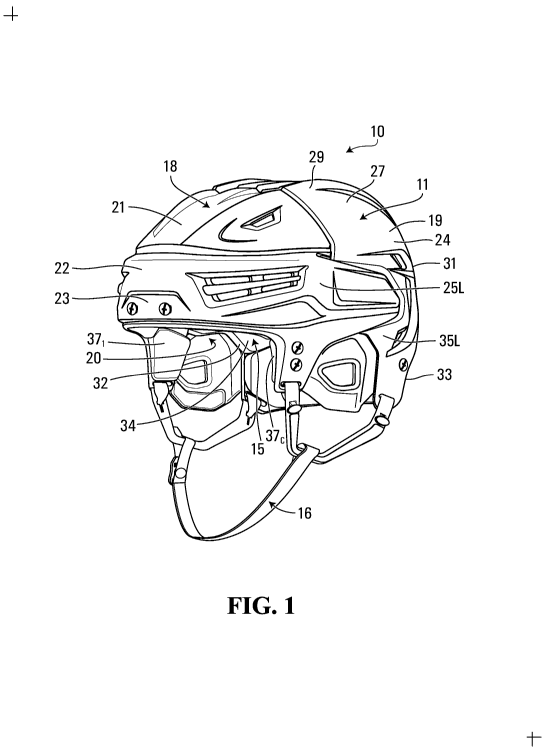
Figure 1 shows an example of a device 10 comprising a plurality of post-molded
expandable components 121-12E in accordance with an embodiment of the
invention. In
this embodiment, the device 10 is an article of athletic gear for a user
engaging in a
sport or other athletic activity. More particularly, in this embodiment, the
article of
athletic gear 10 is an article of protective athletic gear wearable by the
user to protect
him/her. Specifically, in this example, the article of protective athletic
gear 10 is a helmet
for protecting a head of the user against impacts. In this case, the helmet 10
is a hockey
helmet for protecting the head of the user, who is a hockey player, against
impacts
(e.g., from a puck or ball, a hockey stick, a board, ice or another playing
surface, etc.,
with another player, etc.).
Each of the post-molded expandable components 121-12E of the helmet 10 is a
part of
the helmet 10 that is configured to be expanded or has been expanded after
being
8
CA 03014381 2018-08-09
WO 2017/136941
PCT/CA2017/050154
molded (i.e., shaped in a mold). This may allow each of the post-molded
expandable
components 121-12E of the helmet 10 to have enhanced characteristics (e.g., be
more
shock-absorbent, lighter, etc.), to be cost-effectively manufactured (e.g., by
using less
material and/or making it in various sizes), and/or to be customized for the
user (e.g., by
custom-fitting it to the user in-store or at another location where it can be
expanded to
conform to the user).
In this embodiment, the helmet 10 comprises an outer shell 11 and an inner
liner 15 that
includes the post-molded expandable components 121-12E of the helmet 10. The
helmet
10 also comprises a chinstrap 16 for securing the helmet 10 to the player's
head. The
helmet 10 may also comprise a faceguard (not shown) to protect at least part
of the
player's face (e.g., a grid (sometimes referred to as a "cage") or a visor
(sometimes
referred to as a "shield")).
The helmet 10 defines a cavity 13 for receiving the player's head. In response
to an
impact, the helmet 10 absorbs energy from the impact to protect the player's
head. The
helmet 10 protects various regions of the player's head. As shown in Figures
47 and 48,
the player's head comprises a front region FR, a top region TR, left and right
side
regions LS, RS, a back region BR, and an occipital region OR. The front region
FR
includes a forehead and a front top part of the player's head and generally
corresponds
to a frontal bone region of the player's head. The left and right side regions
LS, RS are
approximately located above the player's ears. The back region BR is opposite
the front
region FR and includes a rear upper part of the player's head. The occipital
region OR
substantially corresponds to a region around and under the head's occipital
protuberance.
The helmet 10 comprises an external surface 18 and an internal surface 20 that
contacts the player's head when the helmet 10 is worn. The helmet 10 has a
front-back
axis FBA, a left-right axis LRA, and a vertical axis VA which are respectively
generally
parallel to a dorsoventral axis, a dextrosinistral axis, and a cephalocaudal
axis of the
player when the helmet 10 is worn and which respectively define a front-back
direction,
9
CA 03014381 2018-08-09
WO 2017/136941
PCT/CA2017/050154
a lateral direction, and a vertical direction of the helmet 10. Since they are
generally
oriented longitudinally and transversally of the helmet 10, the front-back
axis FBA and
the left-right axis LRA can also be referred to as a longitudinal axis and a
transversal
axis, respectively, while the front-back direction and the lateral direction
can also be
referred to a longitudinal direction and a transversal direction,
respectfully.
The outer shell 11 provides strength and rigidity to the helmet 10. To that
end, the outer
shell 11 comprises a rigid material 27. For example, in various embodiments,
the rigid
material 27 of the outer shell 11 may be a thermoplastic material such as
polyethylene
(PE), polyamide (nylon), or polycarbonate, a thermosetting resin, or any other
suitable
material. The outer shell 11 includes an inner surface 17 facing the inner
liner 15 and an
outer surface 19 opposite the inner surface 17. The outer surface 19 of the
outer shell
11 constitutes at least part of the external surface 18 of the helmet 10.
In this embodiment, the outer shell 11 comprises a front shell member 22 and a
rear
shell member 24 that are connected to one another. The front shell member 22
comprises a top portion 21 for facing at least part of the top region TR of
the player's
head, a front portion 23 for facing at least part of the front region FR of
the player's
head, and left and right lateral side portions 25L, 25R extending rearwardly
from the
front portion 23 for facing at least part of the left and right side regions
LS, RS of the
player's head, respectively. The rear shell member 24 comprises a top portion
29 for
facing at least part of the top region TR of the player's head, a back portion
31 for facing
at least part of the back region BR of the player's head, an occipital portion
33 for facing
at least part of the occipital region OR of the player's head, and left and
right lateral side
portions 35L, 35R extending forwardly from the back portion 31 for facing at
least part of
the left and right side regions LS, RS of the player's head, respectively.
In this embodiment, the helmet 10 is adjustable to adjust how it fits on the
player's head.
To that end, the helmet 10 comprises an adjustment mechanism 40 for adjusting
a fit of
the helmet 10 on the player's head. The adjustment mechanism 40 may allow the
fit of
the helmet 10 to be adjusted by adjusting one or more internal dimensions of
the cavity
CA 03014381 2018-08-09
WO 2017/136941
PCT/CA2017/050154
13 of the helmet 10, such as a front-back internal dimension FBD of the cavity
13 in the
front-back direction of the helmet 10 and/or a left-right internal dimension
LRD of the
cavity 13 in the left-right direction of the helmet 10, as shown in Figure 9.
More particularly, in this embodiment, the adjustment mechanism 40 is
configured such
that the outer shell 11 and the inner liner 15 are adjustable to adjust the
fit of the helmet
on the player's head. To that end, in this embodiment, the front shell member
22 and
the rear shell member 24 are movable relative to one another to adjust the fit
of the
helmet 10 on the player's head. In this example, relative movement of the
outer shell
10 members 22, 24 for adjustment purposes is in the front-back direction of
the helmet 10
such that the front-back internal dimension FBD of the cavity 13 of the helmet
10 is
adjusted. This is shown in Figures 5 to 8 in which the rear shell member 24 is
moved
relative to the front shell member 22 from a first position, which is shown in
Figure 5 and
which corresponds to a minimum size of the helmet 10, to a second position,
which is
shown in Figure 6 and which corresponds to an intermediate size of the helmet
10, and
to a third position, which is shown in Figures 7 and 8 and which corresponds
to a
maximum size of the helmet 10.
In this example of implementation, the adjustment mechanism 40 comprises an
actuator
41 that can be moved (in this case pivoted) by the player between a locked
position, in
which the actuator 41 engages a locking part 45 (as best shown in Figures 10
and 11)
of the front shell member 22 and thereby locks the outer shell members 22, 24
relative
to one another, and a release position, in which the actuator 41 is disengaged
from the
locking part 45 of the front shell member 22 and thereby permits the outer
shell
members 22, 24 to move relative to one another so as to adjust the size of the
helmet
10. The adjustment mechanism 40 may be implemented in any other suitably way
in
other embodiments.
The inner liner 15 is disposed between the outer shell 11 and the player's
head to
absorb impact energy when the helmet 10 is impacted. More particularly, the
inner liner
15 comprises a shock-absorbing structure 32 that includes an outer surface 38
facing
11
CA 03014381 2018-08-09
WO 2017/136941
PCT/CA2017/050154
towards the outer shell 11 and an inner surface 34 facing towards the player's
head. For
example, in some embodiments, the shock-absorbing structure 32 of the inner
liner 15
may comprise a shock-absorbing material. For instance, in some cases, the
shock-
absorbing material may include a polymeric cellular material, such as a
polymeric foam
(e.g., expanded polypropylene (EPP) foam, expanded polyethylene (EPE) foam, or
any
other suitable polymeric foam material), or expanded polymeric microspheres
(e.g.,
ExpancelTM microspheres commercialized by Akzo Nobel). Any other material with
suitable impact energy absorption may be used in other embodiments.
Additionally or
alternatively, in some embodiments, the shock-absorbing structure 32 of the
inner liner
.. 15 may comprise an array of shock absorbers that are configured to deform
when the
helmet 10 is impacted. For instance, in some cases, the array of shock
absorbers may
include an array of compressible cells that can compress when the helmet 10 is
impacted. Examples of this are described in U.S. Patent 7,677,538 and U.S.
Patent
Application Publication 2010/0258988, which are incorporated by reference
herein.
The inner liner 15 may be mounted to the outer shell 11 in any suitable way.
For
example, in some embodiments, the inner liner 15 may be mounted to the outer
shell 11
by one or more fasteners such as mechanical fasteners (e.g., tacks, staples,
rivets,
screws, stitches, etc.), an adhesive, or any other suitable fastener.
In this embodiment, the inner liner 15 comprises a plurality of pads 361-36A,
371-37c
disposed between the outer shell 11 and the player's head when the helmet 10
is worn.
In this example, respective ones of the pads 361-36A, 371-37c are movable
relative to
one another and with the outer shell members 22, 24 to allow adjustment of the
fit of the
helmet 10 using the adjustment mechanism 40.
The pads 361-36A are responsible for absorbing at least a bulk of the impact
energy
transmitted to the inner liner 15 when the helmet 10 is impacted and can
therefore be
referred to as "absorption" pads. In this embodiment, the pad 361 is for
facing at least
part of the front region FR and left side region LS of the player's head, the
pad 362 is for
facing at least part of the front region FR and right side region RS of the
player's head,
12
CA 03014381 2018-08-09
WO 2017/136941
PCT/CA2017/050154
the pad 363 is for facing at least part of the back region BR and left side
region LS of the
player's head, the pad 364 is for facing at least part of the back region BR
and right side
region RS of the player's head, and the pad 365 is for facing at least part of
the top
region TR and back region BR of the player's head. The front shell member 22
overlays
the pads 361, 362 while the rear shell member 24 overlays the pads 363, 364.
The pads 371-37c are responsible to provide comfort to the player's head and
can
therefore be referred to as "comfort" pads. The comfort pads 371-37c may
comprise any
suitable soft material providing comfort to the player. For example, in some
embodiments, the comfort pads 371-37c may comprise polymeric foam such as
polyvinyl chloride (PVC) foam, polyurethane foam (e.g., PORON XRD foam
commercialized by Rogers Corporation), vinyl nitrile foam or any other
suitable
polymeric foam material. In some embodiments, given ones of the comfort pads
371-37c
may be secured (e.g., adhered, fastened, etc.) to respective ones of the
absorption
pads 361-36A. In other embodiments, given ones of the comfort pads 361-36A may
be
mounted such that they are movable relative to the absorption pads 371-37c.
For
example, in some embodiments, one or more of the comfort pads 371-37c may be
part
of a floating liner as described in U.S. Patent Application Publication
2013/0025032,
which, for instance, may be implemented as the SUSPEND-TECHTm liner member
found in the BAUERTM RE-AKTTm and RE-AKT 100TM helmets made available by Bauer
Hockey, Inc.. The comfort pads 371-37c may assist in absorption of energy from
impacts, in particular, low-energy impacts.
The inner liner 15 comprises the post-molded expandable components 121-12E of
the
helmet 10. More particularly, in this embodiment, respective ones of the pads
361-36A
comprise respective ones of the post-molded expandable components 121-12E of
the
helmet 10. Specifically, in this example, each post-molded expandable
component 12
of the helmet 10 constitutes a pad 36x.
With additional reference to Figures 17 and 18, the post-molded expandable
component
12x of the helmet 10 constituting the pad 36x comprises an expandable material
50 that
13
CA 03014381 2018-08-09
WO 2017/136941
PCT/CA2017/050154
is molded into a precursor 12x* which can then be expanded by a stimulus
(e.g., heat or
another stimulus) to an expanded shape that is a scaled-up version of an
initial shape of
the precursor 12x*. Thus, in this example, a three-dimensional configuration
of the initial
shape of the precursor 12x* is such that, once the expandable material 50 is
expanded,
a three-dimensional configuration of the expanded shape of the post-molded
expandable component 12x imparts a three-dimensional configuration of the pad
36x
(e.g., including curved and/or angular parts of the pad 36x).
The post-molded expandable component 12x of the helmet 10 constituting the pad
36x is
"expandable" in that it is capable of expanding and/or has been expanded by a
substantial degree in response to a stimulus after being molded. That is, an
expansion
ratio of the post-molded expandable component 12x of the helmet 10
constituting the
pad 36x, which refers to a ratio of a volume of the post-molded expandable
component
12x of the helmet 10 after the expandable material 50 has been expanded
subsequently
to having been molded into the precursor 12x* over a volume of the precursor
12x* into
which the expandable material 50 is initially molded, may be significantly
high. For
example, in some embodiments, the expansion ratio of the post-molded
expandable
component 12x of the helmet 10 constituting the pad 36x may be at least 2, in
some
cases at least 3, in some cases at least 5, in some cases at least 10, in some
cases at
least 20, in some cases at least 30, in some cases at least 40 and in some
cases even
more (e.g., 45).
The expandable material 50 can be any material capable of expanding after
being
molded. In this embodiment, the expandable material 50 includes a mixture of a
polymeric substance 52 and an expansion agent 54 that allows the expandable
material
50 to expand. Once expanded into its final shape, the pad 36x may have
desirable
properties, such as being more shock-absorbent than it if had been made
entirely of the
expansion agent 54 and/or being lighter than if it had been made entirely of
the
polymeric substance 52.
14
CA 03014381 2018-08-09
WO 2017/136941
PCT/CA2017/050154
The polymeric substance 52 constitutes a substantial part of the expandable
material 50
and substantially contributes to structural integrity to the pad 36k. For
instance, in some
embodiments, the polymeric substance 52 may constitute at least 40%, in some
cases
at least 50%, in some cases at least 60%, in some cases at least 70%, in some
cases
at least 80%, and in some cases at least 90% of the expandable material 50 by
weight.
In this example of implementation, the polymeric substance 52 may constitute
between
50% and 90% of the expandable material 50 by weight.
In this embodiment, the polymeric substance 52 may be an elastomeric
substance. For
instance, the polymeric substance 52 may be a thermoplastic elastomer (TPE) or
a
thermoset elastomer (TSE).
More particularly, in this embodiment, the polymeric substance 52 comprises
polyurethane. The polyurethane 52 may be composed of any suitable constituents
such
as isocyanates and polyols and possibly additives. For instance, in some
embodiments,
the polyurethane 52 may have a hardness in a scale of Shore 00, Shore A, Shore
C or
Shore D, or equivalent. For example, in some embodiments, the hardness of the
polyurethane 52 may be between Shore 5A and 95A or between Shore D 40D to 93D.
Any other suitable polyurethane may be used in other embodiments.
The polymeric substance 52 may comprise any other suitable polymer in other
embodiments. For example, in some embodiments, the polymeric substance 52 may
comprise silicon, rubber, etc.
The expansion agent 54 is combined with the polyurethane 52 to enable
expansion of
the expandable material 50 to its final shape after it has been molded. A
quantity of the
expansion agent 54 allows the expandable material 50 to expand by a
substantial
degree after being molded. For instance, in some embodiments, the expansion
agent
54 may constitute at least 10%, in some cases at least 20%, in some cases at
least
30%, in some cases at least 40%, in some cases at least 50%, and in some cases
at
least 60%, of the expandable material 50 by weight and in some cases even
more. In
CA 03014381 2018-08-09
WO 2017/136941
PCT/CA2017/050154
this example of implementation, the expansion agent 54 may constitute between
15%
and 50% of the expandable material 50 by weight. Controlling the quantity of
the
expansion agent 54 may allow control of the expansion ratio of the post-molded
expandable component 12x
In this embodiment, as shown in Figure 19, the expansion agent 54 comprises an
amount of expandable microspheres 601-60m. Each expandable microsphere 60;
comprises a polymeric shell 62 expandable by a fluid encapsulated in an
interior of the
polymeric shell 62. In this example of implementation, the polymeric shell 62
of the
expandable microsphere 60; is a thermoplastic shell. The fluid encapsulated in
the
polymeric shell 62 is a liquid or gas (in this case a gas) able to expand the
expandable
microsphere 60; when heated during manufacturing of the pad 36x. In some
embodiments, the expandable microspheres 601-60m may be ExpancelTM
microspheres
commercialized by Akzo Nobel. In other embodiments, the expandable
microspheres
601-60m may be Dualite microspheres commercialized by Henkel; AdvanceII
microspheres commercialized by Sekisui; Matsumoto Microsphere microspheres
commercialized by Matsumoto Yushi Seiyaku Co; or KUREHA Microsphere
microspheres commercialized by Kureha. Various other types of expandable
microspheres may be used in other embodiments.
In this example of implementation, the expandable microspheres 601-60m include
dry
unexpanded (DU) microspheres when combined with the polymeric substance 52 to
create the expandable material 50 before the expandable material 50 is molded
and
subsequently expanded. For instance, the dry unexpanded (DU) microspheres may
be
provided as a powder mixed with one or more liquid constituents of the
polymeric
substance 52.
The expandable microspheres 601-60m may be provided in various other forms in
other
embodiments. For example, in some embodiments, the expandable microspheres 60i-
60m may include dry expanded, wet and/or partially-expanded microspheres. For
instance, wet unexpanded microspheres may be used to get better bonding with
the
16
CA 03014381 2018-08-09
WO 2017/136941
PCT/CA2017/050154
polymeric substance 52. Partially-expanded microspheres may be used to employ
less
of the polymeric substance 52, mix with the polymeric substance 52 in semi-
solid form,
or reduce energy to be subsequently provided for expansion.
In some embodiments, the expandable microspheres 601-60m may constitute at
least
10%, in some cases at least 20%, in some cases at least 30%, in some cases at
least
40%, in some cases at least 50%, and in some cases at least 60 /0of the
expandable
material 50 by weight and in some cases even more. In this example of
implementation,
the expandable microspheres 601-60m may constitute between 15% and 50% of the
io expandable material 50 by weight.
The post-molded expandable component 12x of the helmet 10 constituting the pad
36x
may have various desirable qualities.
For instance, in some embodiments, the pad 36x may be less dense and thus
lighter
than if it was entirely made of the polyurethane 52, yet be more shock-
absorbent and/or
have other better mechanical properties than if it was entirely made of the
expandable
microspheres 601-60m.
For example, in some embodiments, a density of the expandable material 50 of
the pad
36x may be less than a density of the polyurethane 52 (alone). For instance,
the density
of the expandable material 50 of the pad 36x may be no more than 70%, in some
cases
no more than 60%, in some cases no more than 50%, in some cases no more than
40%, in some cases no more than 30%, in some cases no more than 20%, in some
cases no more than 10%, and in some cases no more than 5% of the density of
the
polyurethane 52 and in some cases even less. For example, in some embodiments,
the
density of the expandable material 50 of the pad 36x may be between 2 to 75
times less
than the density of the polyurethane 52 ,i.e., the density of the expandable
material 50
of the pad 36x may be about 1% to 50% of the density of the polyurethane 52).
17
CA 03014381 2018-08-09
WO 2017/136941
PCT/CA2017/050154
The density of the expandable material 50 of the pad 36x may have any suitable
value.
For instance, in some embodiments, the density of the expandable material 50
of the
pad 36x may be no more than 0.7 g/cm3, in some cases no more than 0.4 g/cm3 ,
in
some cases no more than 0.1 g/cm3, in some cases no more than 0.080 g/cm3, in
some
cases no more than 0.050 g/cm3, in some cases no more than 0.030 g/cm3, and/or
may
be at least 0.010 g/cm3. In some examples of implementation, the density of
the
expandable material 50 may be between 0.015 g/cm3 and 0.080 g/cm3, in some
cases
between 0.030 g/cm3 and 0.070 g/cm3, and in some cases between 0.040 g/cm3 and
0.060 g/cm3.
As another example, in some embodiments, a stiffness of the expandable
material 50 of
the pad 36x may be different from (i.e., greater or less than) a stiffness of
the
expandable microspheres 601-60m (alone). For instance, a modulus of elasticity
(i.e.,
Young's modulus) of the expandable material 50 of the pad 36x may be greater
or less
than a modulus of elasticity of the expandable microspheres 601-60m (alone).
For
instance, a difference between the modulus of elasticity of the expandable
material 50
of the pad 36x and the modulus of elasticity of the expandable microspheres
601-60m
may be at least 20%, in some cases at least 30%, in some cases at least 50%,
and in
some cases even more, measured based on a smaller one of the modulus of
elasticity
of the expandable material 50 of the pad 36x and the modulus of elasticity of
the
expandable microspheres 601-60m. In some cases, the modulus of elasticity may
be
evaluated according to ASTM D-638 or ASTM D-412.
As another example, in some embodiments, a resilience of the expandable
material 50
of the pad 36x may be less than a resilience of the expandable microspheres
601-60m
(alone). For instance, in some embodiments, the resilience of the expandable
material
50 of the pad 36x may be no more than 70%, in some cases no more than 60%, in
some cases no more than 50%, in some cases no more than 40%, in some cases no
more than 30%, in some cases no more than 20%, and in some cases no more than
10% of the resilience of the expandable microspheres 601-60m according to ASTM
D2632-01 which measures resilience by vertical rebound. In some examples of
18
CA 03014381 2018-08-09
WO 2017/136941
PCT/CA2017/050154
implementation, the resilience of the expandable material 50 of the pad 36x
may be
between 20% and 60% of the resilience of the expandable microspheres 601-60m.
Alternatively, in other embodiments, the resilience of the expandable material
50 of the
pad 36x may be greater than the resilience of the expandable microspheres 601-
60m.
The resilience of the expandable material 50 of the pad 36x may have any
suitable
value. For instance, in some embodiments, the resilience of the expandable
material 50
of the pad 36x may be no more than 40%, in some cases no more than 30%, in
some
cases no more than 20%, in some cases no more than 10% and in some cases even
less (e.g., 5%), according to ASTM D2632-01, thereby making the pad 36x more
shock-
absorbent. In other embodiments, the resilience of the expandable material 50
of the
pad 36x may be at least 60%, in some cases at least 70%, in some cases at
least 80%
and in some cases even more, according to ASTM D2632-01, thereby making the
expandable material 50 provide more rebound (e.g., which may be useful in
other
embodiments where the post-molded expandable component 12x is part of other
devices, as discussed later).
As another example, in some embodiments, a tensile strength of the expandable
material 50 of the pad 36x may be greater than a tensile strength of the
expandable
microspheres 601-60m (alone). For instance, in some embodiments, the tensile
strength
of the expandable material 50 of the pad 36x may be at least 120%, in some
cases at
least 150%, in some cases at least 200%, in some cases at least 300%, in some
cases
at least 400%, and in some cases at least 500% of the tensile strength of the
expandable microspheres 601-60m according to ASTM D-638 or ASTM D-412, and in
some cases even more.
The tensile strength of the expandable material 50 of the pad 36x may have any
suitable
value. For instance, in some embodiments, the tensile strength of the
expandable
material 50 of the pad 36x may be at least 0.9 MPa, in some cases at least 1
MPa, in
some cases at least 1.2 MPa, in some cases at least 1.5 MPa and in some cases
even
more (e.g. 2 MPa or more).
19
CA 03014381 2018-08-09
WO 2017/136941
PCT/CA2017/050154
As another example, in some embodiments, an elongation at break of the
expandable
material 50 of the pad 36x may be greater than an elongation at break of the
expandable microspheres 601-60m (alone). For instance, in some embodiments,
the
elongation at break of the expandable material 50 of the pad 36x may be at
least 120%,
in some cases at least 150%, in some cases at least 200%, in some cases at
least
300%, in some cases at least 400%, and in some cases at least 500% of the
elongation
at break of the expandable microspheres 601-60m according to ASTM D-638 or
ASTM
D-412, and in some cases even more.
The elongation at break of the expandable material 50 of the pad 36x may have
any
suitable value. For instance, in some embodiments, the elongation at break of
the
expandable material 50 of the pad 36x may be at least 20%, in some cases at
least
30%, in some cases at least 50%, in some cases at least 75%, in some cases at
least
100%, and in some cases even more (e.g. 150% or more).
With additional reference to Figure 20, in this embodiment, the post-molded
expandable
component 12x constituting the pad 36x of the helmet 10 may be manufactured
by:
providing the expandable material 50; molding the expandable material 50 into
the
precursor 12x* in a mold 70; and expanding the expandable material 50 to the
expanded
shape which is the scaled-up version of the initial shape of the precursor
12x* and which
corresponds to the three-dimensional configuration of the post-molded
expandable
component 12x, by subjecting the precursor 12x* made of the expanded material
50 to a
stimulus (e.g., heat) after the precursor 12x* has been molded (e.g., outside
of the mold
70). That is, expansion of the precursor 12x* made of the expanded material 50
to the
expanded shape of the post-molded expandable component 12x is caused by energy
transmitted to the precursor 12x* made of the expanded material 50 after the
precursor
12x* has been molded (e.g., outside of the mold 70).
CA 03014381 2018-08-09
WO 2017/136941
PCT/CA2017/050154
The expandable material 50 may be provided in any suitable way and any
suitable
molding process using the mold 70 may be used to mold the expandable material
50
into the precursor 12x*.
In this embodiment, the expandable material 50 is provided as a fluid flowing
into the
mold 70 to undergo the molding process to mold the expandable material 50 into
the
precursor 12x*. In particular, in order to obtain the expandable material 50,
the
expandable microspheres 601-60m are combined with the polyurethane 52. For
instance, the expandable microspheres 601-60m may be introduced into one or
more
components of the polyurethane 52 prior to mixing of the components of the
polyurethane 52 (e.g., isocyanates and/or polyols). For example, in this
embodiment,
the expandable microspheres 601-60m are introduced into the isocyanates of the
polyurethane 52 prior to mixing the isocyanates, the polyols and any other
components
of the polyurethane 52 if any. This may allow the isocyanates to react to the
moisture
present in the expandable microspheres 601-60m. The expandable microspheres
60i-
60m may be introduced into the polyols of the polyurethane 52 in other
embodiments.
Moreover, in this example, the expandable microspheres 601-60m are introduced
into
the polyurethane 52 as dry unexpanded microspheres.
Also, in this embodiment, the molding process of the precursor 12x* is a low-
temperature molding process during which a temperature of the expandable
material 50
being molded is lower than an expansion temperature at which the expandable
microspheres 601-60m are expanded. For instance, in some embodiments where the
expansion temperature of the expandable microspheres 601-60m may be 70 C or
more,
the molding process may be carried out such that the temperature of the
expandable
material 50 being molded is less than 70 C (e.g., 40 C).
In this example, the molding process of the precursor 12x* is also done at low
pressure
such that it is a low-temperature and low-pressure molding process. This may
be done
since expansion of the expandable material 50 occurs after it has been molded
(e.g.,
outside of the mold 70).
21
CA 03014381 2018-08-09
WO 2017/136941
PCT/CA2017/050154
More particularly, in this embodiment, the molding process of the precursor
12x* is
injection molding. For instance, in this embodiment, the molding process is
carried out
via a molding apparatus 75 comprising the mold 70. In this example, the
molding
process includes feeding the expandable material 50 into a barrel of the
molding
apparatus 75 (e.g., via a hopper) in which a mechanism (e.g., a screw
mechanism)
causes displacement of the expandable material 50 towards a sprue of the mold
70.
Once the expandable material 50 reaches the sprue of the mold 70, the
expandable
material 50 is injected into a mold cavity 72 of the mold 70 that is shaped
like the
precursor 12x*. After the expandable material 50 has shaped into it, the
precursor 12x*
is removed from the mold 70. One or more finishing operations may be carried
out in
order to produce the finished precursor 12x* (e.g., deflashing).
In some cases, the molding process of the precursor 12x* may use one or more
inserts
.. (e.g., cores) which are disposed within the mold 70 prior to forming the
precursor 12x*
and which are configured to form empty spaces within the precursor 12x* (e.g.,
vents).
Such inserts may comprise a material having a low melting temperature. For
example,
the material of the inserts may comprise wax, expanded polyethylene (EPE),
expanded
polystyrene (EPS), or any other suitable material.
Since in this embodiment the molding process is a low-temperature and low-
pressure
injection molding process, production of the mold 70 may be less expensive and
safer
than if a high-temperature and/or high-pressure injection molding process was
implemented. Moreover, this may result in an overall lowered stress condition
in the
precursor 12x*.
The mold 70 in which the expandable material 50 is molded may be provided in
any
suitable way in various embodiments.
For example, in this embodiment, the mold 70 may be created by additive
manufacturing, a.k.a., 3D printing, such as selective laser sintering (SLS),
22
CA 03014381 2018-08-09
WO 2017/136941
PCT/CA2017/050154
stereolithography (SLA), etc. This may be facilitated since the mold 70 may be
relatively
small, given that the expandable material 50 will be expanded after being
molded in the
mold 70.
More particularly, in this embodiment, as shown in Figure 21, the mold 70 is
made by a
3D printer 76. The 3D printer 76 is configured to form a three-dimensional
object based
at least in part on a design file (e.g., a CAD file) that is generated on a
computing
apparatus (e.g., a desktop computer, a laptop, a tablet, a smartphone, etc.).
To that
end, the 3D printer 76 deposits layers of material on top of one another in
order to form
.. the three-dimensional object. For instance, the 3D printer 76 may generally
include a
printer head (e.g., an extruder) that is movable along two or more axes (e.g.,
an x-axis
and a z-axis) and a printer bed that may be stationary or movable along one or
more
axes (e.g., a y-axis). The 3D printer 76 may be configured in various other
ways in other
embodiments (e.g., having components movable along a polar coordinate system).
Thus, in this embodiment, the mold 70 comprises a printed material 74 that is
layered
by the 3D printer 76 in order to form the mold 70. In this embodiment, the
printed
material 74 of the mold 70 is a polymeric material, and more specifically, a
polyurethane
material. The printed material 74 of the mold 70 may comprise any other
suitable
polymeric material in other embodiments (e.g., silicon, polycarbonate, etc.).
Moreover,
in some embodiments, the printed material 74 of the mold 70 may comprise a
metallic
material or a ceramic material.
In embodiments where the mold 70 is made via SLS, a material of the mold 70
may
comprise a powdered material. For example, the material of the mold 70 may
comprise
a metallic powdered material or a polymeric powdered material. Alternatively,
in
embodiments where the mold 70 is made via SLA, the material of the mold 70 may
comprise a polymeric resin.
Making the mold 70 via the 3D printer 76 (i.e., via additive manufacturing)
may
decrease a cost of making the mold 70 (e.g., by reducing the amount of time
needed to
23
CA 03014381 2018-08-09
WO 2017/136941
PCT/CA2017/050154
manufacture the mold 70) and therefore lead to a decrease in a production cost
of the
post-molded expandable component 12x. Moreover, using the 3D printer 76 to
make the
mold 70 may facilitate producing custom designs of the post-molded expandable
component 12x.
The mold 70 may be configured in any suitable way. For instance, an example of
configuration of the mold 70 is shown in Figure 39. In this example, the mold
70
comprises first and second mold halves 711, 712 which are complimentary to one
another. For example, the first mold half 711 may comprise a plurality of
first connectors
731-73c (e.g., protrusions, ridges, etc.) that are configured to fit a
plurality of second
connectors 771-77c (e.g., recesses, holes, etc.) of the second mold half 712
to correctly
position the first mold half 711 relative to the second mold half 712 and to
secure the two
mold halves 711, 712 together. The mold 70 may also comprise a sealing member
78
(e.g., a gasket) to prevent or otherwise minimize loss of the material to be
molded in the
mold 70 during molding. The mold cavity 72 of the mold 70 is formed when the
first and
second mold halves 711, 712 are secured to one another. In this example, the
material
of the mold 70 comprises silicone. The material of the mold 70 may comprise
any other
suitable material in other examples.
The mold 70 in which the expandable material 50 is molded may be made in any
other
suitable manner in other embodiments.
For instance, in some embodiments, the mold 70 may be thermoformed. An example
of
the mold 70 that is thermoformed is shown in Figures 40 and 41. In this
example, each
of the first and second mold halves 711, 712 of the mold 70 consists of a
thermoformed
sheet comprising a thermoformable material. That is, each of the first and
second mold
halves 711, 712 is originally a sheet of thermoformable material that is
heated and
subsequently deformed to acquire its final shape. As shown in Figures 42A and
42B, a
compression device 79 may be provided when molding the precursor 12x* with the
thermoformed mold 70 in order to compress the sealing member 78 during molding
(e.g., injection molding). The compression device 79 may comprise first and
second
24
CA 03014381 2018-08-09
WO 2017/136941
PCT/CA2017/050154
members 811, 812 being disposed on top and below the mold 70 such as to
sandwich
the first and second mold halves 711, 712 at a peripheral portion of the first
and second
mold halves 711, 712. An opening may be provided on one or both members 811,
812 of
the compression device 79 to allow a certain amount of deformation of the mold
70 at a
location of the mold cavity 72.
As the expandable material 50 molded into the precursor 12x* will be
subsequently
expanded, in this embodiment, the mold 70 may effectively be used to
manufacture
post-molded expandable components like the post-molded expandable component 1
2x
that have different sizes (i.e., by controlling expansion of the expandable
material 50
after it has been molded).
For example, in this embodiment, with additional reference to Figure 22, the
mold 70 is
used to produce the precursor 12x* which may be expanded into a post-molded
expandable component of a first size 12x1 (e.g., a small size), a post-molded
expandable component of a second size 12x2 (e.g., a medium size), or a post-
molded
expandable component of a third size 12x3 (e.g., a large size). The precursor
12x* may
be expanded into more sizes in other embodiments (e.g., a junior size, an
extra-large
size). As such, a single mold 70 may allow manufacturing post-molded
expandable
components 121-12E of various sizes.
Upon having been molded into the precursor 12x* in the mold 70, the expandable
material 50 is subsequently subjected to a stimulus which causes it to expand
into its
expanded shape that is the scaled-up version of the initial shape of the
precursor 12x*
and that corresponds to the three-dimensional configuration of the post-molded
expandable component 12x constituting the pad 36x of the helmet 10.
In this embodiment, there may be a substantial amount of time after molding of
the
expandable material 50 into the precursor 12x* in the mold 70 and before
expansion of
the expandable material 50 into its expanded shape that is the scaled-up
version of the
initial shape of the precursor 12x* and that corresponds to the three-
dimensional
CA 03014381 2018-08-09
WO 2017/136941
PCT/CA2017/050154
configuration of the pad 36,, which will be referred to as a substantial "post-
molding pre-
expansion amount of time". The stimulus causing expansion of the expandable
material
50 may thus be initiated after the substantial post-molding pre-expansion
amount of
time following molding of the precursor 12,* in the mold 70.
The substantial post-molding pre-expansion amount of time may allow the
properties of
the expandable material 50 in its expanded shape to be enhanced, including its
stiffness, resilience, and tensile strength, as discussed above. More
particularly, during
the substantial post-molding pre-expansion amount of time, the expandable
material 50
of the precursor 12,* may undergo a chemical reaction (e.g., polymerization)
or other
reaction that can enhance its properties, such as its stiffness, resilience,
and tensile
strength, compared to if it had been instantly or rapidly expanded upon being
molded in
the mold 70.
For example, in some embodiments, the substantial post-molding pre-expansion
amount of time for the expandable material 50 of the precursor 12,* may be at
least one
hour, in some cases at least ten hours, in some cases at least one day, in
some cases
at least two days, in some cases at least three days, in some cases at least
five days, in
some cases at least seven days, and in some cases even more.
In this embodiment, expansion of the expandable material 50 of the precursor
12,* into
the three-dimensional configuration of the pad 36, in response to the stimulus
occurs
outside of the mold 70 in which the precursor 12,*. That is, upon having been
molded
into the precursor 12,* in the mold 70, the expandable material 50 is removed
from the
mold 70 and then subjected to the stimulus which causes it to expand.
The stimulus causing expansion of the expandable material 50 is energy
transmitted to
the expandable material 50 causing its expansion. In this embodiment, heat is
the
stimulus causing expansion of the expandable material 50. More particularly,
in this
embodiment, the expandable material 50 is subjected to heat generated by a
heat
source 80 which causes the expandable material 50 of the precursor 12,* to
expand into
26
CA 03014381 2018-08-09
WO 2017/136941
PCT/CA2017/050154
the post-molded expandable component 12x. In this embodiment, as shown in
Figure
23, the heat source 80 comprises an oven 82 comprising a thermally-insulated
chamber
and at least one heating element disposed within the thermally insulated
chamber. In
this example, the oven 82 is powered electrically, however the oven 82 may be
powered
in any suitable way in other examples (e.g., a gas-powered oven). Moreover,
the oven
82 may be any suitable type of oven such as, for example, an industrial oven,
a
conventional oven, or a microwave oven. In other embodiments, the heat source
80
may be a hot liquid (e.g., the precursor 12x* may be subject to a hot liquid
bath) or a hot
gas (e.g., hot air expulsed by a blower).
The oven 82 is configured to generate heat such as to attain and maintain a
given
temperature within its insulated chamber. In this example, the given
temperature is set
by a user of the oven 82 (e.g., via a control) to cause the precursor 12x* to
be heated
such that the expandable material 50 reaches its expansion temperature at
which the
expandable microspheres 601-60m of the expandable material 50 expand. The
expansion temperature of the expandable material 50, and thus of the precursor
may vary. For instance, in some cases, the expansion temperature of the
precursor 12x*
may be at least 70 C, in some cases at least 90 C, in some cases at least 110
C, in
some cases at least 130 C, in some cases at least 150 C and in some cases even
more (e.g., 160 C).
In order to cause the expandable material 50 of the precursor 12x* to expand
to its
expanded shape corresponding to the three-dimensional configuration of the pad
36k,
the expansion temperature of the precursor 12x* is held for a given amount of
time. The
given amount of time may be referred to as an "expansion time" of the
precursor 12x*
since it is the time it takes for the expandable material 50 of the precursor
12x* to
expand into the post-molded expandable component 12x. The expansion time of
the
precursor 12x* may vary. For instance, in some cases, the expansion time of
the
precursor may be at least 10 seconds, in some cases at least 1 minute, in some
cases
at least 5 minutes, in some case at least 10 minutes, in some cases at least
20 minutes,
27
CA 03014381 2018-08-09
WO 2017/136941
PCT/CA2017/050154
in some cases at least 30 minutes, in some cases at least 40 minutes, and in
some
cases even more (e.g., 60 minutes).
By controlling the expansion temperature, the expansion time and the quantity
of the
expandable microspheres 601-60m of the precursor 12x*, an operator of the oven
82 is
able to control the expansion ratio of the post-molded expandable component
12x and
thus the size of the post-molded expandable component 12x constituting the pad
36x. In
other words, by controlling the expansion temperature, the expansion time and
the
quantity of the expandable microspheres 601-60m of the precursor 12x*, the
operator
can produce the post-molded expandable component 12x constituting the pad 36x
in
accordance to various sizes (e.g., small, medium, large sizes).
Expansion of the expandable material 50 into the post-molded expandable
component
12x of the helmet 10 constituting the pad 36x may be performed by any suitable
entity.
In this embodiment, expansion of the expandable material 50 into the post-
molded
expandable component 12x of the helmet 10 constituting the pad 36x may be
performed
by a manufacturer of the helmet 10 during original manufacturing of the helmet
10. For
instance, the manufacturer of the helmet 10 may use the molding apparatus 75
and the
mold 70 as described above to make the precursor 12x* and thereafter subject
the
precursor 12x* to heat generated by the heat source 80 (e.g., the oven 82) in
order to
cause the expandable material 50 of the precursor 12x* to expand to form the
post-
molded expandable component 12x. As such, in this embodiment, the manufacturer
of
the helmet 10 is able to make different sizes of the pad 36x for different
sizes of the
helmet 10 by using the mold 70.
The post-molded expandable component 12x of the helmet 10 constituting the pad
36x
may be implemented in any other suitable way in other embodiments.
For instance, in some embodiments, as shown in Figure 43, the expandable
material 50
of the post-molded expandable component 12x may be one of a plurality of
expandable
28
CA 03014381 2018-08-09
WO 2017/136941
PCT/CA2017/050154
materials 1501-150E of the post-molded expandable component 12x that have
different
properties from one another.
For example, in some cases, a given expandable material 150; of the post-
molded
expandable component 12x may have a greater expansion ratio than another
expandable material 150k of the post-molded expandable component 12x. As such
the
given expandable material 150; may expand more than the other expandable
material
150k when subjected to a similar stimulus.
In some examples, a given expandable material 150; of the post-molded
expandable
component 12x may have a different stiffness, hardness or density than another
expandable material 150k. This may impart different mechanical properties at
different
regions of the post-molded expandable component 150k. For instance, an
expandable
material 150; that is more outwardly disposed than another expandable material
150k
(i.e., being more spaced apart from the player's head at a portion or an
entirety of the
post-molded expandable component 12x) may have a greater stiffness than the
other
expandable material 150k For example, the expandable material 150; that is
more
outwardly disposed than the other expandable material 150k may have a greater
stiffness to protect the player's head from an impact while the other
expandable material
150k that is more inwardly disposed may have a smaller stiffness so as to be
more
comfortable on the player's head.
The plurality of expandable materials 1501-150E of the post-molded expandable
component 12x may be formed via a multi-injection molding process in which the
plurality of expandable materials 1501-150E are molded subsequently using a
same
molding apparatus. This may be done by loading two or more different feeders
of the
molding apparatus with the expandable materials 1501-150E in order to inject
the
expandable materials 1501-150E into each mold cavity of a mold. The mold is
movable
within the molding apparatus (e.g., rotatable) to bring each mold cavity into
its "fill
position" for each expandable material 150. A similar multi-part casting
process may be
performed to form the plurality of expandable materials 1501-150E.
29
CA 03014381 2018-08-09
WO 2017/136941
PCT/CA2017/050154
As another example, in some embodiments, as shown in Figure 45, the pad 36x
may
comprise a decorative outer layer 81 constituting at least part of an outer
surface 88 of
the pad 36x. The decorative outer layer 81 is colored differently than (i.e.,
includes one
or more colors different from that of) the expandable material 50 of the pad
36x. In some
examples, the decorative outer layer 81 may include a graphical representation
of: one
or more alphanumeric characters that may form text (e.g., a word, a message,
etc.); one
or more symbols (e.g., a logo, a sign, an emblem, etc.); one or more shapes or
patterns;
and/or one or more real or imaginary objects (e.g., a person, an animal, a
vehicle, an
imaginary or fictional character, or any other real or imaginary thing).
The decorative outer layer 81 may be implemented in any suitable way. For
instance, in
some embodiments, the decorative outer layer 81 may comprise: a coating, such
as a
dye, paint (e.g., applied by spraying, dipping, etc.); a print (e.g., a direct
printing, a pad
printing, sublimation); a laser engraving; a sheet, such as a film; etc., or
any
combination thereof.
In some embodiments, the decorative outer layer 81 may be part of the pad 36x
before
expansion of the expandable material 50 of the pad 36x, such that the
decorative outer
layer 81 expands with the expandable material 50 when subjected to the
stimulus (e.g.,
heat) after molding. For example, in some embodiments, the expandable material
50
and the decorative outer layer 81 may be implemented by different expandable
materials 1501-150E as discussed above. In some cases, the decorative outer
layer 81
may be applied onto an internal surface of the mold 70 so as to form the outer
surface
88 of the precursor 12x* during molding.
In other embodiments, the decorative outer layer 81 may be provided after
expansion of
the expandable material 50 of the pad 36x. For instance, in some examples, the
decorative outer layer 81 may be affixed (e.g., adhesively or chemically
bonded) to the
expandable material 50 after the expandable material 50 has been expanded.
CA 03014381 2018-08-09
WO 2017/136941
PCT/CA2017/050154
Alternatively or additionally, in some embodiments, the outer surface 88 of
the pad 36x
may comprise a molded texture 89 imparted during molding of the precursor
12x*, i.e.,
during molding of the expandable material 50 or an outer one of the expandable
materials 1501-150E, where applicable. The molded texture 89 comprises a
predetermined arrangement of relief elements 911-915 (i.e., one or more
recesses
and/or one or more projections) of the outer surface 88 of the pad 36x. The
relief
elements 911-915 are present in the precursor 12x* as they are created by the
mold 70
and then expanded during expansion of the expandable material 50 or the outer
one of
the expandable materials 1501-150E, where applicable.
As another example, in a variant, with additional reference to Figure 24, the
molding
process of the precursor 12x* may be casting. The casting process of the
precursor 12x*
involves molding the expandable material 50 in a mold 90 configured to produce
the
precursor 12x*. More specifically, the casting process involves pouring the
expandable
material 50, in a fluid state, into the mold 90 via a sprue thereof in order
to fill a mold
cavity 92 of the mold 90 that has the shape of the precursor 12x*. Once the
expandable
material 50 has cured within the mold cavity 92, the precursor 12x* is formed
and can be
removed from the mold 90. Additional finishing processes may be carried out on
the
precursor 12x* (e.g., deflashing).
While Figure 24 illustrates the mold 90 configured in a certain way, the mold
90 may be
configured in any suitable way in other embodiments. For instance, the mold 90
may
comprise additional features (e.g., a pouring cup, runners, gates, etc.).
In another variant, the molding process of the precursor 12x* may be
thermoforming.
For instance, the expandable material 50 may be provided as a thermoformable
sheet
94 that is thermoformed in order to produce the precursor 12x* from which the
post-
molded expandable component 12x may be formed by expansion.
In this example, with additional reference to Figures 25A and 25B, an
extrusion
mechanism 96 (e.g., a sheet extruder) is used to produce the thermoformable
sheet 94.
31
CA 03014381 2018-08-09
WO 2017/136941
PCT/CA2017/050154
More specifically, the expandable material 50 is fed into the extrusion
mechanism 96
(e.g., via a hopper) and circulated through a barrel of the extrusion
mechanism 96. In
some cases, the barrel may be heated to soften or liquefy the expandable
material 50 in
order to facilitate its deformation as it is manipulated by the extrusion
mechanism 96.
The expandable material 50 is then fed into a die of the extrusion mechanism
96 that
forms the expandable material 50 into a sheet which is subsequently passed
between a
pair of rollers of the extrusion mechanism 96 in order to reduce a thickness
of the sheet.
In some embodiments, as shown in Figure 25B, the sheet thickness may instead
be
reduced by passing the sheet through a scraper of the extrusion mechanism 96
(e.g.,
io supported on a conveyor mechanism). The extrusion mechanism 96 may also
comprise
a cutting subassembly (e.g., a slitter, a guillotine, etc.) for partitioning
the extruded sheet
into multiple thermoformable sheets 94 of a desired size. The extrusion
process may be
performed below the expansion temperature of the expandable material 50.
The extrusion mechanism 96 may be configured in any other suitable way. For
instance,
the extrusion mechanism 96 may comprise additional components (e.g., a breaker
plate) that are not shown. Moreover, the thermoformable sheet 94 may be formed
in
any other suitable way in other examples.
With additional reference to Figures 26 and 27, the thermoforming process of
the
precursor 12x* is performed using a molding apparatus 100. In this example,
the
molding apparatus 100 comprises a negative mold 102 and a positive mold 104
that is
shaped complementarily to the negative mold 102. As shown in Figure 26, in
order to
begin the thermoforming process, the thermoformable sheet 94 is heated and
placed on
top of the negative mold 102. As shown in Figure 27, the positive mold 104 is
then
pressed onto the negative mold 102 such as to sandwich the thermoformable
sheet 94
between the positive mold 104 and the negative mold 102, thus causing the
thermoformable sheet 94 to acquire the shape of the negative and positive
molds 102,
104. Once the thermoformable sheet 94 has cured, the positive mold 104 is
disengaged
from the negative mold 102 and the formed precursor 12x* is removed therefrom.
32
CA 03014381 2018-08-09
WO 2017/136941
PCT/CA2017/050154
Additional finishing processes may be carried out on the precursor 12x* (e.g.,
deflashing).
The molding apparatus 100 may be configured in any other suitable way. For
instance,
in some examples, the thermoforming process may be a vacuum thermoforming
process or any other suitable thermoforming process,
In a variant, in some embodiments, the stimulus for expanding the expandable
material
50 may be any other suitable stimulus (e.g., microwave, ultraviolet (UV)
light, etc.).
For instance, with additional reference to Figure 44, in one example, the
expandable
material 50 of the post-molded expandable component 12x may be caused to
expand by
infrared light. That is, subjecting the expandable material 50 of the post-
molded
expandable component 12x to infrared light IR of a given intensity for a given
exposure
time may cause the post-molded expandable component 12x to expand. Thus by
controlling the intensity and exposure time of the infrared light IR on the
post-molded
expandable component 12x, one may control the expansion of the expandable
material
50 of the post-molded expandable component 12x. As another example, the
expandable
material 50 of the post-molded expandable component 12x may be caused to
expand by
ultrasonic vibrations. For instance, subjecting the expandable material 50 of
the post-
molded expandable component 12x to ultrasonic vibrations may cause molecules
of the
expandable material 50 to vibrate and thus generate heat. Thus, by controlling
the
intensity of the ultrasonic vibrations and an amount of time to which the
expandable
material 50 is subjected to the ultrasonic vibrations, one may control the
expansion of
the expandable material 50 of the post-molded expandable component 12x.
In a variant, in some embodiments, the expansion of the expandable material 50
into
the post-molded expandable component 12x of the helmet 10 constituting the pad
36x
may be performed by a retailer or other entity selling the helmet 10 to buyers
such as
the user after original manufacturing of the helmet 10.
33
CA 03014381 2018-08-09
WO 2017/136941
PCT/CA2017/050154
For instance, the expansion of the expandable material 50 into the post-molded
expandable component 12x may be done instore (i.e., at the retailer's
store/place of
business) or otherwise at a location where buyers such as the player acquire
helmets
such as the helmet 10. To that end, in such an example, the retailer may have
an oven
such as the oven 82 described above installed instore in order to cause
expansion of
the expandable material 50 at the retailer's store. More specifically, the
retailer may be
responsible for placing the precursor 12x* in the oven 82 in order to subject
the
precursor 12x* to heat at the expansion temperature for a duration of the
expansion time
in accordance with a size desired by the retailer. This may allow the retailer
to produce
the post-molded expandable component 12x in sizes desired by his/her customers
on
an individual basis.
Moreover, this may allow the retailer to provide custom-fit sized post-molded
expandable components to buyers of the helmet 10. For instance, the precursor
12x*
may be expanded by the retailer to conform to the player's head.
In another variant, in some embodiments, the expansion of the expandable
material 50
into the post-molded expandable component 12x of the helmet 10 constituting
the pad
36x may be performed by the user of the helmet 10 after original manufacturing
of the
helmet 10.
For instance, the expansion of the expandable material 50 into the post-molded
expandable component 12x may be done at home or another location of the user's
preference. To that end, in such an example, the user may have an oven such as
the
oven 82 described above installed at his/her home in order to cause expansion
of the
precursor 12x*. In such a case, the oven 82 may be a standard kitchen oven.
More
specifically, the user may be responsible for placing the precursor 12x* in
the oven 82 in
order to subject the precursor 12x* to heat at the expansion temperature for a
duration
of the expansion time in accordance with a size desired by the user. This may
allow the
user to produce the post-molded expandable component 12x in accordance to the
size
34
CA 03014381 2018-08-09
WO 2017/136941
PCT/CA2017/050154
he/she desires. That is, the user may form a custom-fitted post-molded
expandable
component 12x that is ideal for his/her size.
In such a variant, the helmet 10 may come with an instruction guide that
instructs the
user on how to cause the precursor 12x* to expand into the post-molded
expandable
component 12x. For instance, the instruction guide may include data
establishing a
relationship between a desired size of the post-molded expandable component
12x
(e.g., small, medium, large, etc.) and the expansion temperature and expansion
time of
the precursor 12x*. The user may therefore use this data to cause the
expandable
material 50 of the precursor 12x* to expand to a size of the post-molded
expandable
component 12x that he/she desires in accordance with his/her own body
measurements.
In some cases, the data provided in the instruction guide may correlate one or
more
head dimensions (i.e., measurements of a head) to a given expansion
temperature and
given expansion time of the precursor 12x* that are recommended for expanding
the
expandable material 50 of the precursor 12x* into a size of the post-molded
expandable
component 12x that is appropriate for the given one or more head dimensions.
For
example, the data provided by the instruction guide may relate a given head
width, head
length and/or head height or any other head dimension with an expansion
temperature
and an expansion time of the precursor 12x* that is expected to yield a post-
molded
expandable component 12x of a size suitable to accommodate a head having said
given
head width, head length and/or head height or other head dimension.
While in this embodiment the inner liner 15 of the helmet 10 comprises the
post-molded
expandable components 121-12E, in other embodiments, another part of the
helmet 10
may comprise one or more post-molded expandable components such as the post-
molded expandable components 121-12E. For instance, in some embodiments, as
shown in Figure 28, when the helmet 10 comprises a faceguard 14, a chin cup 82
mounted to the chin strap 16 of the helmet 10 to engage a chin of the user may
comprise a post-molded expandable component 112 constructed using principles
described here in respect of the post-molded expandable components 121-12E. In
some
embodiments, at least part of the outer shell 11 may comprise a post-molded
CA 03014381 2018-08-09
WO 2017/136941
PCT/CA2017/050154
expandable component that is similar to the post-molded expandable components
121-
12E. For instance, a given one of the front shell member 22 and the rear shell
member
24 of the outer shell 11 may comprise a post-molded expandable component.
Although in this embodiment the article of protective athletic gear 10 is the
helmet 10, in
other embodiments, the article of protective athletic gear 10 may be any other
article of
protective athletic gear comprising one or more post-molded expandable
components
constructed using principles described herein in respect of the post-molded
expandable
components 121-12E.
For example, in some embodiments, as shown in Figure 29, the article of
protective
athletic gear 10 may be an arm guard (e.g., an elbow pad) for protecting an
arm (e.g.,
an elbow) of a user, in which the arm guard 10 comprises a post-molded
expandable
component 212 constructed using principles described herein in respect of the
post-
molded expandable components 121-12E and constituting a pad 236 of the arm
guard
10.
As another example, in some embodiments, as shown in Figure 30, the article of
protective athletic gear 10 may be shoulder pads for protecting an upper torso
(e.g.,
shoulders and a chest) of a user, in which the shoulder pads 10 comprise a
post-
molded expandable component 312 constructed using principles described herein
in
respect of the post-molded expandable components 121-12E and constituting a
pad 336
of the shoulder pads 10.
As another example, in some embodiments, as shown in Figure 31, the article of
protective athletic gear 10 may be a leg guard for protecting a leg of a user,
in which the
leg guard 10 comprises a post-molded expandable component 412 constructed
using
principles described herein in respect of the post-molded expandable
components 12i-
12E and constituting a pad 436 of the leg guard 10.
36
CA 03014381 2018-08-09
WO 2017/136941
PCT/CA2017/050154
In some cases, with additional reference to Figures 32 to 34, the article of
protective
athletic gear 10 may be for a hockey goalie. For example, as shown in Figure
32, the
article of protective athletic gear 10 may be a chest protector for a goalie
for protecting
the goalie's torso and arms. The chest protector 10 comprises a post-molded
expandable component 712 constructed using principles described herein in
respect of
the post-molded expandable components 121-12E. The post-molded expandable
component 712 may constitute any portion of the chest protector 10 (e.g., a
chest
portion, an upper arm portion, a lower arm portion, an abdominal portion,
etc.).
As another example, as shown in Figure 33, the article of protective athletic
gear 10
may be a blocker glove for a goalie for protecting the goalie's hand and
deflecting a
puck or ball. In this example, the blocker glove 10 comprises a post-molded
expandable
component 812 constructed using principles described herein in respect of the
post-
molded expandable components 121-12E. For example, the post-molded expandable
component 812 may constitute a board portion of the blocker glove 10 which the
goalie
uses to deflect pucks or balls.
As yet another example, as shown in Figure 34, the article of protective
athletic gear 10
may be a leg pad for a goalie for protecting a leg and knee of the goalie. In
this
example, the leg pad 10 comprises a post-molded expandable component 912
constructed using principles described herein in respect of the post-molded
expandable
components 121-12E. For example, the post-molded expandable component 912 may
constitute a padding portion of the leg pad 10 that is disposed underneath an
outer
cover of the leg pad 10. In other examples, the post-molded expandable
component
912 may be an outermost layer of the leg pad 10 such that an object (e.g., a
puck or
ball) impact the leg pad 10 impacts the post-molded expandable component 912
directly.
In some embodiments, the article of athletic gear 10 may be used for purposes
other
than protection.
37
CA 03014381 2018-08-09
WO 2017/136941
PCT/CA2017/050154
For example, in some embodiments, as shown in Figure 35, the article of
athletic gear
may be a skate (e.g., an ice skate) for enabling a user to skate on a skating
surface
(e.g., ice), in which the skate 10 comprises a post-molded expandable
component 512
constructed using principles described herein in respect of the post-molded
expandable
5 components 121-12E and constituting at least part of a skate boot 525 of
the skate 10
(e.g., at least part of an outer shell or an inner liner of the skate boot 525
of the skate
10). As another possibility, in some embodiments, the skate 10 may comprise a
post-
molded expandable component 519 constructed using principles described herein
in
respect of the post-molded expandable components 121-12E and constituting at
least
10 part of a blade holder 547 of the skate 10 that holds a blade 549 of the
skate.
As another example, in some embodiments, with additional reference to Figures
36A to
38, the article of athletic gear 10 may be a sports implement for handling by
a user, in
which the sports implement 10 comprises a post-molded expandable component 612
constructed using principles described herein in respect of the post-molded
expandable
components 121-12E. In this embodiment, as shown in Figure 36, the sports
implement
10 is a stick and more particularly a hockey stick. The hockey stick 10
comprises a shaft
620, a handle 622 disposed at a proximal end portion of the shaft 620, and a
blade 624
disposed adjacent a distal end portion of the shaft 620. In this example, the
blade 624 of
the hockey stick 10 comprises the post-molded expandable component 612. For
instance, in some embodiments, the post-molded expandable component 612 may
constitute at least part of a core 651 of the blade 624 that is disposed
internally of the
blade 624 (i.e., between front and back walls 653, 655 of the blade 624 that
may be
made of composite material such as fiber-reinforced polymeric material).
In a variant, another part of the hockey stick 10 may comprise the post-molded
expandable component 612. For instance, as shown in Figure 37, in some
examples,
the handle 622 of the hockey stick 10 may comprise the post-molded expandable
component 612 or another post-molded expandable component similar to the post-
molded expandable component 612. As another example, in some cases, the blade
624
of the hockey stick 10 may comprise the post-molded expandable component 612
while
38
CA 03014381 2018-08-09
WO 2017/136941
PCT/CA2017/050154
the handle 622 of the hockey stick 10 may comprise another post-molded
expandable
component 612.
As another example, with additional reference to Figure 38, the sports
implement 10
may be a lacrosse stick. The lacrosse stick 10 comprises a shaft 650, a handle
652
disposed at a proximal end portion of the shaft 650, and a lacrosse head 654
disposed
adjacent a distal end portion of the shaft 650. In this example, the handle
652 of the
lacrosse stick 10 comprises the post-molded expandable component 612. In other
examples, other parts of the lacrosse stick 10 may comprise the post-molded
expandable component 612 or another post-molded expandable component 612
similar
to the post-molded expandable component 612.
As another example, with additional reference to Figures 46A and 46B, the
sports
implement 10 may be a ball bat, such as a baseball bat or a softball bat. The
ball bat 10
comprises a handle 752, a barrel 754, and a tapered transition 755 between the
handle
752 and the barrel 754. In this example, the barrel 754 comprises the post-
molded
expandable component 612. For instance, in some embodiments, the post-molded
expandable component 612 may constitute at least part of a core 751 of the
barrel 754
that is disposed internally of the barrel 754 (i.e., within a peripheral wall
757 of the barrel
754 that may be made of metallic material and/or composite material such as
fiber-
reinforced polymeric material). In other examples, other parts of the ball bat
10 may
comprise the post-molded expandable component 612 or another post-molded
expandable component 612 similar to the post-molded expandable component 612.
Although in embodiments considered above the article of athletic gear 10 is
hockey
lacrosse, or baseball/softball gear, in other embodiments, the article of
athletic gear 10
may be any other article of athletic gear usable by a player playing another
type of
contact sport (e.g., a "full-contact" sport) in which there are significant
impact forces on
the player due to player-to-player and/or player-to-object contact or any
other type of
sports, including athletic activities other than contact sports. For example,
in other
39
CA 03014381 2018-08-09
WO 2017/136941
PCT/CA2017/050154
embodiments, the article of athletic gear 10 may be an article of football
gear for a
football player, an article of soccer gear for a soccer player, etc.
In other embodiments, a device comprising one or more post-molded expandable
components constructed using principles described herein in respect of the
post-molded
expandable components 121-12E may be anything other than an article of
athletic gear
and may thus be designed for any suitable purpose. For example, this may
include blunt
trauma personal protective equipment (PPE), insulating components, surf
boards,
swimming boards, automotive bumpers, motocross gear,cushioning devices, etc.
Certain additional elements that may be needed for operation of some
embodiments
have not been described or illustrated as they are assumed to be within the
purview of
those of ordinary skill in the art. Moreover, certain embodiments may be free
of, may
lack and/or may function without any element that is not specifically
disclosed herein.
Any feature of any embodiment discussed herein may be combined with any
feature of
any other embodiment discussed herein in some examples of implementation.
In case of any discrepancy, inconsistency, or other difference between terms
used
herein and terms used in any document incorporated by reference herein,
meanings of
the terms used herein are to prevail and be used.
Although various embodiments and examples have been presented, this was for
the
purpose of describing, but not limiting, the invention. Various modifications
and
enhancements will become apparent to those of ordinary skill in the art and
are within
the scope of the invention, which is defined by the appended claims.