Note: Descriptions are shown in the official language in which they were submitted.
DEVICE AND METHOD FOR ADJUSTING TENSION OF A STEEL
WIRE ROPE OF AN ULTRA-DEEP VERTICAL SHAFT AT A
HOISTING-CONTAINER-END
BACKGROUND OF THE INVENTION
Technical Field
The present invention relates to a device and method for adjusting tension of
a
steel wire rope of an ultra-deep vertical shaft at a hoisting-container-end,
and
particularly applies to tension adjustment for steel wire ropes in a multi-
rope hoisting
system of an ultra-deep vertical shaft.
Background
In a multi-rope hoisting system, in order to avoid unbalanced tension on
hoisting
steel wire ropes of the hoisting system because of inconsistent tension of
multiple
steel wire ropes connected to a hoisting container, it is required to add a
tension
adjusting device for the hoisting steel wire ropes, so as to ensure tension
equalization
of the hoisting system and meet safety requirement of the hoisting system. An
existing
tension adjusting manner involves generally adding a hydraulic tensioning
device for
the steel wire rope, which adjusts the tension of the steel wire rope through
a
hydraulic pressure. However, a hydraulic fluid easily leaks. In addition, due
to
limitation in the length of a plunger lever, the conventional hydraulic
tensioning
device for the steel wire rope can only adjust a steel wire rope by a short
distance.
failing to meet the requirement of the multi-rope hoisting system of an ultra-
deep
vertical shaft.
SUMMARY OF THE INVENTION
Technical problem: An objective of the present invention is to overcome the
deficiencies in the prior art, and provide a tension adjusting device and
method for a
hoisting steel wire rope of an ultra-deep vertical shaft, where the adjusting
device has
a simple structure: and is secure and reliable, conveniently mounted and
adjusted, and
CA 3014564 2018-10-15
easily detached.
Technical solutions: A tension adjusting device for a hoisting steel wire rope
of
an ultra-deep vertical shaft provided by the present invention includes two
stages of
steel wire rope tension adjusting devices provided on a hoisting container, a
primary
steel wire rope tension adjusting device includes left and right steel wire
rope tension
adjusting devices that are symmetrically arranged. and the left and right
steel wire
rope tension adjusting devices each include guide rails, sliders, a spindle,
connection
blocks, and a drum, where the guide rails, the sliders, and the connection
blocks are
successively symmetrically arranged on two sides of the spindle, the drum is
provided
on the middle portion of the spindle, two hoisting steel wire ropes are
symmetrically
wound around the drum, and rope head ends of the two hoisting steel wire ropes
are
fixed to the drum with rope head lock blocks; and a secondary steel wire rope
tension
adjusting device is provided below the primary steel wire rope tension
adjusting
device, and includes a plurality of fixed bearing pedestals. revolving shafts,
and
drums, where each revolving shaft is provided with one drum two ends of each
revolving shaft are disposed inside the fixed bearing pedestals respectively,
steel wire
ropes are wound around each drum, and ends of the steel wire ropes are
respectively
connected to the connection blocks of the primary steel wire rope tension
adjusting
device via steel wire rope connection devices.
The left and right steel wire rope tension adjusting devices specifically
include a
primary left steel wire rope tension adjusting device and a primary right
steel wire
rope tension adjusting device; the primary left steel wire rope tension
adjusting device
includes two primary left guide rails, two primary left sliders, a primary
left spindle,
primary left connection blocks, a first hoisting steel wire rope and a second
hoisting
steel wire rope. a primary left drum. rope head lock blocks, and primary left
steel wire
rope connection devices; the primary left guide rails are fastened to the
hoisting
container, and the primary left sliders fit snugly to inner walls of the
primary left
guide rails: two ends of the primary left spindle are fixedly connected to the
primary
left sliders respectively, and move up and down along the primary left guide
rails
together; the primary left drum is mounted on a middle portion of the primary
left
spindle via a bearing, and is provided with spiral grooves for the steel wire
ropes and
lock blocks for fastening rope heads of the first hoisting steel wire rope and
the
second hoisting steel wire rope: the first hoisting steel wire rope is wound
around the
2
CA 3014564 2018-10-15
primary left drum and extends upwards from the front side of the primary left
drum,
and the second hoisting steel wire rope is wound around the primary left drum
and
extends upwards from the back side of the primary left drum; the primary left
connection blocks are fastened on two sides of the primary left drum: and each
of the
primary left steel wire rope connection devices is connected upwards to one of
the
primary left connection blocks via a steel wire rope, and a lower end thereof
is
fastened to a secondary left drum by winding a steel wire rope from the front
side of
the drum.
The primary right steel wire rope tension adjusting device includes two
primary
right guide rails, two primary right sliders, a primary right spindle. primary
right
connection blocks, a third hoisting steel wire rope and a fourth hoisting
steel wire
rope. a primary right drum, and primary right steel wire rope connection
devices: the
primary right guide rails are fastened to the hoisting container, and the
primary right
sliders fit snugly to inner walls of the primary right guide rails; two ends
of the
primary right spindle are fixedly connected to the two primary right sliders
respectively, and move up and down along the primary right guide rails
together; the
primary right drum is mounted on a middle portion of the primary right spindle
via a
bearing, and is provided with spiral grooves for the steel wire ropes and lock
blocks
for fastening rope heads of the third hoisting steel wire rope and the fourth
hoisting
steel wire rope; the third hoisting steel wire rope is wound around the
primary right
drum by four or more turns and extends upwards from the front side of the
primary
right drum, and the fourth hoisting steel wire rope is wound around the
primary right
drum by four or more turns and extends upwards from the back side of the
primary
right drum; the primary right connection blocks are fastened on two sides of
the
primary right drum; and each of the primary right steel wire rope connection
devices
is connected upwards to one of the primary right connection blocks via a steel
wire
rope, and a lower end thereof is fastened to a secondary right drum by winding
a steel
wire rope from the back side of the drum.
One, two or three primary left connection blocks are provided, each primary
left
connection block is provided with a primary left steel wire rope connection
device:
and one, two or three primary right connection blocks are provided, each
primary
right connection block is provided with a primary right steel wire rope
connection
device.
3
CA 3014564 2018-10-15
The primary left guide rails and the primary right guide rails are all
rectangular
guide rails, and the primary left sliders and the primary right sliders are
all square
blocks.
The first hoisting steel wire rope and the second hoisting steel wire rope are
wound around the primary left drum by at least four turns, and the third
hoisting steel
wire rope and the fourth hoisting steel wire rope are wound around the primary
right
drum by at least four turns.
The secondary steel wire rope tension adjusting device includes a plurality of
fixed bearing pedestals, revolving shafts, and drums: and specifically
includes five
bearing pedestals, four secondary revolving shafts, two secondary left drums,
and two
secondary right drums, where the bearing pedestals are fastened to the
hoisting
container, and the secondary revolving shafts are mounted on the five bearing
pedestals: the secondary left drums are mounted on the secondary revolving
shafts by
means of a key connection and rotate in synchronization with the secondary
revolving
shafts, and the secondary left drums are each provided with spiral grooves for
the
steel wire ropes and lock blocks for fastening rope heads of the steel wire
ropes. the
secondary right drums are mounted on the secondary revolving shafts by means
of a
key connection and rotate in synchronization with the secondary revolving
shafts, and
the secondary right drums are each provided with spiral grooves for the steel
wire
ropes and lock blocks for fastening rope heads of the steel wire ropes: and
the
secondary left drum and the secondary right drum are identical in diameter.
A tension adjusting method for a hoisting steel wire rope of an ultra-deep
vertical
shaft is further provided, where the method uses the foregoing device, and
includes
the following cases:
(1) let a tensile force on a first hoisting steel wire rope be F1 and a
tensile force on
a second hoisting steel wire rope be F2, where when FI=F,, a primary left drum
is
subject to balanced forces at two sides and does not rotate: when FI>F2, a
force acting
on a front side of the primary left drum is greater than that on its back
side, and the
primary left drum rotates counterclockAN ise. such that the first hoisting
steel wire rope
is relatively loosened and F1 decreases, the second hoisting steel wire rope
is
relatively tightened and F2 increases, so as to make F1 be equal to F2
finally: when
F1<F2. a force acting on a front side of the primary left drum is less than
that on its
4
CA 3014564 2018-10-15
back side, and the primary left drum rotates clockwise, such that the first
hoisting
steel wire rope is relatively tightened and F1 increases, the second hoisting
steel wire
rope is relatively loosened and F2 decreases, so as to make F1 be equal to F2
finally;
and
(2) let a tensile force on a third hoisting steel wire rope be F3 and a
tensile force
on a fourth hoisting steel wire rope be F4, where when F3=F4. a primary right
drum is
= subject to balanced forces at two sides and does not rotate; when F3>F4,
a force acting
on a front side of the primary right drum is greater than that on its back
side, and the
primary right drum rotates counterclockwise, such that the third hoisting
steel wire
rope is relatively loosened and F3 decreases, the fourth hoisting steel wire
rope is
relatively tightened and F4 increases, so as to make F3 be equal to F4
finally; when
F3<F4. a force acting on a front side of the primary right drum is less than
that on its
back side, and the primary right drum rotates clockwise, such that the third
hoisting
steel %vire rope is relatively tightened and F3 increases, the fourth hoisting
steel %vire
rope is relatively loosened and F4 decreases, so as to make F3 be equal to F4
finally;
and
(3) when FI-F-F2=F3+F4, a force acting on a front side of a secondary left
drum and
a force acting on a back side of a secondary right drum are balanced, and
secondary
revolving shafts fixedly connected to both the secondary left drum and the
secondary
right drum do not rotate; when F1i-F2>F3+F4, the force acting on the front
side of the
secondary left drum is greater than the force acting on the back side of the
secondary
right drum, and the secondary revolving shafts fixedly connected to both the
secondary left drum and the secondary right drum rotate counterclockwise, such
that a
steel wire rope on the front side of the secondary left drum is relatively
loosened and
the force thereon is reduced, a steel wire rope on the back side of the
secondary right
drum is relatively tightened and the force thereon is increased, so as to make
F1+F2=F3+F4 finally; when F1+F2<F3+F4. the force acting on the front side of
the
secondary left drum is less than the force acting on the back side of the
secondary
right drum, and the secondary revolving shafts fixedly connected to both the
secondary left drum and the secondary right drum rotate clockwise, such that a
steel
wire rope on the front side of the secondary left drum is relatively tightened
and the
force thereon is increased, a steel wire rope on the back side of the
secondary right
drum is relatively loosened and the force thereon is reduced, so as to make
CA 3014564 2018-10-15
F1+F2=F3+F4 finally.
Beneficial effects: The present invention has the following advantages as
compared with the prior art:
(I) The present invention can adjust tension of four steel wire ropes to
equalize
the tension, and can reach a long adjustment distance. Therefore, the present
invention
applies to tension adjustment for hoisting steel wire ropes of an ultra-deep
vertical
shaft, and meets requirement of tension adjustment in a hoisting process.
Based on
application of the present invention, a tension adjusting device using two
steel wire
ropes or any other even number of steel wire ropes can also be designed.
(2) In the present invention, a bearing pedestal and a pivot are connected,
and a
guide rail and a slider are connected, such that the device of the present
invention has
a simple structure: and is secure and reliable, conveniently mounted and
adjusted, and
easily detached.
(3) By use of a structure in NN hich a steel wire rope is wound around a drum,
tension of the hoisting steel wire rope is automatically adjusted by rotating
the drum,
thus effectively meeting the requirement of tension adjustment for the
hoisting steel
wire rope of the hoisting system, and providing a new solution to automatic
tension
adjustment for the hoisting steel wire rope.
BRIEF DESCRIPTION OF THE DRAWINGS
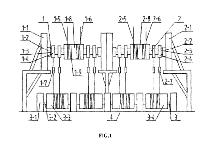
FIG. 1 is a front view of an overall structure of a tension adjusting device
for a
hoisting steel wire rope according to the present invention:
FIG. 2 is a side view of an overall structure of a tension adjusting device
for a
hoisting steel wire rope according to the present invention
FIG. 3 is a cross-sectional view of a primary left drum of the present
invention:
FIG. 4 is a cross-sectional view of a primary right drum of the present
invention;
FIG. 5 is a cross-sectional view of a secondary left drum of the present
invention:
FIG. 6 is a cross-sectional view of a secondary right drum of the present
invention: and
FIG. 7 is a stepped cross-sectional view of a secondary left drum and a
secondary
6
CA 3014564 2018-10-15
right drum of the present invention.
Meanings of reference numerals in the drawings are as follows: I. Primary left
steel wire rope tension adjusting device; 2. Primary right steel wire rope
tension
adjusting device; 3. Secondary steel wire rope tension adjusting device; 4.
Hoisting
container; 1-1. Primary left guide rail: 1-2. Primary left slider; 1-3.
Primary left
spindle; 1-4. Primary left connection block: 1-5. First hoisting steel wire
rope: 1-6.
Second hoisting steel wire rope; 1-7. Primary left steel wire rope connection
device;
1-8. Primary left drum; 1-9. Rope head lock block: 2-1. Primary right guide
rail; 2-2.
Primary right slider: 2-3. Primary right spindle; 2-4. Primary right
connection block;
2-5. Third hoisting steel wire rope; 2-6. Fourth hoisting steel wire rope; 2-
7. Primary
right steel wire rope connection device; 2-8. Primary' right drum; 3-1. Fixed
bearing
pedestal; 3-2. Secondary revolving shaft; 3-3. Secondary left drum; and 3-4.
Secondary right drum
DETAILED DESCRIPTION OF THE INVENTION
The present invention is further described below with reference to the
accompanying drawings and embodiments.
A tension adjusting device for a hoisting steel wire rope of an ultra-deep
vertical
shaft provided by' the present invention includes two stages of steel wire
rope tension
adjusting devices provided on a hoisting container. A primary steel wire rope
tension
adjusting device includes left and right steel wire rope tension adjusting
devices that
are symmetrically arranged, and the left and right steel wire rope tension
adjusting
devices each include guide rails, sliders, a spindle, connection blocks, and a
primary
drum. The guide rails, the sliders, and the connection blocks are successively
symmetrically arranged on two sides of the spindle, the drum is provided on
the
middle portion of the spindle, two hoisting steel wire ropes are
symmetrically' wound
around the drum, and rope head ends of the two hoisting steel wire ropes are
fixed to
the drum with rope head lock blocks. A secondary steel wire rope tension
adjusting
device is provided below the primary steel wire rope tension adjusting device,
and
includes a plurality of fixed bearing pedestals, revolving shafts, and
secondary drums,
where each revolving shaft is provided µN t h one secondary drum, two ends of
each
revolving shaft are disposed inside the fixed bearing pedestals respectively,
a steel
wire rope is wound around each secondary drum, and two ends of the steel wire
rope
7
CA 3014564 2018-10-15
are respectively connected to the connection blocks of the primary steel wire
rope
tension adjusting device via steel wire rope connection devices.
As shown in FIGs. 1 and 2. the left and right steel wire rope tension
adjusting
devices of the present invention specifically include a primary left steel
wire rope
tension adjusting device 1, a primary right steel wire rope tension adjusting
device 2.
and a secondary steel wire rope tension adjusting device 3. The primary left
steel '1N:ire
rope tension adjusting device 1 includes two primary left guide rails 1-1, two
primary
left sliders 1-2, a primary left spindle 1-3, one, two or three primary left
connection
blocks 1-4, a first hoisting steel wire rope 1-5 and a second hoisting steel
wire rope
1-6. a primary left drum 1-8. rope head lock blocks 1-9, and one, two or three
primary
left steel wire rope connection devices 1-7. The primary right steel wire rope
tension
adjusting device 2 includes two primary right guide rails 2-1, two primary
right sliders
2-2, a primary right spindle 2-3, one, two or three primary right connection
blocks 2-4,
a third hoisting steel wire rope 2-5 and a fourth hoisting steel wire rope 2-
6. a primary
right drum 2-8, and one, two or three primary right steel wire rope connection
devices
2-7. The secondary steel wire rope tension adjusting device 3 includes five
bearing
pedestals 3-1. four secondary revolving shafts 3-2, two secondary left drums 3-
3, and
two secondary right drums 3-4.
The primary left guide rails 1-1 are rectangular guide rails, and fastened to
the
hoisting container 4. The primary left sliders 1-2 are square blocks, and fit
snugly to
inner walls of the primary left guide rails 1-1. Two ends of the primary left
spindle
1-3 are fixedly connected to the two primary left sliders 1-2 respectively,
and move
up and down along the primary left guide rails 1-1 together. The primary left
drum
1-8 is mounted on a middle portion of the primary left spindle 1-3 via a
bearing, and
is provided with spiral grooves for the steel xvire ropes and lock blocks 1-9
for
fastening rope heads of the first hoisting steel wire rope 1-5 and the second
hoisting
steel wire rope 1-6. The first hoisting steel wire rope 1-5 is wound around
the primary
left drum 1-8 by four or more turns and extends upwards from the front side of
the
primary left drum 1-8, and the second hoisting steel wire rope 1-6 is wound
around.
the primary left drum 1-8 by four or more turns and extends upwards from the
back
side of the primary left drum 1-8. The primary left connection blocks 1-4 are
fastened
on two sides of the pnmary left drum 1-8. Each of the primary left steel wire
rope
connection devices 1-7 is connected upwards to one of the primary left
connection
S
CA 3014564 2018-10-15
blocks 1-4 via a steel wire rope, and a lower end thereof is fastened to a
secondary left
drum 3-3 by winding a steel wire rope from the front side of the drum.
The primary right guide rails 2-1 are rectangular guide rails, and fastened to
the
hoisting container 4. The primary right sliders 2-2 are square blocks, and fit
snugly to
inner walls of the primary right guide rails 2-1. Two ends of the primary
right spindle
2-3 are fixedly connected to the two primary right sliders 2-2 respectively,
and move
up and down along the primary right guide rails 2-1 together. The primary
right drum
2-8 is mounted on a middle portion of the primary right spindle 2-3 via a
bearing, and
is provided with
spiral grooves for the steel \ vire ropes and lock blocks 1-9 for
fastening rope heads of the third hoisting steel wire rope 2-5 and the fourth
hoisting
steel wire rope 2-6. The third hoisting steel wire rope 2-5 is wound around
the
primary right drum 2-8 by four or more turns and extends upwards from the
front side
of the primary right drum 2-8. and the fourth hoisting steel wire rope 2-6 is
wound
around the primary right drum 2-8 by four or more turns and extends upwards
from
the back side of the primary right drum 2-8. The primary right connection
blocks 2-4
are fastened on two sides of the primary right drum 2-8. Each of the primary
right
steel wire rope connection devices 2-7 is connected upwards to one of the
primary
right connection blocks 2-4 via a steel wire rope. and a lower end thereof is
fastened
to a secondary right drum 3-4 by winding a steel wire rope from the back side
of the
drum by four or more turns.
The bearing pedestals are fastened to the hoisting container 4. and the
secondary
revolving shafts 3-2 are mounted on the multiple bearing pedestals 3-1. The
secondary left drums 3-3 are mounted on the secondary revolving shafts 3-2 by
means
of a key connection and rotate in synchronization with the secondary revolving
shafts
3-2, and the secondary left drums 3-3 are each provided with spiral grooves
for the
steel wire ropes and lock blocks 1-9 for fastening rope heads of the steel
wire ropes.
The secondary right drums 3-4 are mounted on the secondary revolving shafts 3-
2 by
means of a key connection and rotate in synchronization with the secondary
revolving
shafts 3-2. and the secondary right drums 3-4 are each provided with spiral
grooves
for the steel wire ropes and lock blocks 1-9 for fastening rope heads of the
steel wire
ropes. The secondary left drum 3-3 and the secondary right drum 3-4 are
identical in
diameter.
As shown in FIG. 3 to FIG. 7, the present invention further provides a tension
9
CA 3014564 2018-10-15
adjusting method for a steel wire rope at a hoisting-container-end, which
includes the
following steps:
(1) Let a tensile force on a first hoisting steel wire rope 1-5 be F1 and a
tensile
force on a second hoisting steel wire rope 1-6 be F2. When FI=F2, a primary
left drum
1-8 is subject to balanced forces at two sides and does not rotate. When
FI>F,, a force
acting on a front side of the primary left drum 1-8 is greater than that on
its back side.
and the primary left drum 1-8 rotates counterclockwise, such that the first
hoisting
steel wire rope 1-5 is relatively loosened and F1 decreases, the second
hoisting steel
wire rope 1-6 is relatively tightened and F2 increases, so as to make Ft be
equal to F2
finally. When FI<F2, a force acting on a front side of the primary left drum 1-
8 is less
than that on its back side, and the primary left drum 1-8 rotates clockwise,
such that
the first hoisting steel wire rope 1-5 is relatively tightened and Fi
increases, the
second hoisting steel wire rope 1-6 is relatively loosened and F2 decreases,
so as to
make F1 be equal to F2 finally.
(2) Let a tensile force on a third hoisting steel wire rope 2-5 be F3 and a
tensile
force on a fourth hoisting steel wire rope 2-6 be F4. When F3=F4. a primary
right drum
2-8 is subject to balanced forces at two sides and does not rotate. When
F3>F4, a force
acting on a front side of the primary right drum 2-8 is greater than that on
its back side,
and the primary right drum 2-8 rotates counterclockwise, such that the third
hoisting
steel wire rope 2-5 is relatively loosened and F3 decreases, the fourth
hoisting steel
wire rope 2-6 is relatively tightened and F4 increases, so as to make F3 be
equal to F4
finally. When F3<F4, a force acting on a front side of the primary right drum
2-8 is
less than that on its back side, and the primary right drum 2-8 rotates
clockwise, such
that the third hoisting steel wire rope 2-5 is relatively tightened and F3
increases, the
fourth hoisting steel wire rope 2-6 is relatively loosened and F4 decreases,
so as to
make F3 be equal to F4 finally.
(3) When F1+F2=F3+4 a force acting on a front side of a secondary left drum
3-3 and a force acting on a back side of a secondary right drum 3-4 are
balanced, and
secondary revolving shafts 3-2 fixedly connected to both the secondary left
drum 3-3
and the secondary right drum 3-4 do not rotate. When F1+F2>F3-FF4, the force
acting
on the front side of the secondary left drum 3-3 is greater than the force
acting on the
back side of the secondary right drum 3-4, and the secondary revolving shafts
3-2
fixedly connected to both the secondary left drum 3-3 and the secondary right
drum
CA 3014564 2018-10-15
3-4 rotate counterclockwise, such that a steel wire rope on the front side of
the
secondary left drum is relatively loosened and the force thereon is reduced, a
steel
wire rope on the back side of the secondary right drum 3-4 is relatively
tightened and
the force thereon is increased, so as to make F1+F2 be equal to F3+F4 finally.
When
F1+F2<F3-44, the force acting on the front side of the secondary left drum 3-3
is less
than the force acting on the back side of the secondary right drum 3-4, and
the
secondary revolving shafts 3-2 fixedly connected to both the secondary left
drum 3-3
and the secondary right drum 3-4 rotate clockwise, such that a steel wire rope
on the
front side of the secondary left drum is relatively tightened and the force
thereon is
increased, a steel wire rope on the back side of the secondary right drum 3-4
is
relatively loosened and the force thereon is reduced, so as to make
F1+F2=F3+E4
II
CA 3014564 2018-10-15