Note: Descriptions are shown in the official language in which they were submitted.
CA 03014673 2018-08-14
WO 2017/156208 PCT/US2017/021483
1
ABSORBENT ARTICLES
FIELD OF THE INVENTION
The disclosure herein relates generally to material webs and articles
incorporating
material webs.
BACKGROUND OF THE INVENTION
Nonwoven webs have been used in a myriad of disposable absorbent articles over
the
years. For example, in some particular absorbent articles, e.g. diapers and
feminine hygiene
pads, nonwovens may be utilized as a topsheet, backsheet, or some other
feature of these
particular absorbent articles.
Unfortunately, the requirements for absorbent articles may be disparate
depending on use.
For example, a nonwoven web used as a topsheet for baby diapers may not be
suitable for adult
incontinence products. Similarly, a nonwoven web suitable as a topsheet for
adult incontinence
.. products may not be suitable for feminine hygiene pads.
Additionally, requirements for nonwoven webs in disposable absorbent articles
may vary
by geography. For example, in one geography an absorbent article with a soft
topsheet may be a
factor which is foremost in consumer's minds. In another geography, absorbent
articles which
minimize the amount of rewet may be foremost in consumer's minds. In yet
another geography,
the speed of acquisition of liquid insults may be foremost in consumer's
minds.
It would be beneficial for a material web to address one or more of the above
concerns. It
would also be beneficial to have a process which facilitated the production of
material webs
capable of addressing one or more of the above concerns.
SUMMARY OF THE INVENTION
Disclosed herein are material webs, which may include spunbond, meltblown and
combinations thereof, which can be used in disposable absorbent articles. Some
exemplary uses
include topsheet, acquisition layer or overwrap for a tampon. The material
webs of the present
invention, when utilized for example as a topsheet of a feminine hygiene
article or other
absorbent article, can provide a soft feel to the user and can provide quick
acquisition of
menstrual and/or urine insults. Other benefits and configurations in these and
other disposable
absorbent articles are discussed hereinafter.
CA 03014673 2018-08-14
WO 2017/156208 PCMJS2017/021483
2
BRIEF DESCRIPTION OF THE DRAWINGS
While the specification concludes with claims particularly pointing out and
distinctly
claiming the subject matter of the present invention, it is believed that the
invention can be more
readily understood from the following description taken in connection with the
accompanying
drawings, in which:
Figure 1 is a schematic representation of a cross section of a material web of
the present
invention.
Figure 2 is a schematic representation of a process for making a spunmelt
nonwoven web
of the present invention.
Figures 3A-3C are schematic illustrations of cross sections of bi-component
filaments for
use with the present invention.
Figure 4A is an illustration of an exemplary straight filament.
Figure 4B is an illustration of an exemplary curled filament.
Figure 5A is a schematic representation of a material web of the present
invention shown
in plan view.
Figure 5B is a schematic representation of the material web of Figure 5A shown
in cross
section along line 5B-5B.
Figure 5C is a schematic representation of the material web of Figure 5A shown
in cross-
section along line 5C-5C.
Figure 5D is a schematic representation of another form of the material web of
Figure 5A
shown in cross-section.
Figure 5E is a schematic representation of another form of the material web of
Figure 5A
shown in cross-section.
Figures 6A-6E are schematic representations of tunnel tufts on material webs
of the
present invention.
Figures 7A-7D are schematic representations of filled tufts on material webs
of the
present invention.
Figure 8A is a plan view photomicrograph showing one side of a material web
having
three-dimensional discontinuity formed therein in accordance with the present
disclosure.
Figure 8B is a plan view photomicrograph showing the other side of the
material web of
Figure 8A, with the openings.
Figure 8C is a perspective view of a discontinuity in a two layer material web
in
accordance with the present disclosure.
CA 03014673 2018-08-14
WO 2017/156208 PCT/1JS2017/021483
3
Figure 8D is a schematic view of a nested tuft in accordance with the present
disclosure.
Figure 9A-9D are schematic representations of corrugations and grooves on
material
webs of the present invention.
Figures 10-14 are schematic illustrations of disposable absorbent articles
comprising a
plurality of zones in accordance with the present invention.
Figures 15A-15B are SEM photos of a first plurality of filaments of a first
stratum and a
second plurality of filaments of a second stratum, respectively.
Figure 15C is an SEM photo of a material web constructed in accordance with
the present
invention.
Figure 16A is a photo of a material web comprising apertures, wherein the
material web
is constructed in accordance with the present invention.
Figure 16B is a photo of a nonwoven laminate comprising a hydrophobic first
layer and a
hydrophilic second layer.
Figure 17A is a photo of a material web comprising tunnel tufts, wherein the
material web
is constructed in accordance with the present invention.
Figure 17B is a photo of a nonwoven laminate comprising a hydrophobic first
layer and a
hydrophilic second layer.
Figure 18 is a depiction of a coordinate system for the material webs of the
present
invention.
Figures 19-32 are photographs of material webs comprising patterned apertures
in
accordance with the present invention.
Figure 33 shows a plan view of a feminine hygiene pad constructed in
accordance with
the present disclosure.
Figure 34 shows a plan view of a diaper constructed in accordance with the
present
disclosure.
Figure 35 shows a cross section of the diaper of Figure 34 taken along lines
35-35.
Figure 36 shows a cross section of the diaper of Figure 35 in an expanded
state.
Figure 37 is an isometric view of an exemplary material web with corrugations
therein
constructed in accordance with the present disclosure.
Figure 38 is an isometric view of an exemplary material web with corrugations
therein
constructed in accordance with the present disclosure.
Figure 39 is an isometric view of an exemplary material web with corrugations
therein
constructed in accordance with the present disclosure.
CA 03014673 2018-08-14
WO 2017/156208 PCMJS2017/021483
4
Figure 40 is a cross-sectional view of a material web of material in a three
strata
configuration in accordance with the present disclosure.
Figure 41 is a perspective view of the web of material of Figure 40 with
various portions
of nonwoven component strata cut away to show the composition of each nonwoven
component
.. stratum in accordance with the present disclosure.
Figure 42 is a cross-sectional view of a material web in a four stratum
configuration in
accordance with the present disclosure.
Figure 43 is a perspective view of the material web of Figure 42 with various
strata of
material web cut away to show the composition of each nonwoven stratum in
accordance with
the present disclosure.
Figure 44 is a schematic representation of a cross section of a material web
of the present
invention.
DETAILED DESCRIPTION OF THE INVENTION
As used herein "disposable absorbent article" or "absorbent article" shall be
used in
reference to articles such as diapers, training pants, diaper pants,
refastenable pants, adult
incontinence pads, adult incontinence pants, feminine hygiene pads, tampons,
and pessary
devices. The term "disposable article" shall be used in reference to articles
such as facemasks.
For ease of discussion, the terms "disposable absorbent article" or "absorbent
article" will be
used; however, the material webs of the present invention may equally be
utilized in facemasks
unless otherwise specified.
As used herein "hydrophilic" and "hydrophobic" have meanings well established
in the
art with respect to the contact angle of a referenced liquid on the surface of
a material. Thus, a
material having a liquid (water) contact angle of greater than about 90
degrees is considered
hydrophobic, and a material having a liquid (water) contact angle of less than
about 90 degrees is
considered hydrophilic. Compositions which are hydrophobic, will increase the
contact angle of
water on the surface of a material while compositions which are hydrophilic
will decrease the
contact angle of water on the surface of a material. Notwithstanding the
foregoing, reference to
relative hydrophobicity or hydrophilicity between material(s) and/or
composition(s) does not
imply that the material or composition are hydrophobic or hydrophilic. For
example, a
composition may be more hydrophobic than a material. In such a case neither
the composition
nor the material may be hydrophobic; however, the contact angle of water
droplets on the
composition is greater than that of water droplets on the material. As another
example, a
CA 03014673 2018-08-14
WO 2017/156208 PCMJS2017/021483
composition may be more hydrophilic than a material. In such a case, neither
the composition
nor the material may be hydrophilic; however, the contact angle with respect
to water droplets
exhibited by the composition may be less than that exhibited by the material.
As used herein, "spunbond filaments" refers to small diameter filaments which
are formed
5 by
extruding molten thermoplastic material as filaments from a plurality of fine
capillaries of a
spinneret with the diameter of the extruded filaments then being rapidly
reduced. Spunbond
filaments are generally not tacky when they are deposited on a collecting
surface. Spunbond
filaments are generally continuous and have average diameters (from a sample
of at least 10
measurements) larger than 7 microns, and more particularly, between about 8
and 40 microns.
The term "filament" refers to any type of artificial continuous strand
produced through a
spinning process, a meltblowing process, a melt fibrillation or film
fibrillation process, or an
electrospinning production process, or any other suitable process to make
filaments. The term
"continuous" within the context of filaments are distinguishable from staple
length fibers in that
staple length fibers are cut to a specific target length. In contrast,
"continuous filaments" are not
cut to a predetermined length, instead, they can break at random lengths but
are usually much
longer than staple length fibers.
By "substantially randomly oriented" it is meant that, due to processing
conditions of
laying down multiple filaments onto a collecting surface (e.g. a moving
foraminous belt with
vacuum suction underneath) for forming of a nonwoven web, those filaments are
touching down
and tipping over onto the collecting surface following turbulent, chaotic,
random movements so
that the direction of a section of a filament can go into any direction on a
360 circle ¨ as
laydown direction. The laydown orientation may be more common in the machine
direction
(MD) than the cross direction (CD), or vice-versa as can be analyzed via a
histogram of fiber
orientation distribution.
Each of the material webs of the present invention comprises at least two
strata. As used
herein, the term "strata" and "stratum" refer to the layered regions which
make up a unitary
structure, which in the case of the present invention is the material web. The
combination of
strata of the material web is not an assembly or laminate of preformed layers
forming a multi-
layered structure. Rather the material web of the present invention is
constructed by assembling
the strata in an integral manner as described herein. In some forms, where
adjacent strata are
indistinguishable, the adjacent strata may be considered to be a stratum.
The ideas and techniques described herein for forming the material webs of the
present
invention can be applied to spunbond filaments and/or fine fiber / nanofiber
webs with multiple
CA 03014673 2018-08-14
WO 2017/156208 PCMJS2017/021483
6
strata; which in turn may be comprised within a spunmelt web. Continuous and
discontinuous
fiber spinning technologies of molten materials and typically of
thermoplastics are commonly
referred to as spunmelt technologies. Spunmelt technologies may comprise both
the meltblowing
process and spunbonding processes. A spunbonding process comprises supplying a
molten
polymer, which is then extruded under pressure through a large number of
orifices in a plate
known as a spinneret or die. The resulting continuous fibers are quenched and
drawn by any of a
number of methods, such as slot draw systems, attenuator guns. or Godet rolls,
for example. In
the spunlaying or spunbonding process, the continuous fibers are collected as
a loose web upon a
moving foraminous surface, such as a wire mesh conveyor belt, for example.
When more than
one spinneret is used in line for forming a multi-strata web, the subsequent
nonwoven component
strata are collected upon the uppermost surface of the previously formed
nonwoven component
strata.
As used herein, "fine fibers" and "nanofibers" shall be used synonymously and
shall refer
to filaments or fibers which have a diameters of less than about 8 microns.
For example,
meltblown filaments can have a diameter between 2 to 8 microns while other
filament making
methods can product sub-micron diameter filaments as discussed hereafter.
Methods to produce fine fibers or nanofibers comprise melt fibrillation and
electrospinning. Melt fibrillation is a general class of making fibers defined
in that one or more
polymers are molten and are extruded into many possible configurations (e.g.,
co-extrusion,
homogeneous or bi-component films or filaments) and then fibrillated or
fiberized into filaments.
Meltblowing is one such specific method (as described herein).
The meltblowing process is related to the spunbonding process for forming a
stratum of a
nonwoven material, wherein, a molten polymer is extruded under pressure
through orifices in a
spinneret or a die. High velocity gas impinges upon and attenuates the fibers
as they exit the die.
The energy of this step is such that the formed fibers are greatly reduced in
diameter and are
fractured so that micro-fibers of indeterminate length are produced. This
differs from the
spunbonding process where the continuity of the fibers are generally
preserved. Often meltblown
nonwoven structures are added to spunbond nonwoven structures to form
spunbond, meltblown
("SM") webs or spunbond, meltblown, spunbond ("SMS") webs, which are strong
webs with
some barrier properties. Coaxial meltblown is known in the art and is
considered a form of
meltblowing.
Melt film fibrillation is another method that may be used to produce
nanofibers, i.e.
submicron fibers. A melt film is produced from the melt and then a fluid is
used to form fibers
CA 03014673 2018-08-14
WO 2017/156208 PCMJS2017/021483
7
from the melt film. Examples of this method comprise U.S. Patent Nos.
6,315,806, 5,183,670,
and 4,536,361, to Torobin et al., and U.S. Patent Nos. 6,382,526, 6,520,425,
and 6,695,992, to
Reneker et al. and assigned to the University of Akron, and U.S. Patent Nos.
8,395,016;
8,487,156; 7,291 300; 7,989,369; and 7,576,019. The process according to
Torobin uses one or
an array of co-annular nozzles to form a tube of film which is fibrillated by
high velocity air
flowing inside this annular film. Other melt film fibrillation methods and
systems are described
in the U.S. Pat. Publ. No. 2008/0093778, to Johnson, et al., published on
April 24, 2008, U.S.
Pat. No. 7,628,941, to Krause et al., and U.S. Pat. Publ. No. 2009/0295020, to
Krause, et al.,
published on December 3, 2009 and provide uniform and narrow fiber
distribution, reduced or
minimal fiber defects such as unfiberized polymer melt (generally called
"shots"), fly, and dust,
for example. These methods and systems further provide uniform nonwoven webs
for absorbent
hygiene articles.
Electrospinning is another commonly used method of producing sub-micron
fibers. In
this method, typically, a polymer is dissolved in a solvent and placed in a
chamber sealed at one
end with a small opening in a necked down portion at the other end. A high
voltage potential is
then applied between the polymer solution and a collector near the open end of
the chamber. The
production rates of this process are very slow and fibers are typically
produced in small
quantities. Another spinning technique for producing sub-micron fibers is
solution or flash
spinning which utilizes a solvent.
So, in the context of the material webs of the present invention, a first
nonwoven stratum
may be integrally formed with a second nonwoven stratum. However, material
webs of the
present invention are not limited to nonwovens. Additionally, the material
webs of the present
invention may comprise a film strata in conjunction with a nonwoven strata
described above.
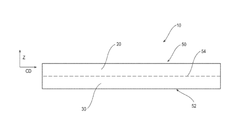
An exemplary web is shown in Figure 1. As shown in Figure 1, material webs 10
of the
present invention have a machine direction (MD) (perpendicular to the plane of
the sheet
showing Figure 1), a cross machine direction (CD), and a Z direction
(thickness direction), as is
commonly known in the art of web manufacture. As shown, the material web 10
comprises at
least a first stratum 20 and a second stratum 30. The material web 10 further
comprises a first
surface 50 and a second surface 52. As discussed herein, the first stratum 20
and the second
stratum 30 are integrally formed. For example, the first stratum 20 and the
second stratum 30
may be integrally formed via a spunmelt, melt blowing, or electrospinning
processes described
herein.
CA 03014673 2018-08-14
WO 2017/156208 PCMJS2017/021483
8
Additionally, in some forms of the present invention, each of the first
stratum 20 and the
second stratum 30 comprise a plurality of randomly oriented filaments. For
example, the first
stratum 20 may comprise a first plurality of randomly oriented filaments, and
the second stratum
30 may comprise a second plurality of randomly oriented filaments. For ease of
visualization, a
delineation 54 is shown between the first stratum 20 and second stratum 30;
however, as the first
stratum 20 and second stratum 30 are integrally formed, as described herein, a
delineation
between adjacent strata may not be so easily detectable. But, as noted
previously, in some forms,
the first stratum 20 or the second stratum 30 may comprise a film.
For the material webs 10 of the present invention, the first stratum 20 is
different than the
second stratum 30. As shown in Figure 1, such a configuration creates a Z-
direction
characteristic difference that is measurable as disclosed herein. In the
creation of a Z-direction
characteristic difference, the first stratum 20 may differ from the second
stratum 30 in a myriad
of ways. Some suitable examples include surface energy, thickness, filament
diameter, filament
cross-sectional area, filament cross-sectional shape, filament cross sectional
configuration with
multiple polymers (such as for example "bico"), filament curl, and/or filament
composition,
softness, coefficient of friction, extensibility and/or color. Each of the
foregoing represent a
characteristic of the filaments of the strata or of the strata itself. And
each is discussed hereafter
in additional detail.
Each of these variables can impact the performance attributes of absorbent
articles in
various ways. For example, acquisition speed, reduction of rewet, creation of
barrier properties,
better conformance of the product, increase in softness, etc.
Additionally, the material webs 10 of the present invention, may comprise an
MD and/or
CD characteristic difference that is measurable as disclosed herein. In the
creation of the MD
and/or CD characteristic differences, the first stratum 20 and/or second
stratum 30 may comprise
a myriad of features. For example, apertures, bond sites, embossments tunnel
tufts, filled tufts,
nested tufts, outer tufts, and corrugations can provide an MD and/or CD
characteristic difference.
Material web ¨ Z-direction characteristic differences
The modification of strata characteristics, as noted above, can create Z-
direction
characteristic differences in the material web 10 which can enhance certain
properties of the
material webs 10. For example, acquisition time, rewet, permeability,
softness, masking,
resiliency, and capillarity are some of the properties which can be modified
based upon the
differences in the first plurality of filaments and the second plurality of
filaments. The
CA 03014673 2018-08-14
WO 2017/156208 PCMJS2017/021483
9
differences between the first stratum 10 and the second stratum 30 are
discussed hereafter along
with the benefits in the properties of the material web.
Referring now to Figures 1 and 2, a material web of the present invention may
be
produced via a spunbond process comprising multiple spinbeams 255, 257. In
some forms, the
first spinbeam 255 may deposit a first plurality of filaments 261 onto a belt.
The second
spinbeam 257 may deposit a second plurality of filaments 263 onto the belts
over the top of the
first plurality of filaments 261. And, as noted previously, the second
plurality of filaments may
be configured differently than the first plurality of filaments such that the
first stratum 20 is
different than the second stratum 30.
Forms of the present invention are contemplated where additional spinbeams are
provided
to provide additional strata with additional filaments. Accordingly, material
webs of the present
invention may comprise a third stratum a fourth stratum and so on. And, the
strata of the
material web may be configured such that at least two of the strata are
different. Additionally,
forms of the present invention are contemplated where processes for the
material webs may allow
for the inclusion of one or more nanofiber strata, e.g. one or more meltblown
strata, one or more
melt fibrillation strata, and/or one or more electrospun strata.
Additionally, forms of the present invention are contemplated where the first
stratum 20
is created in a first step and subsequently processed. Subsequently, the
second stratum 30 may
be deposited onto the first stratum 20. For example, the first stratum may be
provided to an
aperturing process (described herein) and subsequently, the second stratum may
be integrally
formed on the first stratum via the processes described herein. As another
example, the first
stratum may comprise a film. The first stratum may be subjected to an
aperturing process
(described herein) and subsequently, the second stratum may be integrally
formed on the first
stratum via the processes described herein. As another example, the first
stratum may comprise a
nonwoven which is subjected to an aperturing process (described herein), and
subsequently, the
second stratum which comprises a film is integrally formed on the first
stratum, e.g. extruded
onto the first nonwoven stratum. And, as yet another example, the first
stratum and the second
stratum may be integrally formed without any intermediate processing of the
first stratum or
second stratum.
Surface Energy
One of the ways to create a Z-direction characteristic difference in the
material webs of
the present invention is to utilize differing surface energies for the first
stratum 20 and/or second
CA 03014673 2018-08-14
WO 2017/156208 PCMJS2017/021483
stratum 30 (and/or of any additional strata). In general, nonwoven strata
which have a high
surface energy may be considered to be more hydrophilic than nonwoven strata
which have a low
surface energy. That said, in some forms of the present invention, the first
stratum 20 may be
more phobic than the second stratum 30. Accordingly, in some forms, the first
stratum 20 may
5 have a lower surface energy than the second stratum 30.
The increased phobicity of the first stratum 20 (relative to the second or any
other
stratum) may be achieved in a variety of ways. For example, the first
plurality of filaments may
comprise a composition which is more phobic than that of the second plurality
of filaments. In
one specific example, the first plurality of filaments may comprise
polyethylene while the second
10 plurality of filaments comprise polyethylene terephthalate. In general,
polyethylene and
polypropylene are more phobic than polylactic acid, polyethylene terephthalate
and nylon. The
first plurality of filaments and/or second plurality of filaments may use any
suitable combination
of these compositions.
In another example, the first plurality of filaments and/or second plurality
of filaments
may comprise a melt additive. In one specific example, the first plurality of
filaments may
comprise a phobic melt additive added directly or as master batch to the
polymer melt during
spinning of the first plurality of filaments. Such a melt-additive could
comprise for example lipid
esters or polysiloxanes. For those forms where the additive is melt blended
into the filaments, the
additive can bloom to the surface of the filaments and create a film covering
a portion of the
external surface of the filament and/or can create fibrils, flakes, particles,
and/or other surface
features. In conjunction with the phobic melt additive or independent
therefrom, the second
plurality of filaments may comprise a philic melt additive. In another
example, the first plurality
of filaments may comprise a phobic melt additive at a first weight percent
while the second
plurality of filaments may comprise a phobic melt additive at a second weight
percent. The first
weight percent may be greater than the second weight percent such that the
first stratum 20 is
more phobic than the second stratum 30. In yet another example, the first
plurality of filaments
may comprise a philic melt additive at a first weight percent and the second
plurality of filaments
may comprise a philic melt additive at a second weight percent. In such forms,
the second
weight percent may be greater than the first weight percent such that the
second stratum 30 is
.. more philic than the first stratum 20. In yet another example, the first
plurality of filaments may
comprise a first phobic melt additive while the second plurality of filaments
comprise a second
phobic melt additive. In such forms, the first phobic melt additive may render
the first plurality
of filaments more phobic than the second plurality of filaments or vice versa.
In yet another
CA 03014673 2018-08-14
WO 2017/156208 PCMJS2017/021483
11
example, the first plurality of filaments may comprise a first philic melt
additive while the second
plurality of filaments comprise a second philic melt additive. In such form,
the first philic melt
additive may render the first plurality of filaments more philic than the
second plurality of
filaments or vice versa.
For those forms where melt additives are provided to the first plurality of
filaments and/or
the second plurality of filaments, the melt additive may preferably form
between about 0.11
percent by weight to about 20 percent by weight of the first stratum 20 and/or
second stratum 30.
In some forms, the melt additives are more preferably less than about 15
percent by weight, even
more preferably less than about 10 percent by weight, and most preferably less
than about 8
percent by weight, specifically including any values within these ranges or
any ranges created
thereby.
Any suitable phobic melt additive may be utilized. Examples of phobic melt
additives
include fatty acids and fatty acid derivatives. The fatty acids may originate
from vegetable,
animal, and/or synthetic sources. Some fatty acids may range from a C8 fatty
acid to a C30 fatty
acid, or from a C12 fatty acid to a C22 fatty acid. In other forms, a
substantially saturated fatty
acid may be used, particularly when saturation arises as a result of
hydrogenation of fatty acid
precursor. Examples of fatty acid derivatives include fatty alcohols, fatty
acid esters, and fatty
acid amides. Suitable fatty alcohols (R-OH) include those derived from C12-C28
fatty acids.
Suitable fatty acid esters include those fatty acid esters derived from a
mixture of C12-
C28 fatty acids and short chain (C1-C8, preferably CI-C3) monohydric alcohols
preferably from
a mixture of C12-C22 saturated fatty acids and short chain (C1-C8, preferably
C1-C3)
monohydric alcohols.. The hydrophobic melt additive may comprise a mixture of
mono, di,
and/or tri-fatty acid esters. An example includes fatty acid ester with
glycerol as the backbone as
illustrated in 1_11.
.1)
0
Rr- u 0
[1]
CA 03014673 2018-08-14
12
where RI, R2, and R3 each is an alkyl ester having carbon atoms ranging from
11 to 29. In some
forms, the glycerol derived fatty acid ester has at least one alkyl chain, at
least two, or three
chains to a glycerol, to form a mono, di, or triglyceride. Suitable examples
of triglycerides
include glycerol thibehenate, glycerol tristearate, glycerol tripalmitate, and
glycerol trimyristate,
and mixtures thereof. In the case of triglycerides and diglycerides, the alkyl
chains could be the
same length, or different length. Example includes a triglyceride with one
alkyl C18 chain and
two C16 alkyl chain, or two C18 alkyl chains and one C16 chain. Preferred
triglycerides include
alkyl chains derived from C14-C22 fatty acids.
Suitable fatty acid amides include those derives from a mixture of Cl 2-C28
fatty acids
(saturated or unsaturated) and primary or secondary amines. A suitable example
of a primary
fatty acid amide includes those derived from a fatty acid and ammonia as
illustrated in [2].
0
RNH2
[2]
where R has a number of carbon atoms ranging from 11 to 27. In at least one
other form,
the fatty acids may range from a C16 fatty acid to a C22 fatty acid. Some
suitable examples
include erucamide, oleamide and behanamide. Other suitable hydrophobic melt
additives include
hydrophobic silicones. Additional suitable phobic melt additives are disclosed
in U.S. Patent
Publication No. 2016-0067118 and U.S. Patent Publication No. 2016-0167334.
Another suitable
phobic melt additive is available from Techmer PM in Clinton, TN under the
trade name
PPM17000 High Load Hydrophobic. One specific example of a phobic melt additive
is glycerol
tristearate. As used herein, glycerol tristearate is defined as a mixture of
long-chained
triglycerides containing predominately C18 and C16 saturated alkyl chain
lengths. Additionally
there could be varying degrees of unsaturation and cis to trans unsaturated
bond configurations.
The alkyl chain lengths could range from about CIO to about C22. The degrees
of unsaturation
typically will range from 0 to about 3 double bonds per alkyl chain. The ratio
of cis to trans
unsaturated bond configurations can range from about 1:100 to about 100:1.
Other suitable
examples for use with polypropylene and/or polyethylene, a triglyceride which
contains either
stearic acid or pahnic acid or both as the fatty acid components, or a mixture
of such
triglycerides. Other
suitable hydrophobic melt additives may comprise erucamide or
polysiloxanes.
Any suitable philic additive can be used. Some suitable examples include those
available
from Techmer PM, Clinton, TN sold under the trade name of Techmer PPM15560;
TPM12713,
CA 03014673 2018-08-14
WO 2017/156208 PCMJS2017/021483
13
PPM19913, PPM 19441, PPM19914õ PPM112221 (for polypropylene), PM19668,
PM112222
(for polyethylene). Additional examples are available from Polyvel Inc.
located in Hammonton,
NJ, sold under the trade name of Polyvel VW351 PP Wetting Agent (for
polypropylene); from
Goulston Technologies Inc. located in Monroe, NC sold under the trade name
Hydrosorb 1001;
as well as those philic additives disclosed in US Patent Application
Publication No.
2012/0077886 and U.S. Patent Nos. 5,969,026 and U.S. Patent No. 4,578,414.
Nucleating agents may be included along with the melt additives. Nucleating
agents can
help to drive more or faster blooming of either a philic or phobic melt
additive. Thus it would
create a characteristic difference in the Z-Direction even when the same
phobic or philic melt-
additive is used for all of the strata: the nucleating agent when added to one
or less than all of the
strata will produce a more intensive philic or phobic effect or contact angle
effect (depending on
the type of additive in those strata) than the stratum or strata with the same
philic or phobic melt-
additive but that doesn't (or don't) contain the nucleating agent. Suitable
nucleating agents may
be comprised of a nonitol, a trisamide and/or a sorbitol-based nucleating
agent. Specific but non-
limiting examples are: organic nucleation agents such as Millad NX 8000 or (in
its new trade
name) NX UltraClear GP110B from the Milliken company. An example of an
effective
inorganic nucleating agent is CaCO3, or other and especially nano-clay or nano-
scale mineral
molecules.
For those forms where the first plurality of filaments comprise a hydrophobic
melt
additive, the material web may be incorporated into a disposable absorbent
article as a topsheet
or overwrap in the case of a tampon. While conventional wisdom would typically
advise against
a hydrophobic topsheet, material webs of the present invention may comprise
apertures which
allow for rapid acquisition of liquid insults. In such forms, hydrophobic
topsheets can provide a
clean dry surface against a wearer's skin. Additionally, the hydrophobic
treatment in the first
plurality of filaments may reduce liquid rewet. Examples of the material webs
of the present
invention comprising hydrophobic and hydrophilic melt additives are provided
in the
"EXAMPLES" section of this specification.
And, while conventional wisdom may promote post-filament-production
enhancement of
hydrophobicity / hydrophilicity, e.g. topical application, applications of
such compositions may
be cause additional strife. For example, many topically applied treatments can
migrate to other
structures within an absorbent article. Or, for the material webs of the
present invention, post- -
production treatment may migrate from the first stratum 20 to the second
stratum 30 or vice versa
CA 03014673 2018-08-14
WO 2017/156208 PCMJS2017/021483
14
during application. Such migration could disturb the desired surface energy
difference between
the first stratum 20 and the second stratum 30.
However, forms are contemplated where the first stratum 20 is produced and
subsequently treated with a surface energy modifying composition.
Subsequently, the second
stratum 30 is formed onto the first stratum 20.
Filament Diameter or Cross-sectional Area
Another way to create Z-direction characteristic difference in the material
webs of the
present invention is to utilize differing filament sizes in the first
plurality of filaments versus the
second plurality of filaments in the first stratum 20 and second stratum 30,
respectively. The
term "filament size", refers to the cross-sectional dimension, diameter or
area of the filament; for
a circular-round cross-sectional shape the cross-sectional dimension is the
diameter and the area
is a circle, but there can be more complicated cross-sectional shapes. The
first stratum 20 and
second stratum 30 may comprise filament size differences in addition to or
independent from the
surface energy differences discussed above.
In some forms, the first plurality of filaments may comprise a first size
while the second
plurality of filaments comprise a second size. The first size may be different
than the second
size. In sonic forms, the first size may be greater than the second size. The
first plurality of
filaments and the second plurality of filaments may comprise any suitable
size. In some forms,
the first plurality of filaments and the second plurality of filaments can
have an average size in
the range of about 8 microns to about 40 microns, or a filament titer in the
range from 0.5 to 10
denier, specifically including all values within these ranges and any ranges
created thereby.
Generally, nonwoven webs with larger filaments increase permeability. The
increase in
permeability can provide quicker fluid penetration or transfer or acquisition
times which can be a
desirable quality. However, the increase in permeability may unfortunately
increase the potential
for liquid rewet.
In contrast, nonwoven webs with smaller filaments typically have lower
permeability but
higher capillarity. The lower permeability can mean slower fluid acquisition
times; however, the
higher capillarity can reduce the likelihood of rewet which can be desirable.
For those forms of the present invention where the material web 10 is utilized
as a
topsheet, a larger filament size in the first stratum 20 can mean higher
permeability ¨ quicker
fluid acquisition and lower capillarity. And, a smaller filament size in the
second stratum 30 can
mean lower permeability but higher capillarity ¨ reducing the likelihood of
rewet. Where the
CA 03014673 2018-08-14
WO 2017/156208 PCMJS2017/021483
material webs of the present invention comprise additional strata, the
additional strata can further
enhance the capillarity / permeability of the material web. For example, the
third stratum may
comprise filament sizes which are smaller than the second stratum and the
fourth stratum may
comprise smaller filament sizes than the third stratum. Accordingly, each of
the subsequent
5 strata may have increased capillarity. In such forms, a capillary
gradient can be configured
where the capillarity increases for those strata nearer the absorbent core.
Filament Cross Sectional Shape
Still another way to create Z-direction characteristic difference in the
material webs of the
10 present invention is to utilize differing filament cross-sectional
shapes. The first plurality of
filaments and/or second plurality of filaments may comprise any suitable cross-
sectional shape.
In some forms, the first plurality of filaments may comprise a shape that is
different than that of
the second plurality of filaments. Still in other forms, the first plurality
of filaments may
comprise a plurality of shapes and at least one of the shapes of the first
plurality of filaments is
15 different than the shape of the second plurality of filaments.
Similarly, the second plurality of
filaments may comprise a plurality of shapes.
The first plurality of filaments and/or the second plurality of filaments may
comprise a
non-round filaments. (Round meaning typically circular and solid without
cavities or hollow
sections.) As used herein, the term "non-round filaments" describes filaments
having a non-round
cross-section, and includes "shaped filaments" and "capillary channel
filaments." Such filaments
can be solid or hollow, and they can be tri-lobal, delta-shaped, and can be
filaments having
capillary channels on their outer surfaces. The capillary channels can be of
various cross-
sectional shapes such as "U-shaped", "H-shaped", "C-shaped" and "V-shaped".
One practical
capillary channel filament is T-401, designated as 4DG filament available from
Filament
Innovation Technologies, Johnson City, TN. T-401 filament is a polyethylene
terephthalate
(PET polyester). Other suitable shapes include round, round hollow, or ribbon.
The cross sectional shape of the first plurality of filaments and/or second
plurality of
filaments may be varied in conjunction with or independently of the surface
energy and filament
diameter / cross-sectional area differences discussed above.
Generally, non-round filaments have increased capillarity / wicking potential
than their
round filament counterparts due to their higher surface area. That said, non-
round filaments may
not readily give up the fluid which is disposed thereon. As such, non-round
filaments may not be
beneficial for the purposes of masking / rewet in a wearer-facing surface of a
material web.
CA 03014673 2018-08-14
WO 2017/156208 PCMJS2017/021483
16
Instead, the non-round filaments may perform much better if provided subjacent
to the wearer-
facing surface of an absorbent article. Additionally, non-round filaments have
greater wicking
ability, higher capillary suction and provide more resiliency than their round
filaments
counterparts. Each of these traits may provide more benefit if provided in a
stratum which is
closer to an absorbent core than a stratum which comprises a portion of the
wearer-facing surface
of an absorbent article.
In some specific forms, the first stratum 20 may comprise round filaments
while the
second stratum 30 comprises non-round filaments. Forms of the present
invention are
contemplated where the first stratum 30 and/or second stratum 40 have mixed
filament shapes.
For example, the first stratum 20 may comprise a higher percentage of round
filaments than does
the second stratum 30. And for those forms of the present invention which
comprise additional
strata, the third stratum may comprise non-round filaments and/or may comprise
a lower
percentage of round filaments than the second stratum 30. And, if a fourth
stratum is provided,
the fourth stratum may similarly comprise non-round filaments and/or may
comprise a lower
percentage of round filaments than the second stratum 30.
Additional forms are contemplated where the first stratum 20 and the second
stratum 30
each comprise round filaments. The third stratum may comprise non-round
filaments. In other
forms, the third stratum may comprise round filaments and a fourth stratum may
comprise non-
round filaments.
Filament Cross-Sectional Configuration
Still another way to create Z-direction characteristic differences in the
material webs of
the present invention is to utilize differing filament cross-sectional
configurations. For example,
the filaments of the first stratum and/or the second stratum can be mono-
component, bi-
component, and/or hi-constituent. As used herein, the term "mono-component"
filament refers to
a filament formed from one extruder using one or more polymers. This is not
meant to exclude
filaments formed from one polymer to which small amounts of additives have
been added for
coloration, antistatic properties, lubrication, hydrophilicity, etc.
As used herein, the term "hi-component filaments" refers to filaments which
have been
formed from at least two different polymers extruded from separate extruders
but spun together
to form one filament. Bi-component filaments are also sometimes referred to as
conjugate
filaments or multi-component filaments. The polymers are arranged in
substantially constantly
positioned distinct zones across the cross-section of the hi-component
filaments and extend
CA 03014673 2018-08-14
WO 2017/156208 PCMJS2017/021483
17
continuously along the length of the hi-component filaments. The configuration
of such a hi-
component filament may be, for example, a sheath/core arrangement wherein one
polymer is
surrounded by another, or may be a side-by-side arrangement, a pie
arrangement, or an "islands-
in-the-sea" arrangement. Some suitable examples of hi-component filament
configurations are
shown in Figures 3A-3C. For example, filaments of the material webs of the
present invention
may comprise filaments having a cross section 300 which comprises a first
component 300A and
a second component 300B arranged in a side by side configuration. As shown, a
delineation 302
between the first component 300A and 300B may be easily discernable depending
on the
compositions of the first component 300A and the second component 300B. In
some forms, the
first component 300A and the second component 300B may be present in a
filament in about
equal proportion, e.g. 50/50. However, in some forms, the ratio of the first
component 300A to
the second component 300B may vary. As such, the delineation 302 may be offset
more
proximal to one side of the filament. Ratios of the compositions are discussed
hereafter.
As another example, material webs of the present invention may comprise bi-
component
filaments having a cross-section 310 which comprises a first component 310A
and a second
component 310B in an eccentric sheath-core configuration. And with this
configuration, the
core, i.e. second component 310B may be tangent to an edge of the filament as
shown in Figure
3B or may be offset from the edge of the filament. In one specific example of
the sheath-core
configuration, the first component 310A may be concentric with the second
component 310B.
Another example of a bi-component filament cross-section that may be utilized
in the
present invention is shown with regard to Figure 3C. As shown, filaments
having a tri-lobal
cross-section 320 may be utilized. The tri-lobal cross section 320 comprises a
first component
320A and a second component 320B, where the second component 320B is one of
the lobes of
the tri-lobal cross section. As shown the first component 320A comprises about
one-third of the
filament cross section 320. In some forms, the delineation 302 may be shifted
where the first
composition comprises more or less of the cross section 320.
Similar configurations are contemplated with all of the potential filament
cross-sections
discussed herein. Namely, the hi-component filament cross-sections may
comprise a first
component and a second component in any of the cross-sectional shapes
discussed herein. And,
in some forms, depending on the compositions utilized, a third component,
fourth component,
etc. may be provided for multi-component filaments.
Bi-component filaments may comprise two different resins, e.g. a first resin
and a second
resin. The resins may have different polymer compositions, melt flow rates,
molecular weights,
CA 03014673 2018-08-14
WO 2017/156208 PCMJS2017/021483
18
branching, viscosity, crystallinity, rate of crystallization, and/or molecular
weight distributions.
Ratios of the two different polymers may be about 50/50, preferably about
60/40, more
preferably about 70/30, or most preferably about 80/20, or any ratio within
these ratios. The ratio
may be selected to control the amount of curl, strength of the nonwoven
strata, softness, bonding
or the like.
As used herein, the term "bi-constituent filaments" refers to filaments which
have been
formed from at least two polymers extruded from the same extruder as a blend.
Bi-constituent
filaments do not have the various polymer components arranged in relatively
constantly
positioned distinct zones across the cross-sectional area of the filament and
the various polymers
are usually not continuous along the entire length of the filament, instead
usually forming fibrils
which start and end at random. Bi-constituent filaments are sometimes also
referred to as multi-
constituent filaments. In one specific example, a bi-component filament may
comprise a multi-
constituent components.
Further details regarding hi-component or multi-component filaments and
methods of
making the same may be found in U.S. Patent Application Publ. No.
2009/0104831, published on
April 23, 2009, U.S. Pat No. 8,226,625, issued on July 24, 2012, U.S. Pat. No.
8,231,595, issued
on July 31, 2012, U.S. Pat. No. 8,388,594, issued on March 5, 2013, and U.S.
Pat. No. 8,226,626,
issued on July 24, 2012.
In some forms, the first plurality of filaments may be mono-component while
the second
plurality of filaments are bi-component or vice-versa. In some forms, the
first plurality of
filaments may be hi-component while the second plurality of filaments are
multi-component
having at least three components or vice versa. Still in other forms, the
first plurality of filament
may be mono-component while the second plurality of filaments are multi-
component having at
least three components or vice versa.
The material webs of the present invention may utilize the filament cross-
sectional
configuration variation independently or in conjunction with the surface
energy, filament size,
and/or filament cross sectional shape variations discussed heretofore. And,
for those forms
comprising third stratum and, in some forms, fourth stratum, the filament
cross-sectional
configuration between at least two strata may be different.
Filament Curl
Still another way to create Z-direction characteristic differences in the
material webs of
the present invention is to utilize curled filaments in the first stratum 20
and/or second stratum
CA 03014673 2018-08-14
WO 2017/156208 PCMJS2017/021483
19
30. In some forms of the present invention, the first stratum 20 and/or the
second stratum 30 may
comprise curly filaments. For example, the second plurality of continuous
filaments may
comprise non curled filaments ¨ straight filaments while the first plurality
of continuous
filaments are curled. Examples of a straight filament and a curled filament
are shown in Figures
4A and 4B, respectively. In some forms, the first plurality of filaments and
the second plurality
of filaments may each comprise curled filaments. In such forms, the first
plurality of filaments
may comprise more curl than the second plurality of filaments.
As used herein, "curled filament" refers to hi-component filaments which may
be
configured in a side-by-side, core-eccentric sheath or other suitable
configuration. The selection
of suitable resin combinations and hi-component filament configuration can
lead to a helical
crimp or curl generated in the filament. The curl may occur spontaneously
during the spinning or
laydown process, or on its own after web formation. In some forms, a nonwoven
web may
require an additional step (e.g. heating or mechanical deformation) to induce
the filaments to
curl. Some exemplary suitable resin combinations for achieving curled
filaments are discussed
herein.
The incorporation of a curled filaments into the first stratum 20 and/or
second stratum 30
is believed to provide advantages over conventional material webs particularly
when used in the
disposable absorbent article context. For example, where the first plurality
of filaments and/or
the second plurality of filaments are curled, higher permeability and/or loft
may be achieved
versus conventional nonwoven webs which do not include curled filaments. And,
nonwoven
webs comprising curled filaments are typically perceived as softer by users.
Additionally, material webs comprising curled filaments may facilitate some
additional
processing. One example includes mechanical processes which manipulate
material webs
creating three dimensional or apertured structures. For example, filament
materials that are not
extensible can break, stretch, thin, or tear when subjected to such mechanical
processes.
However, where curled filaments are utilized, the need for extensible filament
materials is
assuaged to some extent. During processing of curled filaments, rather than
breaking, stretching,
and/or thinning, the curled filaments tend to uncurl. As such, filament
materials which would
ordinarily not be suited for such mechanical processing, may be suitable if
configured as curled
filaments. And, material webs comprising curled filaments generally exhibit
better elastic
recovery from mechanical processing than other material webs. As a specific
example,
polypropylene and poly-lactic acid based filaments would typically not
withstand the mechanical
processing needed for the creation of three dimensional or aperture structures
on a nonwoven
CA 03014673 2018-08-14
WO 2017/156208 PCMJS2017/021483
web; however, when configured as a curled filament, such filaments may
withstand such
mechanical processing.
Still another benefit of utilizing curled filaments in material webs is with
regard to tensile
elongation. Some material webs utilizing curled filaments may comprise better
tensile
5 elongation than conventional nonwoven webs. In one specific example,
material webs
comprising curled filaments comprising polypropylene / polypropylene bi-
component filaments
may exhibit a higher tensile elongation than a conventional nonwoven web
comprising filaments
comprising polypropylene mono-component filaments.
Yet another benefit of the curled filaments of the present invention is with
regard to
10 tensile strength ratio between the MD and CD. Material webs of the
present invention utilizing
continuous curled filaments typically exhibit a tensile strength ratio between
the MD and CD that
is generally more balanced than the tensile strength ratio between the MD and
CD for carded
curled fiber material webs. In general, curled fiber carded material webs have
a much higher
tensile strength in the MD as the fibers are typically combed to be aligned in
the MD direction.
15 Yet another benefit to the utilization of curled filaments in the
material webs of the
present invention is with regard to bond strength. In some forms, particularly
where the
filaments comprise bi-component polypropylene / polypropylene, better bond
strength can be
achieved which makes the material web more abrasion resistant.
Even still, more benefits of the utilization of curled filaments in the
material webs of the
20 present invention include compatibility with like chemistries. For
example, curled filaments
which are bi-component comprising polypropylene / polypropylene may be
thermally joined
(bonded) to subjacent materials in a disposable absorbent article which are
polypropylene based.
Also, the cost associated with polypropylene / polypropylene filaments can be
less than the cost
associated with other bi-component filaments. And, polypropylene /
polypropylene filaments or
filaments comprising two different polyesters may be recyclable versus bi-
component filaments
comprising polyethylene/polypropylene.
The material webs of the present invention may utilize curled filaments in the
first
stratum 20 and/or second stratum 30 to create Z-direction characteristic
differences in the
material web. The utilization of curled filaments in the first stratum 20
and/or second stratum 30
may be in conjunction with the surface energy variations, filament size
variations, filament cross-
sectional shape variations, and/or filament cross-sectional configurations or
independent of the
foregoing. And, for those forms comprising third stratum and, in some forms,
fourth stratum, the
CA 03014673 2018-08-14
WO 2017/156208 PCMJS2017/021483
21
third stratum and/or fourth stratum may comprise curled filaments or may
comprise any other
filament described herein.
Strata Composition
Still another way to create Z-direction characteristic difference in the
material webs of the
present invention is via the utilization of varying strata compositions. The
first plurality of
filaments and the second plurality of filaments may comprise any suitable
composition. Some
suitable thermoplastic polymers include polymers that melt and then, upon
cooling, crystallize or
harden, but can be re-melted upon further heating. Suitable thermoplastic
polymers used herein
.. can have a melting temperature (also referred to as solidification
temperature) from about 60 C
to about 300 C, from about 80 C to about 250 C, or from 100 C to 215 C. And,
the molecular
weight of the thermoplastic polymer should be sufficiently high to enable
entanglement between
polymer molecules and yet low enough to be melt spinnable.
The thermoplastic polymers can be derived from any suitable material including
renewable resources (including bio-based, agricultural and recycled
materials), fossil minerals
and oils, and/or biodegradable materials. One suitable example of a
thermoplastic polymer
derived from renewable resources is 5HA7260 High Density Polyethylene from
Braskem in
Philadelphia, PA.
Other suitable examples of thermoplastic polymers include polyolefins,
polyesters,
polyamides, copolymers thereof, and combinations thereof. Some exemplary
polyolefins include
polyethylene or copolymers thereof, including low density, high density,
linear low density, or
ultra-low density polyethylenes such that the polyethylene density ranges
between 0.90 grams
per cubic centimeter to 0.97 grams per cubic centimeter, between 0.92 and 0.95
grams per cubic
centimeter or any values within these ranges or any ranges within these
values. The density of
the polyethylene may be determined by the amount and type of branching and
depends on the
polymerization technology and co-monomer type. Polypropylene and/or
polypropylene
copolymers, including atacti c polypropylene; isotacti c polypropylene,
syndiotactic
polypropylene, and combination thereof, "hereafter propylene polymers" can
also be used.
Polypropylene copolymers, especially ethylene can be used to lower the melting
temperature and
improve properties. These polypropylene polymers can be produced using
metallocene and
Ziegler-Natta catalyst systems. These polypropylene and polyethylene
compositions can be
combined together to optimize end-use properties. Polybutylene is also a
useful polyolefin and
may be used in some embodiments. Other suitable polymers include polyamides or
copolymers
CA 03014673 2018-08-14
WO 2017/156208 PCMJS2017/021483
22
thereof, such as Nylon 6, Nylon 11, Nylon 12, Nylon 46, Nylon 66; polyesters
or copolymers
thereof, such as maleic anhydride polypropylene copolymer, polyethylene
terephthalate; olefin
carboxylic acid copolymers such as ethylene/acrylic acid copolymer,
ethylene/maleic acid
copolymer, ethylene/methacrylic acid copolymer, ethylene/vinyl acetate
copolymers or
combinations thereof; poly-lactic acid; polyacrylates, polymethacrylates, and
their copolymers
such as poly(methyl methacrylates).
Non-limiting examples of suitable commercially available polypropylene or
polypropylene copolymers include Base11 Profax PH-835 (a 35 melt flow rate
Ziegler-Natta
isotactic polypropylene from Lyondell-Basell), Base11 Metocene MF-650W (a 500
melt flow rate
metallocene isotactic polypropylene from Lyondell-Basell), Moplen , HP2833,
HP462R and S,
HP551R, HP552N, HP552R, HP553R, HP561R, HP563S, HP567P, HP568S, RP3231,
Polybond
3200 (a 250 melt flow rate maleic anhydride polypropylene copolymer from
Crompton), Exxon
Achieve 3854 (a 25 melt flow rate metallocene isotactic polypropylene from
Exxon-Mobil
Chemical), Mosten NB425 (a 25 melt flow rate Ziegler-Natta isotactic
polypropylene from
Unipetrol), Danimer 27510 (a polyhydroxyalkanoate polypropylene from Danimer
Scientific
LLC), õ Achieve 3155 (a 35 melt flow rate Ziegler-Natta isotactic
polypropylene from Exxon
Mobil),
The thermoplastic polymer component can be a single polymer species as
described
above or a blend of two or more thermoplastic polymers as described above,
e.g. two different
polypropylene resins. As an example, the constituent filaments of the first
stratum can be
comprised of polymers such as polypropylene and blends of polypropylene and
polyethylene.
The material webs may comprise filaments selected from polypropylene,
polypropylene /
polyethylene blends, and polyethylene / polyethylene terephthalate blends. In
some forms, the
material webs may comprise filaments selected from cellulose rayon, cotton,
other hydrophilic
filament materials, or combinations thereof. The filaments can also comprise a
super absorbent
material such as polyacrylate or any combination of suitable materials.
In some forms, the thermoplastic polymer can be selected from the group
consisting of
polypropylene, polyethylene, polypropylene co-polymer, polyethylene co-
polymer, polyethylene
terephthalate, polybutylene terephthalate, polylactic acid,
polyhydroxyalkanoates, polyamide-6,
polyamide-6,6, and combinations thereof. The polymer can be polypropylene
based,
polyethylene based, polyhydroxyalkanoate based polymer systems, copolymers and
combinations thereof.
CA 03014673 2018-08-14
WO 2017/156208 PCMJS2017/021483
23
Biodegradable thermoplastic polymers also are contemplated for use herein.
Biodegradable materials are susceptible to being assimilated by
microorganisms, such as molds,
fungi, and bacteria when the biodegradable material is buried in the ground or
otherwise contacts
the microorganisms (including contact under environmental conditions conducive
to the growth
of the microorganisms). Suitable biodegradable polymers also include those
biodegradable
materials which are environmentally-degradable using aerobic or anaerobic
digestion procedures,
or by virtue of being exposed to environmental elements such as sunlight,
rain, moisture, wind,
temperature, and the like. The biodegradable thermoplastic polymers can be
used individually or
as a combination of biodegradable or non-biodegradable polymers. Biodegradable
polymers
include polyesters containing aliphatic components. Among the polyesters are
ester
polycondensates containing aliphatic constituents and poly(hydroxycarboxylic)
acid. The ester
polycondensates include diacids/diol aliphatic polyesters such as polybutylene
succinate,
polybutylene succinate co-adipate, aliphatic/aromatic polyesters such as
terpolymers made of
butylenes diol, adipic acid and terephthalic acid. The poly(hydroxycarboxylic)
acids include
lactic acid based homopolymers and copolymers, polyhydroxybutyrate (PHB), or
other
polyhydroxyalkanoate homopolymers and copolymers. Such polyhydroxyalkanoates
include
copolymers of PHB with higher chain length monomers, such as C6-C12, and
higher,
polyhydroxyalkanaotes, such as those disclosed in U.S. Patent Nos. RE 36,548
and 5,990,271.
An example of a suitable commercially available polylactic acid is NATUREWORKS
from Cargill DOWTM sold under the trade names 6202D, 6100D, 6252D and 6752D
and 6302D
and LACEA from Mitsui Chemical. An example of a suitable commercially
available diacid/diol
aliphatic polyester is the polybutylene succinate/adipate copolymers sold as
BIONOLLE 1000
and BIONOLLE 3000 from the Showa High Polymer Company, Ltd. (Tokyo, Japan). An
example of a suitable commercially available aliphatic/aromatic copolyester is
the
poly(tetramethylene adipate-co-terephthalate) sold as EASTAR BIO Copolyester
from Eastman
Chemical or ECOFLEX from BASF.
Polypropylene can have a melt flow index of greater than 5 g/10 min, as
measured by
ASTM D-1238, used for measuring polypropylene. Other contemplated melt flow
indices for
polypropylene include greater than 10 g/10 mm, greater than 20 g/10 min, or
about 5 g/10 mm to
about 50 g/10 min.
In some forms, the first plurality of filaments and/or the second plurality of
filaments may
comprise elastomeric filaments. Elastic or elastomeric filaments can be
stretched at least about
50% and return to within 10% of their original dimension. In some forms, the
first plurality of
CA 03014673 2018-08-14
WO 2017/156208 PCMJS2017/021483
24
filaments can be comprised of polymers such as polypropylene and blends of
polypropylene and
polyethylene. In some embodiments, the second plurality of filaments can be
comprised of
polymers such as polypropylene, polypropylene / polyethylene blends, and
polyethylene /
polyethylene terephthalate blends. Some suitable examples of elastomers
suitable for creating
filaments are sold under the trade name VistamaxxTM 2330, 6202 from ExxonTM,
and 7050;
G1643, MD6705, DM1648 from KratonTM; ElastollanTM B 95 A 11N000, 2280A, EB
60D11
from BASFTM; and InfuseTM 9817 and 9900 from DowTM.
Some specific examples of compositions for curled filaments which can be used
in the
material webs of the present invention include polyethylene / polypropylene
side-by-side bi-
component filaments. Another example, is a polypropylene / polyethylene bi-
component
filament where the polyethylene is configured as a sheath and the
polypropylene is configured as
a core within the sheath. Still another example, is a polypropylene /
polypropylene bi-component
filament where two different propylene polymers are configured in a side-by-
side configuration.
Still another example, is polypropylene / poly-lactic acid bi-component
filament. Still another
example is polyethylene / poly-lactic acid bi-component filament. For the bi-
component
filaments of polyethylene / poly-lactic acid, such filaments may be produced
from renewable
resources. For example, both the polyethylene and polylactic acid may be bio
sourced.
In some forms, a composition of the first plurality of filaments may be
different than a
composition of the second plurality of filaments. For those forms comprising
additional strata,
e.g. third stratum and fourth stratum, the additional strata may comprise the
composition of the
first stratum 20 or the second stratum 30. In some forms however, the third
stratum and fourth
stratum may comprise filament compositions which are different from the first
stratum and/or the
second stratum.
Forms of the present invention are contemplated where the first plurality of
filaments
and/or the second plurality of filaments comprise agents in addition to their
constituent
chemistry. For example, suitable additives include additives for coloration,
antistatic properties,
coefficient of friction, lubrication, hydrophilicity, and the like and
combinations thereof. These
additives, for example titanium dioxide for coloration, are generally present
in an amount less
than about 5 weight percent and more typically about 2 weight percent.
In one specific example, the first plurality of filaments may comprise a
constituent
chemistry which provides for a first color for the first stratum 20 while the
second plurality of
filaments may comprise a constituent chemistry which provides for a second
color of the second
CA 03014673 2018-08-14
WO 2017/156208 PCMJS2017/021483
stratum 30. The first color and the second color may be different. Such color
differentiation may
be beneficial in providing a masking benefit for liquid insults in an
absorbent article.
For those forms of the present invention where one of the first strata 20 or
the second
strata 30 comprise a film, any suitable material may be utilized. Some
suitable examples are
5 described
in U.S. Pat. No. 3,929,135, entitled "Absorptive Structures Having Tapered
Capillaries, which issued to Thompson on Dec. 30, 1975; U.S. Pat. No.
4,324,246 entitled
"Disposable Absorbent Article Having A Stain Resistant Topsheet", which issued
to Mullane and
Smith on Apr. 13, 1982; U.S. Pat. No. 4,342,314 entitled "Resilient Plastic
Web Exhibiting
Fiber-Like Properties", which issued to Radel and Thompson on Aug. 3, 1982;
and U.S. Pat. No.
10 4,463,045
entitled "Macroscopically Expanded Three-Dimensional Plastic Web Exhibiting
Non-
Glossy Visible Surface and Cloth-Like Tactile Impression", which issued to
Ahr, Lewis,
Mullane, and Ouellette on Jul. 31, 1984. Additionaly exemplary films are
discussed in U.S.
Patent Nos. 7,410,683; 8,440,286 and 8,697,218.
15 The
material webs of the present invention may utilize the strata composition
variation
independently or in conjunction with the surface energy, filament size,
filament cross-sectional
shape, filament cross-sectional configuration, and/or curled filament
variations discussed
heretofore. And, for those forms comprising third stratum and, in some forms,
fourth stratum,
the filament composition between at least two strata may be different.
Softness / Coefficient of Friction Reduction
As noted previously, the material webs of the present invention may comprise a
plurality
of nonwoven strata. The addition of a melt additive to the thermoplastic
polymers listed herein
can provide a Z-direction characteristic difference with regard to the
softness of one or more of
the strata. For example, the first plurality of filaments of the first strata
20 may comprise a melt
additive that reduces the coefficient of friction of the filaments which can
lead to an increase in
the perception of softness by a user. The second plurality of filaments of the
second strata 30
may not comprise this same melt additive or may not comprise a melt additive
with regard to
reducing the coefficient of friction among the second plurality of filaments.
The melt additive provided for softness is preferably a fast bloom slip agent,
and can be a
hydrocarbon having one or more functional groups selected from hydroxide,
aryls and substituted
aryls, halogens, alkoxys, carboxylates, esters, carbon unsaturation,
acrylates, oxygen, nitrogen,
carboxyl, sulfate and phosphate. In one particular form, the slip agent is a
salt derivative of an
CA 03014673 2018-08-14
WO 2017/156208 PCT/US2017/021483
26
aromatic or aliphatic hydrocarbon oil, notably metal salts of fatty acids,
including metal salts of
carboxylic, sulfuric, and phosphoric aliphatic saturated or unsaturated acid
having a chain length
of 7 to 26 carbon atoms, preferably 10 to 22 carbon atoms. Examples of
suitable fatty acids
include the monocarboxylic acids lauric acid, stearic acid, succinic acid,
stearyl lactic acid, lactic
acid, phthalic acid, benzoic acid, hydroxystearic acid, ricinoleic acid,
naphthenic acid, oleic acid,
palmitic acid, erucic acid, and the like, and the corresponding sulfuric and
phosphoric acids.
Suitable metals include Li, Na, Mg, Ca, Sr, Ba, Zn, Cd, Al, Sn, Pb and so
forth. Representative
salts include, for example, magnesium stearate, calcium stearate, sodium
stearate, zinc stearate,
calcium oleate, zinc oleate, magnesium oleate and so on, and the corresponding
metal higher
alkyl sulfates and metal esters of higher alkyl phosphoric acids.
In other forms, the slip agent is a non-ionic functionalized compound.
Suitable
functionalized compounds include: (a) esters, amides, alcohols and acids of
oils including
aromatic or aliphatic hydrocarbon oils, for example, mineral oils, naphthenic
oils, paraffinic oils;
natural oils such as castor, corn, cottonseed, olive, rapeseed, soybean,
sunflower, other vegetable
and animal oils, and so on. Representative functionalized derivatives of these
oils include, for
example, polyol esters of monocarboxylic acids such as glycerol monostearate,
pentaerythritol
monooleate, and the like, saturated and unsaturated fatty acid amides or
ethylenebis(amides),
such as oleamide, erucamide, linoleamide, and mixtures thereof, glycols,
polyether polyols like
Carbowax, and adipic acid, sebacic acid, and the like; (b) waxes, such as
camauba wax.
microcrystalline wax, polyolefin waxes, for example polyethylene waxes; (c)
fluoro-containing
polymers such as polytemfluoroethylene, fluorine oils, fluorine waxes and so
forth; and (d)
silicon compounds such as silanes and silicone polymers, including silicone
oils,
polydimethylsiloxane, amino-modified polydimethylsiloxane, and so on.
The fatty amides useful in the present invention are represented by the
formula:
RC(0)NHRI
where R is a saturated or unsaturated alkyl group having of from 7 to 26
carbon atoms, preferably
10 to 22 carbon atoms, and RI is independently hydrogen or a saturated or
unsaturated alkyl
group having from 7 to 26 carbon atoms, preferably 10 to 22 carbon atoms.
Compounds
according to this structure include for example, palmitamide, stearamide,
arachidamide,
.. behenamide, oleamide, erucamide, linoleamide, stearyl stearamide, palmityl
pahnitamide, stearyl
arachidamide and mixtures thereof
CA 03014673 2018-08-14
WO 2017/156208 PCMJS2017/021483
27
The ethylenebis(amides) useful in the present invention are represented by the
formula:
RC(0)NFICH2CH2NHC(0)R
where each R is independently is a saturated or unsaturated alkyl group having
of from 7 to 26
carbon atoms, preferably 10 to 22 carbon atoms. Compounds according to this
structure include
for example, stearamidoethylstearamide,
stearamidoethylpalmitamide,
palmitamidoethylsteararnide, ethylenebisstearamide, ethylenebisoleamide,
stearylerucamide,
erucamidoethylerucamide, oleamidoethyloleamide,
erucamidoethyloleamide,
oleamidoethyleruc amide, stearamidoethylerucamide,
erucamidoethylpalmitamide,
palmitamidoethyloleamide and mixtures thereof.
Commercially available examples of fatty amides include Ampacet 10061 which
comprises 5 percent of a 50:50 mixture of the primary amides of erucic and
stearic acids in
polyethylene; Elvax 3170 which comprises a similar blend of the amides of
erucic and stearic
acids in a blend of 18 percent vinyl acetate resin and 82 percent
polyethylene. These slip agents
are available from DuPont. Slip agents also are available from Croda
Universal, including
Crodamide OR (an oleamide), Crodamide SR (a stearamide), Crodamide ER (an
erucamide), and
Crodamide BR (a behenamide); and from. Crompton, including Kemamide S (a
stearamide),
Kemamide B (a behenamide), Kemamide 0 (an oleamide), Kemamide E (an
erucamide), and
Kemamide (an N,NI-ethylenebisstearamide). Other commercially available slip
agents include
Erucamid ER erucamide.
Other suitable melt additives for softness / reduction of the coefficient of
friction include
erucamide, stearamide, oleamide, and silicones e.g. polydimethylsiloxane.
Some specific
examples include CrodarnideTM slip & anti-block agents from CrodaTM, and Slip
BOPP from
AmpacetTM. Some additional specific examples of softness / reduction of the
coefficient of
friction melt additives specifically tailored for polypropylene are from
TechmerTm and sold under
the trade names, PPM16368, PPM16141, PPM11790, PPM15710, PPM111767, PPM111771,
and PPM12484. Some specific examples specifically tailored for polyethylene
are from
TechmerTm and sold under the trade name PM111765, PM111770, and PM111768.
The material webs of the present invention may utilize the softness melt
additive variation
independently or in conjunction with the surface energy, filament size,
filament cross-sectional
shape, filament cross-sectional configuration, and/or curled filament
variations discussed
heretofore. And, for those forms comprising third stratum and, in some forms,
fourth stratum,
the filament composition between at least two strata may be different.
CA 03014673 2018-08-14
WO 2017/156208 PCMJS2017/021483
28
Additionally, some softness melt additives may provide a softness benefit as
well as a
surface energy modification benefit. For example, fatty amides also provide a
hydrophobic
benefit. These melt additives are listed herein under hydrophobic melt
additives.
Thickness
Still another way to create Z-direction characteristic differences in the
material webs of
the present invention is via the variation of thickness of the first stratum
20 versus the thickness
of the second stratum 30. For example, the first plurality of filaments may
comprise curled
filaments, as discussed previously. In such forms, it may be beneficial to
create the first stratum
20 with a greater thickness than that of the second stratum 30 such that
liquid insults may be
better masked because of the increased distance from the first surface 50 of
the material web.
The thickness of each stratum and the overall material web can be adjusted by
varying at least
one of the basis weights of the strata, the filament size, the filament shape,
filament curl, or any
other suitable process. In other forms, the second stratum 30 may have a
greater thickness than
that of the first stratum 20. A method of measuring thicknesses is provided
below.
In some forms, the thickness of the strata may not be readily discernable
without much
analysis. For example, where the difference between the first stratum 20 and
the second stratum
30 are solely with regard to surface energy, visual analysis may not be
sufficient to determine the
delineation 54 between the first stratum 20 and the second stratum 30.
However, for other forms,
for example, where the difference is with regard to filament cross-sectional
shape, filament size,
filament cross-sectional configuration, and/or curled filaments, visual
examination ¨ as described
herein ¨ can provide the thickness of the first stratum 20 / second stratum
30. Principally we can
change the thickness by either changing the number of filaments (the basis
weight of one of the
strata) or by changing the porosity (i.e. the void volume fraction).
For those forms of the present invention comprising third stratum, the third
stratum may
comprise a thickness which is different than the thickness of the first
stratum 20 and/or the
thickness of the second stratum 30.
Permeability, Capillarity, Acquisition, Rewet
Each of the foregoing strata characteristics can impact the properties of
their respective
strata, e.g. permeability, porosity, capillarity, acquisition, rewet softness,
masking, and/or visual
distinction, e.g. color difference. Many of these properties present
tradeoffs. For example, quick
CA 03014673 2018-08-14
WO 2017/156208 PCMJS2017/021483
29
acquisition time of liquid insults can lead to potential rewet problems. These
tradeoffs are
discussed in additional detail in the "EXAMPLES" section of this
specification.
Material web ¨ MD and/or CD characteristic difference
In addition to the Z-direction characteristic differences through the strata
which can be
created via the modification of the strata, e.g. surface energy, filament
size, filament cross-
sectional shape, filament cross-sectional configuration, filament curl,
filament composition,
softness / coefficient of friction reduction, and/or thickness of the strata,
material webs 10 of the
present invention may additionally comprise deliberate MD/CD characteristic
differences within
each stratum. The MD/CD characteristic differences discussed hereafter may be
utilized in
conjunction with or independently of the Z-direction characteristic
differences discussed
heretofore. The utilization of MD/CD characteristic differences can similarly
impact properties
of the material webs like permeability, softness, acquisition, rewet, masking,
and/or visual
distinction, e.g. color differences.
The MD/CD characteristic differences can be created via the creation of
discrete
discontinuities in the material webs of the present invention. These discrete
discontinuities can
vary the property in localized areas of each of the strata. For example, the
first surface 50 and
second surface 52 of the material webs 10 of the present invention are
generally considered as
planar. Discontinuities are disruptions to the planar surface ¨ either the
first surface 50 and/or
the second surface 52. Some exemplary discontinuities include apertures, bond
sites, embossing,
tunnel tufts, filled tufts, nested tufts, corrugations, and/or grooves.
Apertures
Referring to Figures 5A and 5B, one way to create an MD and/or CD
characteristic
differences is through the utilization of apertures. A laminate 100 comprising
the material web
10 and a material layer 170, e.g. secondary topsheet or acquisition layer is
shown. In one
example, material webs 10 of the present invention may further comprise
apertures 125 which
extend from the first surface 50 to the second surface 52 of the material web
10. As shown, the
material web 10 may comprise a plurality of apertures 125. And as shown, the
apertures 125
while extending through the material web 10 may not extend through a material
layer 170. The
material layer 170 may be any suitable layer from a disposable absorbent
article, e.g. secondary
topsheet, acquisition layer, distribution layer, combinations thereof, etc.
CA 03014673 2018-08-14
In another form, the material layer 170 may be an additional stratum
integrally formed
with the material web 10 where the apertures 125 have been created with an
ablating process
such as for example a laser-based material removal step that precisely removes
small regions of
the filament material (in an intentional pattern) to a certain depth such as
one or two strata.
5 Forms of the present invention are contemplated where the apertures
extend only through the first
stratum 20 and not through the second stratum 30 via an ablation process, or
vice versa. For
example, discrete portions of the first stratum 20 may be ablated to form
apertures therethrough.
And, where the second stratum comprises a color difference than the second
stratum color would
be more visible through the discrete portions. While outside of the discrete
portions, the second
10 color would appear different.
The apertures 125 can increase the permeability of the material web 10 and
also decrease
acquisition time. The apertures 125 may be any suitable size. For example,
apertures 125 may
have an Effective Aperture AREA in the range of about 0.1 mm2 to about 15 mm2,
preferably
from about 0.3 mm2 to about 10 mm2, more preferably from about 0.5 mm2 to
about 8 mm2, or
15 most preferably from about 1.0 mm2 to about 5 mm2, specifically including
all 0.05 mm2
increments within the specified ranges and all ranges formed therein or
thereby. All Effective
Aperture Areas are determined using the Aperture Test described herein.
Effective Aperture
Area is discussed in further detail in U.S. Patent Publication Nos. 2016-
0167334; 2016-0278986;
and 2016-0129661.
20 The apertures 125 may be produced by any suitable method. For example,
in some
forms, each of the apertures 125 may be surrounded, at least in part, by a
melt lip 135. In some
forms of the present invention, the first stratum 20 and the second stratum 30
may be joined
about the periphery of each of the plurality of apertures 125 via the melt lip
135. For example,
melt lips 135 may be created, in part, by melting / fusing filaments of the
first stratum 20 and
25 second stratum 30. During the melting / fusing, the melted filament
material can form bonds
with surrounding filaments of the first stratum 20 and the second stratum 30,
thereby forming a
thin film like area.
The thin film like areas may be subsequently broken. The breaking apart of the
thin film
like areas forms the aperture 125 and the melt lip 135. Generally, to break
apart the melted areas,
30 the material web 10 is stretched in the CD direction. This stretching
causes a portion of the thin
film like areas to break apart and form apertures 125. A remaining portion of
the film like area
remains unbroken forming the melt lip 135. Additionally, during the aperturing
process, the
material web 10 is generally under tension in the MD direction. This process
is further described
CA 03014673 2018-08-14
31
in in U.S. Patent Nos. 5,658,639; 5,628,097; 5,916,661; 7,917,985; and U.S.
Patent Application
Publication No. 2003/0021951 and U.S. Patent Publication Nos. 2016-0167334;
2016-0278986;
and 2016-0129661. Additional processes for aperturing material webs are
described in U.S.
Patent Nos. 8,679,391
and 8,158,043, and U.S. Patent Application Publication Nos.
2001/0024940 and 2012/0282436. Other methods for aperuiring material webs are
provided in
U.S. Patent Nos. 3,566,726; 4,634,440; and 4,780,352.
For those forms of the present invention which include third stratum and
optionally fourth
stratum, the apertures 125 may be formed in the resultant material web. The
apertures in such
forms, may extend from the first surface through the second surface of the
resultant material web.
Forms of the present invention are contemplated where apertures are provided
to the
material webs of the present invention in a pattern or a plurality thereof.
For example, an array
of apertures may be provided to the material webs of the present invention.
Some exemplary
patterns are disclosed with regard to Figures 19-32.
Referring to Figures 19-32, material webs 1000 of the present invention may
comprise an
array of apertures comprising a plurality of patterns 1110A and 1110B with
continuous or semi-
continuous land areas. As shown, a first pattern 1110A may comprise a first
plurality of
apertures which are oriented in a direction which is generally parallel to a
machine direction
1675 as well as a second plurality of apertures which are oriented at multiple
angles with respect
to the machine direction. Similarly, a second pattern 1110B may comprise a
third plurality of
apertures which are oriented at multiple angles with respect to the machine
direction 1675 as well
as a fourth plurality of apertures which are generally parallel to the machine
direction 1675. As
shown, the apertures of the first pattern 1110A and/or the second pattern
1110B may be of
different lengths, different angles with respect to the machine direction
1675, and/or different
Effective Aperture AREAs. Effective Aperture Areas are discussed hereafter.
Additionally, at least one or a plurality of apertures in the first pattern
1110A may be
substantially enclosed by the second pattern 1110B, e.g. third plurality of
apertures and fourth
plurality of apertures. For example, the second pattern may form a quilt like
pattern, e.g.
diamond shaped boundaries or any other suitable shape, with the first pattern
disposed within the
second pattern thereby forming a unit. The combination of the first pattern
and the second
pattern may repeat So that there are a plurality of units. Additionally, the
first pattern within the
second pattern may be different from one unit to the next. Additional patterns
may be utilized.
The apertures angled with respect to the machine direction 1675 are believed
to aid in fluid
CA 03014673 2018-08-14
WO 2017/156208 PCMJS2017/021483
32
acquisition/distribution. For example, fluid moving along the patterned web
1164 in the machine
direction 1675 rnay be diverted, in part, because of the angled apertures.
Still referring to Figures 18-32, as noted previously, the first pattern 1110A
and/or the
second pattern 1110B may comprise a plurality of apertures of which at least a
portion are angled
with respect to the machine direction 1675 at a first angle 1680 and another
portion are angled
with respect to the machine direction at a second angle 1682. The first angle
1680 and the
second angle 1682 may be different from one another. In some forms, the second
angle 1682
may be the mirror image of the first angle 1680. For example, the first angle
may be about 30
degrees from an axis parallel to the machine direction 1675 while a second
angle is -30 degrees
from the axis parallel to the machine direction 1675. Similarly, the first
pattern 1110A and/or the
second pattern 1110B may comprise a plurality of apertures which are oriented
generally parallel
to the machine direction 1675. Apertures which are oriented generally parallel
to the machine
direction 1675 generally have a lower aspect ratio (discussed hereafter) and
larger Effective
Aperture AREA (described hereafter) as opposed to those apertures which are
angled with
respect to the machine direction 1675. It is believed that those apertures
with increased Effective
Aperture AREA allow for quicker fluid acquisitions time. While any suitable
angle may be
utilized, as discussed hereafter, once the first angle 1680 and the second
angle 1682 are increased
beyond 45 degrees from the machine direction 1675 (-45 in the case of the
second angle 1682),
the forces of the cross-direction 1677 stretching act more along a long axis
of the aperture than
perpendicular thereto. So, apertures which are angled more than 45 degrees
with respect to the
machine direction 1675 (- 45 degrees in the case of the second angle 1682)
typically comprise
less Effective Aperture AREA than those which are angled to a lesser extent
with respect to the
machine direction 1675.
As stated previously, the angled apertures are believed to provide additional
fluid
handling benefits for the patterned web 1164. In some forms, greater than
about 10 percent of
the apertures are angled with respect to the machine direction 1675.
Additional forms are
contemplated where greater than about 20 percent, greater than about 30
percent, greater than
about 40 percent, greater than about 50 percent, greater than about 60
percent, greater than about
70 percent, greater than about 80 percent and/or less than 100 percent, less
than about 95 percent,
less than about 90 percent, less than about 85 percent of the apertures are
angled with respect to
the machine direction 1675 including any number or any ranges encompassed by
the foregoing
values.
CA 03014673 2018-08-14
WO 2017/156208 PCMJS2017/021483
33
Referring to Figures 19-32, the population density of apertures may be greater
nearer a
centerline 1690 of the material web 1000. For example, interaperture distance
between adjacent
apertures near the centerline 1690 may be a first distance while interaperture
distance between
adjacent apertures further away from the centerline 1690 may be a second
distance. The first
distance may be less than the second distance. As an example, interaperture
distance between
adjacent apertures can be about 1 mm. As such, the first distance may be about
1 mm while the
second distance may be about 5 mm or greater. Additional forms are
contemplated where the
interaperture distance between adjacent apertures increases with increasing
distance from the
centerline. Interaperture distances are discussed further hereafter.
Additionally, in some instances, apertures nearer the centerline 1690 may be
angled at the
first angle 1680 while apertures further from the centerline 1690 are
positioned at the second
angle 1682. The first angle 1680 may be greater than the second angle 1682
with respect to the
centerline 1690. For, example, the apertures further from the centerline 1690
may be oriented
such that they are generally parallel to the centerline 1690 while the
apertures positioned closer
to the centerline 1690 are angled with respect to the centerline 1690. In some
forms, the angle at
which apertures are positioned relative to the centerline 1690 may decrease as
the distance from
the centerline 1690 increases. For example, a first aperture adjacent the
centerline 1690 may be
oriented at a first angle of 30 degrees with respect to the centerline 1690,
while a second aperture
1 mm from the centerline 1690 may be oriented at 20 degrees from the
centerline. The apertures
positioned furthest away from the centerline 1690 may be generally parallel to
the centerline
1690. Additional configurations are contemplated where apertures near the
centerline 1690 are
angled to a lesser extent than those further from the centerline 1690. In some
embodiments, the
apertures near the centerline 1690 may be generally parallel to the centerline
1690 while the
apertures further from the centerline 1690 are angled with respect to the
centerline 1690. Feret
angles of apertures are discussed further hereafter.
As stated previously the lengths of the apertures may vary as well. In conj
unction with
being angled as disclosed above or independently therefrom, in some
embodiments, the apertures
adjacent the centerline 1690 may be longer than those which are further away
from the centerline
1690. Similarly, the size of the apertures may vary. Variances in aperture
size (Effective
Aperture AREA) may be employed in conjunction with the variation of aperture
angle and/or the
variation in aperture length, or variances in aperture size may be employed
independently of the
variation of aperture angle and/or variation in aperture length. For those
forms where aperture
size may vary, larger apertures may be positioned adjacent the centerline 1690
while apertures
CA 03014673 2018-08-14
34
having a smaller Effective Aperture AREA are positioned further away from the
centerline 1690.
For example, apertures adjacent the centerline 1690 may have an Effective
Aperture AREA of 15
square millimeters while apertures further away from the centerline may have
less Effective
Aperture AREA, e.g. 1.0 square mm. Any of the values / ranges of Effective
Aperture AREA
provided herein may be utilized for configuring the Effective Aperture AREA
variance described
above.
As mentioned previously, the angle of orientation of the aperture can impact
the fluid
handling capabilities of the material web 1000. Moreover, length of the
aperture, width of the
aperture, Effective Aperture AREA, spacing between apertures, as well as
aperture density can
similarly impact fluid handling. However, many of length of apertures, width
of apertures, angle
of orientation, spacing and density can have competing / negative impacts on
the other variables.
As stated previously, apertures which are at a greater angle to the machine
direction 1675 tend to
open less and therefore have less Effective Aperture AREA than apertures which
are either
parallel to the machine direction 1675 or which have a smaller angle with
respect to the machine
direction 1675. Similarly, angled apertures which are too closely spaced
together tend to open
less and therefore have less Effective Aperture AREA. As such, Interaperture
distance between
adjacent angled apertures may be increased over that which is between
apertures which are
generally oriented parallel to the machine direction 1675. Additional details
of such forms are
discussed further in U.S. Publication Nos. 2016-0167334; 2016-0278986; and
2016-0129661.
Additional processes for forming apertures in the material webs of the present
invention
are contemplated. Some additional processes for forming apertures are
disclosed in U.S. Patent
Nos. 8,679,391 and 8,158,043, and U.S. Patent Application Publication Nos.
2001/0024940 and
2012/0282436. Other methods for aperturing webs are provided in U.S. Patent
Nos. 3,566,726;
4,634,440; and 4,780,352.
Referring back to Figures 5A and 5B, the material webs 10 of the present
invention may
comprise apertures as described above (including patterned apertures) along
with the Z-direction
characteristic differences described heretofore. Or the apertures described
herein may be used
independently thereof. Generally, apertures increase permeability. However,
the introduction of
apertures in a topsheet can also increase the likelihood of rewet.
As noted previously, forms of the present invention are contemplated where the
apertures
extend through the first stratum 20 but not through the second stratum 30 or
vice versa. Such
material webs can be obtained, for example, by forming the first stratum 20
and forming
CA 03014673 2018-08-14
WO 2017/156208 PCMJS2017/021483
apertures therein. Subsequently, the second stratum 30 may be formed on the
first stratum 20 as
described herein or vice versa.
Bond Sites
5 Yet another way to create an MD and/or CD characteristic difference in
the material web
10 is via the utilization of bond sites. Referring now to Figures 5A, 5C, and
5D, the material web
10 may further comprise a plurality of bond sites 175. The bond sites 175 can
join the first
stratum 20, the second stratum 30, and a material layer 171. The material
layer 171 can be a
secondary topsheet or a distribution layer where the material web 10 forms a
portion of a
10 topsheet of an absorbent article.
In some forms, the bond sites 175 may be formed when the material web 10 and
material
layer 171, e.g. a secondary topsheet or acquisition layer, are passed through
a nip between a pair
of counter-rotating rolls exerting so much pressure that the filament
materials are deformed into
flat topography and usually leading to the filaments in these bond sites to
become attached to one
15 another. At least one of the rolls comprises nubs which compress the
material web 10 at the
bond site 175. In some forms of the present invention, the nubs may engage the
first surface 50
of the first stratum 20 and compress the material web 10 and the material
layer 171. The
compression can be in the negative Z-direction and may generally thin the
material of the first
stratum 20. the second stratum 30, and the material layer 171 which make up
the bond site 175.
20 This compression, which can be coupled with the application of heat in
some forms, can cause
the constituent material of the first stratum 20, the second stratum 30, and
the material layer 171
at the bond site 175 to fuse together.
Referring to Figure 5D, alternate forms of bond sites 175 may exist. Recall
that the
formation of the bonds may be derived from a pair of rolls, one of which
comprises nubs. Forms
25 of the present invention are contemplated, where each of the pair of
rolls comprises nubs and as
the nubs engage the material web 10 and material layer 171, a first nub from a
first roll may
compress the material web 10 and material layer 171 in the negative Z-
direction, and a second
nub from a second roll may compress the material web 10 and the material layer
171 in the
positive Z-direction. In such forms of the present invention, the resulting
bond sites 175 may
30 have depressions the first surface 50 of the material web 10 and a second
surface 55 of the
laminate 100. And, for those forms where there are additional strata are
subjected to the bonding
process, the constituent material of the additional strata become intimately
connected and
adhered to the constituent material of the first stratum 20 and the second
stratum 30 and the
CA 03014673 2018-08-14
36
material layer 171. The bonding of the constituent material of the first
stratum 20, second
stratum 30, material layer 171 and additional strata can create a thin film
like area on opposing
sides of the laminate 100.
Bond sites 175 of the present invention may be any suitable shape, essentially
any
geometric 2-dimensional shape that can be drawn. Some suitable shapes include
circular,
elliptical, rectangular, diamond, heart, star, clover (3 leaf, 4 leaf), bowtic
shapes and
combinations thereof. In some forms, the bond sites 175 may comprise a
plurality of shapes.
Suitable bond shapes are discussed in U.S. Patent Publication No. 2016-
0278986.
The bond sites 175 can impact the softness of the material web 10 as well as
its resiliency.
For example, where adjacent bond sites 175 are spaced apart (center-to-center)
by more than
4mm or between about 10 mm to about 12 mm, a soft feeling may be achieved.
Conversely,
adjacent bond sites 175 may not provide a soft feel if center to center
spacing is less than about 4
mm. Such spacings and distinctions between "soft" and "not soft" also depends
on the bond
shape or combination of shapes. Bond sites 175 may be used in conjunction with
the apertures
125 or independently thereof. Processes for bonding are generally known in the
art, including
thermal and high pressure bonding. Additionally, forms of the present
invention are
contemplated where the bond sites are provided in patterns. Details of such
forms are discussed
in further detail in U.S. Publication Nos. 2016-0167334; 2016-0278986; and
2016-0129661.
The strata of the present invention may be bonded together via primary bond
sites.
Typically, the primary bond sites are thermal point bonds fusing or
compressing all strata of the
material web together in discrete areas forming film-like discrete primary
bond sites. The bond
sites 175 discussed herein exclude primary bond sites.
The material webs 10 of the present invention may comprise bond sites 175 as
described
above (including patterned bond sites) along with the Z-direction
characteristic differences
and/or apertures described heretofore. Or the apertures described herein may
be applied
independently thereof. In one specific example, where the first stratum 20
comprises a first color
and the second stratum 30 comprises a second color different from the first
color, the bond site
175 can effectively shift the second color as seen through the bond site 175
such that the second
color as seen through the first stratum 20 is different than the color seen
via the bond site 175.
The same effect may be achieved where the first stratum 20 and the second
stratum 30 comprise
the same color but where the material layer 171 comprises a color different
than that of the first
stratum 20 and second stratum 30. Such color effects are disclosed in addition
detail in U.S.
Patent Publication No. 2016-0129661.
CA 03014673 2018-08-14
WO 2017/156208 PCMJS2017/021483
37
Ernbos sments
Still another way to create an MD and/or CD characteristic difference in the
material
webs 10 of the present invention is via the utilization of embossments.
Referring to Figure 5E,
unlike bond sites 175 (shown in Figures 5A, 5C, and 5D), embossments 180
typically do not
cause the actual bonding of the constituent material of the first stratum 20,
the second stratum 30,
and the material layer 170 e.g. secondary topsheet or acquisition layer via
melting. Instead,
embossments 180 tend to visibly and permanently compress the first stratum 20,
the second
stratum 30, and the material layer 170. For those forms of the present
invention which comprise
additional strata, the embossment 180 may comprise the first stratum 20, the
second stratum 30,
the material layer 170 and the additional strata. In some forms, the
embossment 180 may be
limited to the material web 10 or additional layers if present.
Embossments 180 can provide an acquisition gradient in an absorbent article.
For
example, where the material web 10 forms a portion of a topsheet of an
absorbent article, the
embossment 180 may not readily receive a liquid insult. Instead, the
embossment 180 may act as
a fluid highway which can distribute the insult to multiple areas of an
absorbent core in the
absorbent article.
Embossments 180 may be used in conjunction with apertures 125, bond sites,
175, and/or
any of the Z-direction characteristic differences disclosed herein, or may be
utilized
independently thereof. Generally, embossments, decrease permeability in the
area of the
embossment but decrease the likelihood of rewet in an absorbent article.
Forms of the present invention are contemplated where the first stratum 20 or
second
stratum 30 is embossed prior to the formation of the second stratum 30 or
first stratum 20
thereon, respectively. Forms are also contemplated where the material web
comprises at least a
third stratum in addition to the first stratum 20 and the second stratum 30.
In such forms, the first
and second strata may be embossed prior to the formation of the third strata
thereon.
Tunnel Tufts
Still another way to create a characteristic difference in the MD and/or CD is
via the
utilization of tunnel tufts. Referring to Figure 6A, material webs of the
present invention may
comprise tunnel tufts 270. As shown, in some forms, some of the second
plurality of filaments of
the second stratum 30 may extend in the positive Z-direction beyond the first
surface 50 to form
CA 03014673 2018-08-14
WO 2017/156208 PCMJS2017/021483
38
tunnel tufts 270. And, a corresponding opening 285 may be created in the
second surface 52 of
the material web 10.
The tunnel tuft 270 may be created when localized areas of constituent
material of the
first stratum 20 and the second stratum 30 are urged in the positive Z-
direction such that material
of the first stratum 20 and/or second stratum 30 may be disposed superjacent
to the first surface
50 of the material web 10. The disposition of the second plurality of
filaments of the second
stratum 30 may form the tunnel tuft 270. And, as shown in Figure 6A, in some
forms, the
disposition of the first plurality of filaments in the first stratum 20 may
cause at least some of the
first plurality of filaments to break under the urging in the Z-direction. In
such forms, the tunnel
tufts 270 may extend through ends 245 of the first plurality of filaments.
However, as shown in
Figure 6B, the disposition of the first plurality of filaments of the first
stratum 20 may, create an
outer tuft 230. In some forms, the outer tuft 230 may form a cap over the
tunnel tuft 270.
In some forms, material webs 10 of the present invention may comprise a
plurality of
tunnel tufts 270 for which there are no corresponding outer tufts 230 and/or
similarly may
comprise a plurality of tunnel tufts 270 each of which are disposed within a
corresponding outer
tuft 230.
Additional arrangements of tunnel tufts are provided with respect to Figures
6C-6D. As
shown, the tunnel tuft 270 and/or outer tuft 230 may extend beyond the second
surface 52 of the
material web 10. However, instead being urged in the positive Z-direction,
urging of the material
of the first stratum 20 and the second stratum 30 may be in the negative Z-
direction. And,
similar to Figure 6A, some of the second plurality of filaments of the second
stratum 30 may
break as shown in Figure 6C or may form the outer tuft 230 as shown in Figure
6D.
Figures 6A-6E illustrate tunnel tufts 270 which may be formed with material
webs
comprising extensible filaments. The tunnel tufts 270 and outer tufts 230
disclosed herein
comprise a plurality of looped filaments that are substantially aligned such
that each of the tunnel
tufts 270 and outer tufts 230 have a distinct linear orientation and a
longitudinal axis L of the tuft,
e.g. 270, 230. By "aligned", it is meant that looped filaments are all
generally oriented such
that, if viewed in plan view, each of the looped filaments has a significant
vector component
parallel to a transverse axis and can have a major vector component parallel
to the transverse
axis. The transverse axis T is generally orthogonal to longitudinal axis in
the MD-CD plane and
the longitudinal axis is generally parallel to the MD.
Another characteristic of the tunnel tufts 270 and outer tufts 230 shown in
Figures 6A-6E
¨ formed with extensible non-curled filaments -- can be their generally open
structure
CA 03014673 2018-08-14
39
characterized by open void area 633 defined interiorly of the tunnel tuft 270.
The term "void
area" is not meant to refer to an area completely free of any filaments. The
void area 633 of
tunnel tufts 270 may comprise a first void space opening and a second void
space opening.
Rather, the term is meant as a general description of the general appearance
of tunnel tuft 270.
Therefore, it may be that in some tunnel tufts 270 a non-looped filaments or a
plurality of loose
non-looped filaments may be present in the void area 633. By "open" void area
is meant that the
two longitudinal ends of tunnel tuft 270 are generally open and free of
filaments, such that the
tunnel tuft 270 can form something like a "tunnel" structure in an
uncompressed state, as shown
in Figures 6A-6D.
Regarding Figure 6E, tunnel tuft can comprise a plurality of looped filaments
that are
substantially aligned such that each of the tunnel tufts have a distinct
linear orientation and a
longitudinal axis L. By "looped" filaments it is meant to refer to filaments
of the tufts that are
integral with and begin and end in the nonwoven stratum in which they begin
but extend
generally outwardly in the Z-direction (or negative Z-direction) from the
first surface or second
surface of the respective stratum. By "aligned", it is meant that looped
filaments are all generally
oriented such that, if viewed in plan view, each of the looped filaments has a
significant vector
component parallel to a transverse axis and can have a major vector component
parallel to the
transverse axis. The transverse axis T is generally orthogonal to longitudinal
axis in the MD-CD
plane and the longitudinal axis is generally parallel to the MD.
The extension and/or urging of the first plurality of filaments and the second
plurality of
filaments, as shown in Figures 6A-6D, can be accompanied by a general
reduction in filament
cross sectional dimension (e.g., diameter for round filaments) due to plastic
deformation of the
filaments and Poisson's ratio effects.
Tunnel tufts 270 and/or outer tufts 230 can provide a masking benefit for
liquid insults in
a disposable absorbent article. Additionally, tunnel tufts 270 and/or outer
tufts 230 can provide a
softness benefit as well. Tunnel tufts 270 and/or outer tufts 230 can be
provided to the material
web in any suitable configuration. Forms are contemplated where the tunnel
tufts 270 and/or
outer tufts 230 area arranged in zones and/or patterns. Such zones and
patterns are described in
additional detail in U.S. Patent Publication No. 2016-0278986.
Tunnel tufts 270 and outer tufts 230 are discussed in additional detail,
including methods
of making, in U.S. Patent Nos. 7,172,801; 7,838,099; 7,754,050; 7,682,686;
7,410,683;
7,507,459; 7,553,532; 7,718,243; 7,648,752; 7,732,657; 7,789,994; 8,728,049;
and 8,153,226.
CA 03014673 2018-08-14
WO 2017/156208 PCMJS2017/021483
The tunnel tufts 270 and/or outer tufts 230 may be used in conjunction with
the apertures,
bond sites, embossments to create an MD and/or CD characteristic difference
and/or with any of
the Z-direction characteristic differences described herein. Or, the tunnel
tufts 270 and/or outer
tufts 230 may be utilized independently thereof.
5 Forms of the present invention are contemplated where the material web 10
of the present
invention comprising tunnel tufts and/or outer tufts is utilized in an
absorbent article as a
topsheet. In such forms, the tunnel tufts and/or outer tufts may form a
portion of a wearer-facing
surface of the absorbent article ¨ tufts oriented in the positive Z-direction.
In other forms where
the material web 10 is a topsheet, the material web 10 along with a subjacent
layer of the
10 absorbent article, e.g. acquisition layer, secondary topsheet, may
comprise the tunnel tufts and/or
outer tufts described herein. In such forms, the subjacent layer may form the
outer tufts and the
tufts may be oriented in the negative Z-direction and positioned on a garment-
facing side of the
material web 10.
Forms of the present invention are contemplated where the first stratum 20 or
second
15 stratum 30 is provided with tunnel tufts prior to the formation of the
second stratum 30 or first
stratum 20 thereon, respectively. Forms are also contemplated where the
material web comprises
at least a third stratum in addition to the first stratum 20 and the second
stratum 30. In such
forms, the first and second strata may be provided with tunnel tufts prior to
the formation of the
third strata thereon.
Filled Tufts
Another way to create characteristic differences in the MD and/or CD is with
the
utilization of filled tufts. In contrast to the tunnel tufts 270 shown in
Figures 6A-6E, material
webs of the present invention comprising curled filaments either in the first
plurality of filaments
or the second plurality of filaments form very different discontinuities ¨
filled tufts ¨ than those
shown in Figures 6A-6E. Shown in Figures 7A-7E are schematic representations
of the material
web 10 comprising filled tufts.
The material web 10 shown in Figures 7A-7D comprise at least one stratum which
comprises curled filaments. As shown in Figure 7A, the second stratum 30
comprises a plurality
of curled filaments. As ends 245 of some of the first plurality of filaments
of the first stratum 20
are shown, the first stratum 20 may not comprise curled filaments. During the
localized urging
of the material web 10 in the positive Z-direction, at least some of the first
plurality of filaments
may break thereby creating ends 245. As shown the second plurality of
filaments of the second
CA 03014673 2018-08-14
WO 2017/156208 PCMJS2017/021483
41
stratum 30 form a filled tuft 370 which comprises a plurality of filaments
which fill the filled tuft
370. The filled tuft 370 may extend through the first stratum 20. In some
forms, as shown in
Figure 7B, first plurality of filaments may form an outer tuft 330 which
covers the filled tuft 370.
And, as shown in Figures 7C and 7D, the first plurality of filaments of the
first stratum 20 may in
.. some forms, form the filled tuft 370. In some forms, the second plurality
of filaments of the
second stratum 30 may form the outer tuft 330. In such forms, the material web
10 is subjected
to localized urging in the negative Z-direction.
As noted previously regarding "Curled Filaments", the first plurality of
filaments may be
curled and/or the second plurality of filaments may be curled. For those forms
where the
material web 10 comprises additional strata, the constituent filaments of the
additional strata may
comprise curled filaments.
In contrast to the tunnel tufts 270 (shown in Figures 6A-6E), filled tufts
370, are
substantially filled with looped filaments and/or non-looped filaments.
Additionally, unlike the
alignment of filaments with the transverse axis shown in Figure 6E, the curled
filaments of the
filled tufts 370 can appear more random with regard to the transverse axis T.
And, in contrast to
the tunnel tufts 270, shown in Figures 6A-6E, it has been found that for the
filled tufts 370, the
constituent filaments quite often uncoil from their curly state rather than
become stretched and
thinned.
The filled tufts 370 can be beneficial for those forms where the second
plurality of
filaments form the filled tuft 370 and where the first plurality of filaments
(at least a portion
thereof) break upon the localized Z-direction urging. For example, if the
first plurality of
filaments do not create a corresponding outer tuft 330, liquid insults can
have easy access to the
second plurality of filaments of the filled tuft 370. And, if the second
plurality of filaments are
hydrophilic -- either from a filament composition standpoint and/or melt
additive standpoint, the
filled tuft 370 will provide additional surface area for the liquid to
contact. Similarly, even in
those forms where a corresponding outer tuft 330 exists, the filled tuft 370
may still provide great
liquid handling properties.
Additionally, where the material webs of the present invention comprise at
least one
stratum comprising curled filaments, the resultant material web has a higher
caliper for a given
basis weight. This higher caliper in turn delivers consumer benefits of
comfort due to cushiony
softness, faster absorbency due to higher permeability, and improved masking.
Additional
benefits may include less red marking, higher breathability and resiliency.
CA 03014673 2018-08-14
42
Forms of the present invention are contemplated where the material web 10
comprising
filled tufts and/or outer tufts is utilized in an absorbent article as a
topsheet. In such forms, the
filled tufts and/or outer tufts may form a portion of a wearer-facing surface
of the absorbent
article ¨ tufts oriented in the positive Z-direction toward a wearer of the
article. In other forms
where the material web 10 is a topsheet, the material web 10 along with a
subjacent layer of the
absorbent article, e.g. acquisition layer, secondary topsheet, may comprise
the filled tufts and/or
outer tufts described herein. In such forms, the subjacent layer may form the
outer tufts and the
tufts may be oriented in the negative Z-direction and positioned on a garment-
facing side of the
material web 10.
Methods of making filled tufts 270 and outer tufts 330 are discussed in U.S.
Patent Nos.
7,172,801; 7,838,099; 7,754,050; 7,682,686; 7,410,683; 7,507,459; 7,553,532;
7,718,243;
7,648,752; 7,732,657; 7,789,994; 8,728,049; and 8,153,226. Filled tufts 370
and corresponding
outer tufts 330 are discussed in additional detail in U.S. Patent Publication
No. 2016-0167334.
The filled tufts 370 and/or outer tufts 330 may be used in conjunction with
the apertures,
bond sites, embossments to create an MD and/or CD characteristic differences
and/or any of the
Z-direction characteristic differences described herein. Or, the filled tufts
370 and/or outer tufts
330 may be utilized independently thereof.
Forms are contemplated where the material web comprises at least a third
stratum in
addition to the first stratum 20 and the second stratum 30. In such forms, the
first and second
strata may be provided with filled tufts prior to the formation of the third
strata thereon.
Nested Tufts
Yet another way to create an MD and/or CD characteristic difference is via the
utilization
of nested tufts. Referring now to Figures 8A-8D, examples of material webs 10
comprising
nested tufts 632 are shown. As noted heretofore, the material web 10 has the
first surface 50, the
opposing second surface 52, and a thickness T therebetween (the thickness
being shown in
Figure 8D). Figure 8A shows the first surface 50 of the material web 10 with
nested tufts 632
that extend outward (out of the plane of the sheet comprising Figure 8A) from
the first surface 50
of the material web 10. As shown, the material web 10 may comprise a generally
planar first
region 640 and a plurality of discrete integral second regions 642 which
comprise nested tufts
632.
CA 03014673 2018-08-14
WO 2017/156208 PCMJS2017/021483
43
As shown, the nested tufts 632 may have a width, W, that varies from one end
660 to the
opposing end 660 when the nested tufts 632 are viewed in plan view. As shown,
the width W
may be generally parallel to a transverse axis TA. The width W may vary with
the widest
portion of the nested tufts 632 in the middle of the nested tufts 632, and the
width of the nested
tufts 632 decreasing at the ends 660 of the nested tufts 632. In other cases,
the nested tufts 632
could be wider at one or both ends 60 than in the middle of the nested tufts
632. In still other
cases, nested tufts 632 can be formed that have substantially the same width
from one end of the
nested tufts 632 to the other end of the nested tufts 632. If the width of the
nested tufts 632
varies along the length of the nested tufts 632, the portion of the nested
tufts 632 where the width
is the greatest is used in determining the aspect ratio of the nested tufts
632.
Similarly, the nested tufts 632 may have a length L which is generally
parallel to a
longitudinal axis LA. When the nested tufts 632 have a length L that is
greater or less than their
width W, the length of the nested tufts 632 may be oriented in any suitable
direction relative to
the material web 100. For example, the length of the nested tufts 632 (that
is, the longitudinal
axis, LA, of the nested tufts 632) may be oriented in the MD, the CD, or any
desired orientation
between the MD and the CD. As shown, the transverse axis TA is generally
orthogonal to the
longitudinal axis LA in the MD-CD plane. In some forms, as shown, the
longitudinal axis LA is
parallel to the MD. In some forms, all the spaced apart nested tufts 632 may
have generally
parallel longitudinal axes LA.
Figure 8B shows the second surface 52 of the material web 10 such as that
shown in
Figure 8A, having nested tufts 632 formed therein, with the nested tufts 632
being oriented into
the sheet showing Figure 8B. The second surface 52 may comprise a plurality of
base openings
644. In some forms, the base openings 644 may not be in the form of an
aperture or a through-
hole. The base openings 644 may instead appear as depressions. In some forms,
the base
openings 644 may open into the interior of the nested tuft 632.
Referring to Figures 8A, 8C and 8D, the nested tufts 632 may have any suitable
shape
when viewed from the side. Suitable shapes include those in which there is a
distal portion or
"cap" with an enlarged dimension and a narrower portion at the base when
viewed from at least
one side. The term "cap" is analogous to the cap portion of a mushroom. (The
cap does not need
to resemble that of any particular type of mushroom. In addition, the nested
tufts 632 may, but
need not, have a mushroom-like stem portion.) In some cases, the nested tufts
632 may be
referred to as having a bulbous shape when viewed from the end 660. The term
"bulbous", as
used herein, is intended to refer to the configuration of the nested tufts 632
as having a cap 652
CA 03014673 2018-08-14
WO 2017/156208 PCMJS2017/021483
44
with an enlarged dimension and a narrower portion at the base when viewed from
at least one
side (particularly when viewing from one of the shorter ends 660) of the
nested tufts 632. The
term "bulbous" is not limited to nested tufts 632 that have a circular or
round plan view
configuration that is joined to a columnar portion. The bulbous shape, in the
form shown (where
the longitudinal axis LA of the nested tufts 632 is oriented in the machine
direction), may be
most apparent if a section is taken along the transverse axis TA of the nested
tufts 632 (that is, in
the cross-machine direction). The bulbous shape may be less apparent if the
nested tufts 632 is
viewed along the length (or longitudinal axis LA) of the nested tufts 632.
Referring to Figures 8A-8D, as discussed herein, the material web 10 of the
present
invention comprises multiple strata, and as shown, the individual strata can
be designated 630A,
630B, etc. As shown, the nested tufts 632 may comprise: a base 650 proximate
the first surface
50 of the material web 10; an opposed enlarged distal portion or cap portion,
or "cap" 652, that
extends to a distal end 654; side walls (or "sides") 656; an interior 658; and
a pair of ends 660.
The "base" 650 of the nested tufts 632 comprises the narrowest portion of the
nested tufts 632
when viewed from one of the ends of the nested tufts 632. The term "cap" does
not imply any
particular shape, other than it comprises the wider portion of the nested
tufts 632 that includes
and is adjacent to the distal end 654 of the nested tufts 632. The side walls
656 have an inside
surface and an outside surface. The side walls 656 transition into, and may
comprise part of the
cap 652. Therefore, it is not necessary to precisely define where the side
walls 656 end and the
cap 652 begins. The cap 652 will have a maximum interior width. W1, between
the inside
surfaces of the opposing side walls 656. The cap 652 will also have a maximum
exterior width
W between the outside surfaces of the opposing side walls 656. The ends 660 of
the nested tufts
632 are the portions of the nested tufts 632 that are spaced furthest apart
along the longitudinal
axis, L, of the nested tufts 632.
Still referring to Figures 8A-8D, the narrowest portion of the nested tufts
632 defines the
base opening 644. The base opening 644 has a width Wo. The base opening 644
may be located
(in the Z-direction) between a plane defined by the second surface 52 of the
material web 10 and
the distal end 654 of the nested tuft 632. The material web 10 may have an
opening in the
second surface 52 that transitions into the base opening 644 (and vice versa),
and is the same
size as, or larger than the base opening 644. The base opening 644 will,
however, generally be
discussed more frequently herein since its size will often be more visually
apparent to the
consumer in those embodiments where the material web 10 is placed in an
article with the base
openings 644 visible to the consumer. It should be understood that in certain
forms of the present
CA 03014673 2018-08-14
invention, base openings 644 face outward (for example, toward a consumer and
away from the
absorbent core in an absorbent article), it may be desirable for the base
openings 644 not to be
covered and/or closed off by another web.
The nested tufts 632 have a depth D measured from the second surface 30 of the
material
5 web 100 to the interior of the nested tufts 632 at the distal end 654 of
the nested tufts 632. The
nested tufts 632 have a height H measured from the second surface 30 of the
material web 100 to
the exterior of the nested tuft 632 at the distal end 654. In most cases the
height H of the nested
tufts 632 will be greater than the thickness T of the first region 640. The
relationship between
the various portions of the nested tufts 632 may be such that as shown in
Figure 6H, when
10 viewed from the end, the maximum interior width WI of the cap 652 of the
nested tufts 632 is
wider than the width, Wo, of the base opening 644.
The nested tufts 632 may, in some cases, be formed from looped filaments
(which may be
continuous) that are pushed outward so that they extend away from the first
surface 50 in the Z-
direction or away from the second surface 52 in the negative Z-direction. The
nested tufts 632
15 will typically comprise more than one looped filament. In some cases,
the nested tufts 632 may
be formed from looped filaments and at least some broken filaments. In
addition, in the case of
some types of nonwoven materials (such as carded materials, which are
comprised of shorter
filaments), the nested tufts 632 may be formed from loops comprising multiple
discontinuous
filaments. Multiple discontinuous filaments in the form of a loop are
described in U.S. Patent
20 No. 10,045,888. The looped filaments may be: aligned (that is, oriented
in substantially the
same direction); not be aligned; or, the filaments may be aligned in some
locations within the
protrusions 32, and not aligned in other parts of the protrusions.
In some forms, the filaments in at least part of the nested tufts 632 may
remain
substantially randomly oriented (rather than aligned), similar to their
orientation in the precursor
25 web(s). For example, in some cases, the filaments may remain
substantially randomly oriented
in the cap of the nested tufts 632, but be more aligned in the side walls such
that the filaments
extend in the Z-direction (positive or negative depending on the orientation
of the nested tuft
632) from the base of the protrusions to the cap. In addition, the alignment
of filaments can vary
between strata, and can also vary between different portions of a given nested
tufts 632 within
30 the same stratum.
Where the precursor web comprises a nonwoven material, the nested tufts 632
may
comprise a plurality filaments that at least substantially surround the sides
of the nested tufts 632.
This means that there are multiple filaments that extend (e.g., in the
positive or negative Z-
CA 03014673 2018-08-14
WO 2017/156208 PCMJS2017/021483
46
direction) from the base 650 of the nested tufts 632 to the distal end 654 of
the nested tufts 632,
and contribute to form a portion of the sides 656 and cap 652 of a nested
tufts 632. In some
cases, the filaments may be substantially aligned with each other in the Z-
direction in the sides
656 of the nested tufts 632. The phrase "substantially surround", thus, does
not require that each
individual filament be wrapped in the X-Y plane substantially or completely
around the sides of
the nested tufts 632. If the filaments are located completely around the sides
of the nested tufts
632, this would mean that the filaments are located 360 around the nested
tufts 632. The nested
tufts 632 may be free of large openings at their ends 660. In some cases, the
nested tufts 632
may have an opening at only one of their ends, such as at their trailing end.
In some forms, similar-shaped looped filaments may be formed in each stratum
of
multiple stratum nonwoven materials, including in the stratum 630A that is
spaced furthest from
the discrete male forming elements during the process of forming the nested
tufts 632 therein,
and in the stratum 630B that is closest to the male forming elements during
the process. In the
nested tufts 632, portions of one stratum such as 630B may fit within the
other stratum, such as
630A. These strata may be referred to as forming a "nested" structure in the
nested tufts 632.
Formation of a nested structure may require the use of two (or more) highly
extensible nonwoven
precursor webs. In the case of two strata materials, nested structures may
form two complete
loops, or (as shown in some of the following drawing figures) two incomplete
loops of filaments.
The nested tufts 632 may have certain additional characteristics. As shown in
Figures 8C
.. and 8D, the nested tufts 632 may be substantially hollow. As used herein,
the term "substantially
hollow" refers to structures which the nested tufts 632 are substantially free
of filaments in
interior of nested tuft. The term "substantially hollow", does not, however,
require that the
interior of the nested tuft must be completely free of filaments. Thus, there
can be some
filaments inside the nested tufts 632. "Substantially hollow" nested tufts are
distinguishable from
filled three-dimensional structures, such as those made by laying down
filaments, such as by
airlaying or carding filaments onto a forming structure with recesses therein.
The side walls 656 of the nested tufts 632 can have any suitable
configuration. The
configuration of the side walls 656, when viewed from the end of the nested
tuft such as in 8C,
can be linear or curvilinear, or the side walls can be formed by a combination
of linear and
curvilinear portions. The curvilinear portions can be concave, convex, or
combinations of both.
For example, the side walls 656 may comprise portions that are curvilinear
concave inwardly
near the base of the nested tuft and convex outwardly near the cap of the
nested tuft. The
sidewalls 656 and the area around the base opening 644 of the nested tuft may
have significantly
CA 03014673 2018-08-14
WO 2017/156208 PCMJS2017/021483
47
lower concentration of filaments per given area (which may be evidence of a
lower basis weight
or lower opacity) than the portions of the first region 640. The nested tufts
632 may also have
thinned filaments in the sidewalls 656. The filament thinning, if present,
will be apparent in the
form of necked regions in the filaments. Thus, the filaments may have a first
cross-sectional area
when they are in the undeformed precursor material 102, and a second cross-
sectional area in the
side walls 656 of the nested tufts 632 of the deformed material web 10,
wherein the first cross-
sectional area is greater than the second cross-sectional area. The side walls
656 may also
comprise some broken filaments as well. In some forms, the side walls 656 may
comprise
greater than or equal to about 30%, alternatively greater than or equal to
about 50% broken
filaments.
In some forms, the distal end 654 of the nested tufts 632 may be comprised of
original
basis weight, non-thinned, and non-broken filaments. If the base opening 644
faces upward, the
distal end 654 will be at the bottom of the depression that is formed by the
nested tuft. The distal
end 654 will be free from apertures formed completely through the distal end.
Thus, the
nonwoven materials may be nonapertured. The term "apertures", as used herein,
refers to holes
formed in the nonwovens after the formation of the nonwovens, and does not
include the pores
typically present in nonwovens. The term "apertures" also does not refer to
irregular breaks (or
interruptions) in the nonwoven material(s) resulting from localized tearing of
the material(s)
during the process of forming nested tufts therein, which breaks may be due to
variability in the
.. precursor material(s). The distal end 654 may have relatively greater
filament concentration in
comparison to the remaining portions of the structure that forms the
protrusions. The filament
concentration can be measured by viewing the sample under a microscope and
counting the
number of filaments within an area.
The nested tufts 632 may be of any suitable shape. Since the nested tufts 632
are three-
dimensional, describing their shape depends on the angle from which they are
viewed. When
viewed from above (that is, perpendicular to the plane of the web, or plan
view) such as in Figure
8A, suitable shapes include, but are not limited to: circular, diamond-shaped,
rounded diamond-
shaped, U.S. football-shaped, oval-shaped, clover-shaped, heart-shaped,
triangle-shaped, tear-
drop shaped, and elliptical-shaped. In other cases, the nested tufts 632 may
be non-circular. The
nested tufts 632 may have similar plan view dimensions in all directions, or
the nested tufts 632
may be longer in one dimension than another. That is, the nested tufts 632 may
have different
length and width dimensions. If the nested tufts 632 have a different length
than width, the
longer dimension will be referred to as the length of the nested tufts 632.
The nested tufts 632
CA 03014673 2018-08-14
WO 2017/156208 PCMJS2017/021483
48
may, thus, have a ratio of length to width, or an aspect ratio. The aspect
ratios can range from
about 1:1 to about 10:1.
In some forms, the length of the cap 652 may be in a range from about 1.5 mm
to about
mm. In some forms, the width of the cap (measured where the width is the
greatest) may be
5 in a range from about 1.5 mm to about 5 mm. The cap portion of the
protrusions may have a
plan view surface area of at least about 3 mm2. In some embodiments, the
protrusions may have
a pre-compression height H that is in a range from about 1 mm to about 10 mm,
alternatively
from about 1 mm to about 6 mm. In some embodiments, the protrusions may have a
post-
compression height H that is in a range from about 0.5 mm to about 6 mm,
alternatively from
10 about 0.5 mm to about 1.5 mm. In some embodiments, the protrusions may
have a depth D, in an
uncompressed state that is in a range from about 0.5 mm to about 9 mm,
alternatively from about
0.5 mm to about 5 mm. In some forms, the protrusions may have a depth D, after
compression
that is in a range from about 0.25 mm to about 5 mm, alternatively from about
0.25 mm to about
1 mm.
Methods of forming nested tufts are disclosed in U.S. Patent Application
Publication No.
2016/0074256. For
the material webs of the present invention, the first stratum may be
incorporated into an absorbent article as, for example, an acquisition stratum
and the second
stratum may be a topsheet of the absorbent article. Each of the first stratum
and the second
stratum may form nested tufts which fit into one another. Additional forms are
contemplated
where the material webs of the present invention comprise multiple strata and
form the topsheet
and are subsequently processed with an acquisition layer.
Forms are contemplated where the material web comprises at least a third
stratum in
addition to the first stratum 20 and the second stratum 30. In such forms, the
first and second
strata may be provided with nested tufts prior to the formation of the third
strata thereon.
Hybrid Tufts
The material web 10 shown in Figure 44 comprises hybrid tufts 770 each having
a
corresponding opening 285. Through ablation or other very carefully applied
process, material
of the first stratum 20 may be removed such that material of the second
stratum 30 is exposed
through the ends 245 of the material of the first stratum 20. Or, as described
previously, the first
stratum 20 may be subjected to a process which forms apertures in the first
stratum 20.
Subsequently, the second stratum 30 may be formed on the first stratum 20.
CA 03014673 2018-08-14
WO 2017/156208 PCT/1JS2017/021483
49
Additionally, in some forms, material of the second stratum 30 may be urged in
the
positive Z-direction such that a distal end of the hybrid tuft 770 is
generally co-planar with the
first surface 50 of the material web 10.
In such forms, the material web 10 may form a portion of a topsheet of an
absorbent
article. The first stratum 20 may be more hydrophobic than the second stratum.
Outer Tufts, Tunnel Tufts, Filled Tufts, Nested Tufts, Hybrid tufts
Tunnel tufts, filled tufts, outer tufts, nested tufts, and hybrid tufts of
material webs of the
present invention are thought to mask or partially mask fluid that is
collected by the material web
remaining in the capillaries between filaments of the tunnel, filled tufts,
outer, or nested tufts, as
well as masking the liquid that is absorbed in the absorbent layers (which are
discolored by the
liquids in an undesirable way) under this structure comprising these
characteristic differences.
Such material webs employed in an absorbent article such as a wipe, a sanitary
napkin, a tampon,
or a diaper can be appealing to the user (or caregiver) in that potentially
unsightly fluids retained
in the capillaries between filaments of the various tufts will be obscured or
partially obscured
from the viewer. The tufts may cover or partially cover interstices in which
fluids can be held.
Such a feature can make material webs appear less soiled. An additional
benefit of the tufts
described herein is the soft feel created by the tufts.
Outer, tunnel, filled tufts, nested tufts, hybrid tufts may be spaced apart
from adjacent
tufts. Each of the spaced apart tufts have generally parallel longitudinal
axes L. The number of
tufts per unit area of a material web of the present invention, i.e., the area
density of tufts and/or
caps, can be varied from one tuft per unit area, e.g., square centimeter to as
high as 100 tufts per
square centimeter. There can be at least 10, or at least 20 tufts per square
centimeter, depending
on the end use. In general, the area density need not be uniform across the
entire area of material
webs of the present invention, and, in some embodiments, tufts can be only in
certain regions of
material webs of the present invention, such as in regions having
predetermined shapes, such as
lines, stripes, bands, circles, and the like.
The outer, tunnel, filled, nested tufts, and hybrid tufts can impact
permeability in zones in
the MD and/or CD directions. So certain areas of the material web,
particularly where the tufts
are disposed, may experience higher permeability as well as have a different
texture than the
generally planar first surface and/or second surface. Corrugations and
grooves, discussed
CA 03014673 2018-08-14
WO 2017/156208 PCT/1JS2017/021483
hereafter, may similarly impact the material webs of the present invention
regarding permeability
and texture.
Additionally, where the material webs of the present invention are
incorporated into
absorbent articles, the tufts described herein and/or corrugations and grooves
may be formed in
5 the material web as well as additional layers of the absorbent article.
For example, where the
material webs of the present invention are utilized to form a portion of the
topsheet of an
absorbent article, the tufts and/or corrugations and grooves may be formed in
a subjacent fluid
handling layer between the topsheet and an absorbent core in addition to being
formed in the
material web. In one specific example, the tufts and/or corrugations and
grooves may be formed
10 in the material web in conjunction with an acquisition layer. In another
specific example, the
tufts and/or corrugations and grooves may be formed in the material web in
conjunction with a
secondary topsheet. In such forms, the fluid handling layer may form the outer
tuft which covers
the tuft created by the material web. In contrast, forms are contemplated
where the fluid
handling layer forms the tunnel tuft while the material web forms the outer
tuft or simply forms a
15 discontinuity through which the tunnel tuft extends.
The tunnel tufts, filled tufts, outer tufts, hybrid tufts, and/or nested tufts
can be used in
conjunction with apertures, bond sites, embossments, and/or any of the Z-
direction characteristic
differences disclosed herein, or may be used independently therefrom.
20 Corrugations
Yet another way to create characteristic differences in the MD and/or CD is
via the
utilization of corrugations. The nonwoven web 10 of the present invention may
comprise
corrugations which on the first surface 50 and the second surface 52. Some
exemplary
corrugations are shown in Figures 9A-9D. As shown, the material web 10 of the
present
25 invention may comprise corrugations 670 and grooves 675 disposed between
adjacent
corrugations 670. The corrugations 670 can extend in a direction generally
parallel to the MD or
generally parallel to the CD. The corrugations 670 and/or grooves 675 may
comprise any
suitable shape. For example, as shown, the corrugations 670 may have an
arcuate shape. As
another example, the corrugations 670 may comprise a triangular shape.
Additionally. examples
30 are contemplated where a material web constructed in accordance with the
present invention
comprises at least one corrugation having an arcuate shape and one ridge
comprising a triangular
shape.
CA 03014673 2018-08-14
WO 2017/156208 PCMJS2017/021483
51
The utilization of corrugations 670 may provide softness benefits to the
material web 10.
Additionally, the material web 10 may have higher permeability in the
corrugations 670.
Additional details regarding corrugations 670, including suitable processes
for forming
corrugations 670 can be found in U.S. Patent Nos. 6,458,447; 7,270,861;
8,502,013; 7,954,213;
7,625,363; 8,450,557; and 7,741,235. Additional suitable processes and
structures are described
in US Patent Application Publication Nos. US2003/018741; US2009/0240222;
US2012/0045620; US20120141742; US20120196091; US20120321839; US2013/0022784;
US2013/0017370; US2013/013732; US2013/0165883; US2013/0158497; US2013/0280481;
US2013/0184665; US2013/0178815; and US2013/0236700. Still additional suitable
processes
and structures are described with regard to PCT Patent Application Publication
Nos.
W02008/156075; W02010/055699; W02011/125893; W02012/137553; W02013/018846;
W02013/047890; and W02013/157365.
Referring to Figure 37, in some forms, the material webs of the present
invention may
comprise corrugations which extend in the MD and CD. As shown, a plurality of
corrugations
3770 may comprise distal ends 3754 and sidewalls 3756. Adjacent discreet
protrusions 3770
may be separated by grooves 3775 extending in both the MD and CD directions.
Distance DI
represents a length of a distal end 3754 of a corrugation 3770 in the MD.
Distance D2 is a length
of a corrugation in the MD as measured between adjacent grooves 3775. In some
forms, DI may
be equal to D2 depending on the formation of the tooling which creates the
material web 10. In
other forms D2 may be greater than DI.
Distance D3 is a length between adjacent corrugations 3770 in the MD as
measured from
a plane comprising the distal ends 3754. Distance D3 may be any suitable
distance. Distance D6
is a width between adjacent corrugations 3770 in the CD as measured from a
plane comprising
the distal ends 3754.
Distance D4 is a width of the distal end 3754 of the corrugation 3770 in the
CD. Distance
D5 is a width of the corrugation in the CD as measured between adjacent
grooves 3775. In some
forms, D4 may be equal to D5 depending on the formation of the tooling which
creates the
material web 10. In other forms, D4 may be less than D5.
A suitable apparatus for forming the corrugations 3770 in the material web 10
of the
present invention is described in U.S. Patent Application Publication No.
2009/0240222. In such
forms, the corrugations may be provided as discrete elements in the MD and CD
directions.
CA 03014673 2018-08-14
WO 2017/156208 PCMJS2017/021483
52
Additional configurations for corrugations are contemplated. Some suitable
examples of
corrugations are disclosed in U.S. Patent Application No. 2004/0137200. As
shown in Figure 38,
material webs 10 of the present invention may comprise a plurality discrete
corrugations 3770.
An additional configuration for the material webs 10 of the present invention
is also
shown in Figure 39. As shown, in some forms, the corrugations 3770 may extend
across the
width of the material web 10 in the CD. However, in the grooves 3775 between
adjacent
corrugations 3770 may be wider than those shown in the prior Figures.
Additionally, apertures
3725 may be provided in the grooves 3775. The process for forming such
material webs is
described in additional detail in U.S. Patent Application Publication No.
2012/0276331.
For each of the material webs 10 shown in Figures 37-39, the processes for
forming each
of these material web configurations involves the use of intermeshing rolls.
In such forms, the
resulting corrugations may have localized areas of high caliper and lower
caliper and alternating
regions of higher and lower basis weight. The higher caliper and higher basis
weight regions
may be provided at the distal ends 3754 of the corrugations 3770 and in the
grooves 3775. In
contrast, the sidewalls 3756 may be provided with lower caliper and lower
basis weight.
The utilization of corrugations may be utilized in conjunction with apertures,
embossments, bond sites, tufts (all varieties) and/or any of the Z-direction
characteristic
differences disclosed herein, or may be used independently thereof.
Zones
The MD and/or CD characteristic differences discussed herein, e.g. apertures,
bond sites,
embossing, tunnel tufts, filled tufts, nested tufts, corrugations, and/or
grooves, may be provided
in zones in order to create additional characteristic differences in the MD
and/or CD of the
material web. The zones in material webs of the present invention may be
positioned in the
machine direction, the cross direction, or may be concentric. If a product,
such as an absorbent
article, has two different zones in the machine direction, the zones may have
the same or a
similar cross-direction width (e.g., +/- 2mm) for ease in processing. One or
more of the zones
may have curved or straight boundaries or partial boundaries.
Any suitable number of zones, including more than two, of different or the
same zones
for a material web are envisioned within the scope of the present disclosure.
The various zones
may be in the topsheet as mentioned above, but may also be present on an outer
cover or a cuff
for example. In some instances, the same or a different pattern of zones of
material webs may be
CA 03014673 2018-08-14
WO 2017/156208 PCMJS2017/021483
53
used on the wearer-facing surface (e.g., topsheet) and the garment-facing
surface (e.g., outer
cover).
In one example, a topsheet or other portion of an absorbent article may have
two or more
zones in a material web. For example, a first zone of the material web may
have a different
discontinuity than a second zone. The first zone and the second zone may have
different
functionalities owing to the different discontinuities. A functionality of the
first zone may be to
provide liquid bodily exudate distribution (fluid moving on the material web),
while the
functionality of the second zone may be to provide liquid bodily exudate
acquisition (fluid
penetrating the material web). Benefits of such a zoned material webs can be
better use of an
absorbent core and more efficient liquid bodily exudate distribution within
the absorbent core.
This is especially important if an air-felt free core is used in that typical
air-felt free cores
somewhat struggle with liquid bodily exudate distribution once the liquid
bodily exudate is
received therein.
As stated previously, the material webs of the present invention may be
utilized in a
number of different components of absorbent articles. Referring to Figure 10,
in one specific
example, disposable absorbent articles utilizing the material webs of the
present invention may
comprise a plurality of zones. As shown, a topsheet 2014 of a disposable
absorbent article 2010,
may comprise a first zone 2007, a second zone 2011 and a third zone 2013.
Absorbent articles
may comprise more zones or less zones as described hereafter.
The first zone 2007 may comprise a first plurality of discontinuities, e.g.
apertures. As
shown the first zone 2007 may have a width parallel to a lateral axis 2090
which does not extend
the full width of the topsheet 2014. Instead, the second zone 2011 and the
third zone 2013 may
be placed on either side of the first zone 2007. In some forms, the second
zone 2011 and the
third zone 2013 may comprise a second plurality of discontinuities. In some
forms, the first
plurality of discontinuities may be different than the second plurality of
discontinuities. For
example, the first plurality of discontinuities may comprise apertures while
the second and third
zones comprise tunnel tufts. Additional forms are contemplated where the first
zone 2007, the
second zone 2011, and/or the third zone 2013 may comprise additional
pluralities of
discontinuities. For example, the first zone 2007 may comprise a plurality of
apertures and a
plurality of bond sites. As another example, the second zone 2011and/or third
zone 2013 may
comprise a plurality of tunnel tufts and a plurality of bond sites. Additional
pluralities of
discontinuities are contemplated. For example, the first zone 2007, second
zone 2011, and/or
third zone 2013 may additionally comprise a plurality of embossments.
CA 03014673 2018-08-14
WO 2017/156208 PCMJS2017/021483
54
Suitable configurations of zones are described with regard to Figures 11-14.
Figures 11-
14 may represent a portion of a wearer-facing surface of an absorbent article,
such as a diaper, an
adult incontinence product, and/or a sanitary napkin.
Figure 11 illustrates an example of a substrate having three zones. The front
portion, F,
-- may be positioned in a front portion of an absorbent article or a back
portion of an absorbent
article. The back portion, B, may be positioned in a front portion of an
absorbent article or a
back portion of an absorbent article. A first zone 4004 and a second zone 4006
may be
positioned intermediate two portions of the third zone 4008. The first zone
4004 may comprise a
first plurality of discontinuities as described above. The second zone 4006
may comprise a
-- second plurality of discontinuities. In some forms, the first plurality of
discontinuities may be
different than the second plurality of discontinuities. As shown, a
substantially-laterally
extending separation element, 4010, may extend between the intersection of the
first zone 4004
and the second zone 4006.
In another instance, still referring to Figure 11, the first zone 4004 may
comprise a pattern
-- of discontinuities, e.g. apertures, wherein at least two apertures of the
pattern of apertures have
different sizes, shapes, and/or orientations. The pattern of apertures may be
any of the various
patterns described herein or other suitable patterns. The second zone 4006 may
comprise a
pattern of apertures, wherein at least two apertures of the pattern of
apertures have different sizes,
shapes, and/or orientations. The pattern of apertures may be any of the
various patterns
-- described herein or other suitable patterns. The second zone 4006 may have
a different or the
same pattern of apertures as the first zone 4004. The third zone 4008 may
comprise a plurality of
discontinuities. The out-of-plane deformations may extend upwardly out of the
page or
downwardly into the page. A substantially-laterally extending separation
element, 4010, may
extend between the intersection of the first zone 4004 and the second zone
4006.
Figure 12 illustrates an example of a substrate having a first zone 4012 and a
second zone
4014. The front portion, F, may be positioned in a front portion of an
absorbent article or a back
portion of an absorbent article. The back portion, B, may be positioned in a
front portion of an
absorbent article or a back portion of an absorbent article. The first zone
4012 may comprise a
pattern of apertures, wherein at least two apertures of the pattern of
apertures have different sizes,
-- shapes, and/or orientations. The pattern of apertures may be any of the
various patterns
described herein or other suitable patterns. The second zone 4014 may comprise
a plurality of
discontinuities. Substantially-laterally extending separation element 4010,
may extend between
the intersection of the first zone 4012 and the second zone 4014.
CA 03014673 2018-08-14
WO 2017/156208 PCMJS2017/021483
In another instance, still referring to Figure 12, the second zone 4014 may
comprise a
pattern of apertures, wherein at least two apertures of the pattern of
apertures have different sizes,
shapes, and/or orientations. The pattern of apertures may be any of the
various patterns
described herein or other suitable patterns. The first zone 4012 may comprise
a plurality of
5 discontinuities. A substantially-laterally extending separation element,
4010, may extend
between the intersection of the first zone 4012 and the second zone 4014.
Figure 13 illustrates an example of a material web having a first zone 4016
and a second
zone 4018. The front portion, F, may be positioned in a front portion of an
absorbent article or a
back portion of an absorbent article. The back portion, B, may be positioned
in a front portion of
10 an absorbent article or a back portion of an absorbent article. The
second zone 4018 may at least
partially, or fully, surround the first zone 4016.
Still referring to Figure 13, the first zone 4016 may comprise a plurality of
discontinuities. The second zone 4018 may comprise a plurality of
discontinuities. The second
zone 4018 may have a different or the same pattern, shape, size, and/or
orientation of the
15 discontinuities compared to the pattern, shape, size, and/or orientation
of the discontinuities of
the first zone 4016.
In another instance, still referring to Figure 13, the first zone 4016 may
comprise a pattern
of apertures, wherein at least two apertures of the pattern of apertures have
different sizes,
shapes, and/or orientations. The pattern of apertures may be any of the
various patterns
20 described herein or other suitable patterns. The second zone 4018 may
comprise a plurality of
discontinuities.
In yet another instance, still referring to Figure 13, the second Lone 4018
may comprise a
pattern of apertures, wherein at least two apertures of the pattern of
apertures have different sizes,
shapes, and/or orientations. The first zone 4016 may comprise a plurality of
discontinuities.
25 In another instance, still referring to Figure 13, the first zone 4016
may comprise a pattern
of apertures, wherein at least two apertures of the pattern of apertures have
different sizes,
shapes, and/or orientations. The pattern of apertures may be any of the
various patterns
described herein or other suitable patterns. The second zone 4018 may comprise
a pattern of
apertures, wherein at least two apertures of the pattern of apertures have
different sizes, shapes,
30 and/or orientations. The pattern of apertures may be any of the various
patterns described herein
or other suitable patterns. The patterns of apertures of the first zone 4016
and the second zone
4018 may be different or the same.
CA 03014673 2018-08-14
56
Figure 14 illustrates an example of a material web having a first zone 4020
and a second
zone 4022. The front portion, F, may be positioned in a front portion of an
absorbent article or a
back portion of an absorbent article. The back portion, B, may be positioned
in a front portion of
an absorbent article or a back portion of an absorbent article. The second
zone 4022 may at least
partially, or fully, surround the first zone 4020.
Still referring to Figure 14, the first zone 4020 may comprise a pattern of
apertures,
wherein at least two apertures of the pattern of apertures have different
sizes, shapes, and/or
orientations. The second zone 4022 may comprise a pattern of apertures,
wherein at least two
apertures of the pattern of apertures have different sizes, shapes, and/or
orientations. The pattern
of apertures may be any suitable pattern. The patterns of apertures of the
first zone 4020 and the
second zone 4022 may be different or the same.
Still referring to Figure 14, the first zone 4020 may comprise a pattern of
apertures,
wherein at least two apertures of the pattern of apertures have different
sizes, shapes, and/or
orientations. The pattern of apertures may be any of the various patterns or
other suitable
patterns. The second zone 4022 may comprise a plurality of discontinuities.
Still referring to Figure 14, the second zone 4022 may comprise a pattern of
apertures,
wherein at least two apertures of the pattern of apertures have different
sizes, shapes, and/or
orientations. The pattern of apertures may be any suitable pattern. The first
zone 4020 may
comprise a plurality of discontinuities.
Still referring to Figure 14, the first zone 4020 may comprise a plurality of
discontinuities. The second zone 4022 may comprise a plurality of
discontinuities. The second
zone 4022 may have a different or the same pattern, shape, size, and/or
orientation of the
discontinuities compared to the pattern, shape, size, and/or orientation of
the discontinuities of
the first zone 4020.
Patterned apertures and patterned discontinuities are disclosed in further
detail in U.S.
Patent Publication Nos. 2016-0167334; 2016-0278986; and 2016-0129661. The
discontinuities
described herein may be configured in any suitable manner to achieve the
desired acquisition,
rewet, and softness properties desired for the material web. And as noted
previously, the
discontinuities may be utilized in conjunction with the Z-direction gradient
filament
characteristics to similarly achieve the desired acquisition, rewet, and/or
softness desired for the
material webs of the present invention.
CA 03014673 2018-08-14
WO 2017/156208 PCMJS2017/021483
57
Examples
Example 1
A 25 gsm (gram/m2)nonwoven web (about 12.5 gsm in the first spinbeam and about
12.5
gsm in the second spinbeam) of the present invention was produced on a 1 meter
wide pilot line
at Reifenhauser, GmbH in Troisdorf, Germany. In the first spinbeam comprising
12.5gsm, about
20.5 micron diameter, 60/40 side-by-side PPi/PP, filaments were spun. Both
components
additionally comprised 16% Techmer PPM17000 High Load (40%) Hydrophobic
masterbatch,
and the second component comprised 1.5% of TiO2 masterbatch. In the second
spin beam, about
18 micron diameter, 70/30 side/side PPI/PP2 filaments were spun. Both
components from the
second spin beam additionally comprised 2.0% TechmerTm PPM15560 hydrophilic
masterbatch,
and the first component additionally comprised 1.0% of TiO2 masterbatch. The
first stratum and
the second stratum were calendar bonded with a circular dot bond pattern
having 12% bond area.
Figures 15A-15C are SEM photos depicting the first stratum 20 and the second
stratum
30. Figure 15A is an SEM photo of a portion of the first plurality of
filaments of the first stratum
20, and Figure 15B is an SEM photo of a portion of the second plurality of
filaments of the
second stratum 30. As shown, the hydrophobic melt additive of the first
plurality of filaments
appears as a combination of a plurality of fibrils.
Example 2. 3, 4, and 5
For each of Examples 2, 3, 4, and 5, all materials were produced on 1 meter
wide pilot
line at Reicofil, in Troisdorf, Germany, and each comprises 2 denier per
filament 70/30 side-by-
side filaments of PP1/ PP2.
Example 2
A material web in accordance with the present disclosure was created having a
basis
weight of 40 gsm with about 50 percent comprised by the first stratum and
about 50 percent
comprised by the second stratum. The nonwoven web was produced from two
spinbeams. The
first stratum comprised hydrophobic filaments where the first polypropylene
component of the
first plurality of filaments comprised 16 weight percent PPM1700 High Load
Hydrophobic
masterbatch from TechmerTm and 1 weight percent TiO2 masterbatch. The second
stratum
comprised hydrophilic filaments where both the first polypropylene component
and the second
polypropylene component additionally comprised 2 weight percent PPM 15560
hydrophilic
CA 03014673 2018-08-14
WO 2017/156208 PCMJS2017/021483
58
masterbatch from TechmerTm. The first polypropylene component additionally
comprised 1
weight percent masterbatch.
Example 3
A laminate comprising a pair of spunbond hydrophobic webs where each of the
spunbond
hydrophobic webs was produced at a total basis weight of 25 gsm. The two
hydrophobic webs
each comprised the same filament size and filament composition. In the
filaments, both first
polypropylene component and the second polypropylene component additionally
comprised 16
weight percent PPM1700 high Load Hydrophobic masterbatch from Techmer. The
first
polypropylene component additionally comprised 1 weight % TiO2 masterbatch.
Example 4
A laminate comprising a pair of spunbond hydrophilic webs where each of the
spunbond
hydrophilic webs was produced at a total basis weight of 25 gsm. The two
hydrophilic webs
each comprised the same filament size and filament composition. In the
filaments, both the first
polypropylene component and the second polypropylene component additionally
comprised 2
weight % PPM 15560 hydrophilic masterbatch from Techmer. The
first polypropylene
component additionally comprised 1 weight % TiO2 masterbatch.
Example 5
A nonwoven laminate was produced comprising one of the pair of nonwoven webs
of
Example 3 (25 gsm) and one of the pair of nonwoven webs of Example 4 (25 gsm)
thereby
producing a 50 gsm laminate comprising a hydrophobic web over a hydrophilic
web.
Data 1 ¨ Unmodified Webs / Laminates
Table 1 shows basis weight, rewet, and acquisition data for Examples 2, 3, 4,
and 5.
None of the Examples comprised apertures or any other disruption as described
herein.
Material Total Basis Rewet Gush Acquisition
Weight (grams) Time (see)
(gsm)
Example 2 40 0.45 803
Example 5 50 0.36 790
Example 3 50 0.21 803
Example 4 50 0.67 801
Table 1
CA 03014673 2018-08-14
WO 2017/156208 PCMJS2017/021483
59
As shown, the unmodified nonwoven web of the present invention (Example 2)
performed better than the hydrophilic laminate (Example 4) from the standpoint
of rewet. The
acquisition time of Example 2 was on par with that of the hydrophobic laminate
(Example 3).
Data 2 ¨ Apertured Webs / Laminates
The above Examples were apertured as described herein. Photographs of Example
2
versus Example 5 are provided with regard to Figures 16A-16B, respectively.
Both the material
web 10 and the nonwoven laminate 1100 comprise apertures 125 as disclosed
herein.
Table 2 shows basis weight, rewet, and acquisition data for Examples 2, 3, 4,
and 5. Each
of the Examples comprised apertures as described herein. Apertures sizes were
about 2.5 mm in
length and about 0.3 to about 0.35 mm in width.
Material Total Basis Rewet Gush Acquisition
Weight (grains) Time (sec)
(gsm)
Example 2 ¨ apertured 40 0.53 235
Example 5 - apertured 50 0.15 226
Example 3 - apertured 50 0.32 501
Example 4 - apertured 50 1.04 134
Table 2
As shown, the material web of the present invention (Example 2) performed
better than
the hydrophilic laminate (Example 4) from the standpoint of rewet. The
acquisition time of
Example 2 was much better with than that of the hydrophobic laminate (Example
3). The
acquisition time of Example 2 was similar to the acquisition time of Example
5. And, as
mentioned above, apertures can impact the acquisition speed of a material web.
Without wishing
to be bound by theory, it is believed that there may be a balance between
acquisition and rewet.
Although the apertures decreased the acquisition time, which can be desirable
in absorbent
articles, the addition of apertures may increase the rewet from the non-
apertured version of
Example 2.
Data 3 Tufted Webs / Laminates
The above Examples were tufted as described herein. Each of the examples
comprised
tufts. SEM photographs of Example 2 versus Example 5 are provided with regard
to Figures
17A-17B, respectively. Both the material web 10 and the nonwoven laminate 1100
comprise
tufts 270 as disclosed herein.
CA 03014673 2018-08-14
WO 2017/156208 PCMJS2017/021483
Table 3 shows basis weight, rewet, and acquisition data for Examples 2, 3, 4,
and 5. Each
of the Examples comprised apertures as described herein.
Material Total Basis Rewet Gush Acquisition
Weight (grams) Time (sec)
(gsm)
Example 2 ¨ tufted 40 0.33 227
Example 5 ¨ tufted 50 0.34 178
Example 3 - tufted 50 0.47 312
Example 4 - tufted 50 0.85 92
Table 3
5
As shown, the material web of the present invention (Example 2) performed
better than
the hydrophilic laminate (Example 4) and the hydrophobic laminate (Example 3)
from the
standpoint of rewet. The acquisition time of Example 2 was much better with
than that of the
hydrophobic laminate (Example 3). The acquisition time of Example 2 was
similar to the
10 acquisition time of Example 5. As such, contrary to conventional wisdom,
a single layer topsheet
may function adequately from an acquisition and rewet standpoint. Whether
apertured or tufted,
the modified examples provided faster liquid acquisition speed versus their
unmodified
counterparts. Additionally, as shown in Table 3, the material web of the
present invention can
provide reduced rewet.
15 The above data demonstrates that when the Z-direction characteristic
differences, MD
and/or CD characteristic differences are utilized, e.g. apertures, tufts, the
material webs of the
present invention may perform on par with the laminate produced from two
separate webs
(Example 5).
Additional benefits of the material webs of the present invention include the
integral
20 formation of the first stratum and the second stratum. This integral
formation can facilitate
production of absorbent articles which include the material webs of the
present invention. In
contrast, because laminates comprise separate nonwoven layers, additional
equipment is required
to form the laminate. For example, equipment is required to provide the two
separate layers to a
converting process. For high speed manufacturing, care must be taken to ensure
that the two
25 constituent layers of the laminate track within desired tolerances. The
material webs of the
present invention, however, as mentioned previously, are integrally formed. As
such, the
additional equipment required for formation of the nonwoven laminates is not
required for the
material webs of the present invention.
CA 03014673 2018-08-14
WO 2017/156208 PCMJS2017/021483
61
Additional Contemplated Examples
Figures 40 and 41 illustrate a cross-sectional view of a spunbond-meltblown-
spunbond
(SMS) web at a calender bond site 4068 and a cut-away view of this web,
respectively in
accordance with the present disclosure. A three stratum material web 4012 is
illustrated that was
produced by processes described herein. The material web 4012 may comprise a
first nonwoven
component stratum 4020 which itself may be comprised of spunbond fibers, for
example. The
material web 4012 may comprise a second nonwoven component stratum 4025 which
itself may
be comprised of meltblown fibers. The meltblown stratum may comprise
intermediate diameter
fibers which may comprise fibers having an average diameter, alternatively
number-average
diameter, in the range of 0.7 microns to 8 microns, alternatively in the range
of 1 micron to 8
microns, and, alternatively, in the range of 1 micron to 5 microns, with a
relative standard
deviation in the range of 20% to over 100%. The material web 4012 may comprise
a third
nonwoven stratum 4030 which itself is comprised of spunbond fibers. In some
forms, the first
stratum 4020 and the third stratum 4030 may be similar, or in other forms, the
first stratum 4020
and the third stratum may be different as described herein.
Referring to Figures 42 and 43, a material web 4200 is depicted. As shown, in
some
forms of the present invention, a material web 4200 may comprise a first
nonwoven component
stratum 4020 comprising fibers having an average diameter in the range of 8
microns to 30
microns, a second nonwoven component stratum 4025 comprising fibers having a
number
average diameter of less than 1 micron, a mass-average diameter of less than
1.5 micron, and a
polydispersity ratio less than 2, a third nonwoven component stratum 4027
comprising fibers
having an average diameter in the range of 8 microns to 30 microns, and a
fourth nonwoven
component stratum 4030 comprising fibers having an average diameter in the
range of 1 micron
to 8 microns. Stated another way, the web of material 4200 may comprise the
first nonwoven
stratum 4020 comprising fibers having an average denier in the range of 0.4 to
6, the second
nonwoven component stratum 4025 comprising fibers having an average denier in
the range of
0.00006 to 0.006, a third nonwoven stratum 4027 comprising fibers having an
average denier in
the range of 0.4 to 6, and a fourth nonwoven stratum 4030 comprising fibers
having an average
denier in the range of 0.006 to 0.4. In such forms, the second nonwoven
stratum 4025 and the
fourth nonwoven component stratum 4030 may be disposed intermediate the first
nonwoven
component stratum 4020 and the third nonwoven component stratum 4027. Also,
the first
nonwoven component stratum 4020, the second nonwoven stratum 4025, the third
nonwoven
CA 03014673 2018-08-14
WO 2017/156208 PCMJS2017/021483
62
component stratum 4027, and the fourth nonwoven component stratum 4030 may be
intermittently bonded to each other using any bonding process, such as a
calendering bonding
process, for example.
In various forms, the material webs of the present invention may comprise a
spunbond
stratum, which may correspond to the first nonwoven component stratum 4020, a
meltblown
stratum, which may correspond to the second nonwoven component stratum 4025,
an nano-fiber
stratum, which may correspond to the third nonwoven component stratum 4027 and
a second
spunbond stratum, which may correspond to the fourth nonwoven component
stratum 4030,
together referred to herein as an "SMNS web." Additional configurations are
contemplated.
Some examples include a material web which comprises a spunbond stratum, a
meltblown
stratum, an N-fiber stratum, a second spunbond stratum, and a third spunbond
stratum of
different structure or composition, for example.
Without wishing to be bound by theory, it is believed that the inclusion of
the N-fiber
stratum within the webs allows the webs to maintain a desirable low surface
tension fluid
strikethrough time and air permeability without any hydrophobic materials. It
is further believed
that the N-fiber stratum reduces the pore size of the webs by filing in voids
within the spunbond
and meltblown strata. By creating webs with smaller pore sizes when compared
to the pore sizes
of related webs, the webs of the present disclosure may have higher capillary
drag forces to fluid
penetration and, thereby, a longer low surface tension fluid strikethrough
time, even without
comprising a hydrophobic material.
Additional contemplated examples of the present invention are described below.
Example A: An absorbent article comprising a topsheet, and a backsheet, and an
absorbent core
disposed between the topsheet and the backsheet, and further comprising a
material web having a
first surface and a second surface, a machine direction (MD) and a cross
machine direction (CD)
perpendicular to the MD, and a Z-direction perpendicular to a plane comprising
the MD and CD,
the material web further comprising: a first stratum comprising a first
plurality of filaments, the
first stratum forming the first surface; and a second stratum comprising a
second plurality of
filaments, the second stratum forming the second surface; wherein, the first
stratum and the
second stratum are integrally formed, and wherein the first plurality of
filaments are spunbond
and wherein the material web further comprises a Z-direction characteristic
difference and an
MD and/or CD characteristic difference.
CA 03014673 2018-08-14
WO 2017/156208 PCMJS2017/021483
63
Example Al: The absorbent article of Example A, wherein the first plurality of
filaments differ
from the second plurality of filaments in at least one of the following:
surface energy, filament
size, filament cross-sectional shape, filament curl, softness, and filament
composition.
Example A2: The absorbent article of Examples A-Al, wherein the first
plurality of filaments
comprise a hydrophobic melt additive.
Example A3: The absorbent article of Examples A-A2, wherein the second
plurality of
filaments comprise a hydrophilic melt additive.
Example A4: The absorbent article of Examples A-A3, wherein first plurality of
filaments
comprise a first denier and the second plurality of filaments comprise a
second denier, wherein
the first denier is greater than the second denier.
Example AS: The absorbent article of Examples A-A3, wherein the first
plurality of continuous
filaments comprise a first denier and the second plurality of continuous
filaments comprise a
second denier, wherein the first denier is less than the second denier.
Example A6: The absorbent article of Examples A-AS, further comprising a third
stratum
having a third plurality of filaments, wherein the third stratum is different
than the first stratum
and/or the second stratum, and wherein the third stratum is integrally formed
with the first
stratum and the second stratum.
Example A7: The absorbent article of Examples A-A6, wherein the first
plurality of filaments
and the second plurality of filaments comprise at least one of the following
filament
configurations, mono-component, bi-component side-by-side, or hi-component
sheath-core, and
wherein the filament configuration of the first plurality of continuous
filaments is different than
the filament configuration of the second plurality of continuous filaments.
Example A8: The absorbent article of Examples A-A7, wherein the first
plurality of filaments
and the second plurality of filaments comprise either mono-component or hi-
component
filaments and wherein the bi-component filaments comprise at least one of a
combination of
polyethylene / polypropylene polymer, polypropylene polymer / polypropylene
polymer, or
CA 03014673 2018-08-14
WO 2017/156208 PCMJS2017/021483
64
polypropylene polymer / poly lactic acid, and wherein the first plurality of
filaments is different
than the second plurality of filaments.
Example A9: The absorbent article of Examples A-A8, wherein either the first
plurality of
filaments or the second plurality of filament comprise curled filaments, but
not both.
Example A10: The absorbent article of Examples A-A8, wherein the first
plurality of filaments
and the second plurality of filaments comprise curled filaments, and wherein
the first plurality of
continuous filaments or the second plurality of continuous filaments comprise
more curl than the
other.
Example All: The absorbent article of Examples A-A10, wherein the first
plurality of
continuous filaments comprise a first cross-sectional shape and the second
plurality of continuous
filaments comprise a second cross-sectional shape, wherein the first cross-
sectional shape and the
second cross-sectional shape are different.
Example Al2: The absorbent article of Examples A-Al 1, wherein the MD and/or
CD
characteristic difference comprises a plurality of apertures that extend
through the material web
from the first surface to the second surface.
Example A13: The absorbent article of Examples A-Al2, wherein the MD and/or CD
characteristic difference comprises tufts or corrugations, each of which
comprises a distal end
disposed superjacent to the first surface.
Example A14: The absorbent article of Examples A-Al2, wherein the MD and/or CD
characteristic difference comprises tufts or corrugations, each of which
comprises a distal end
disposed subjacent to the second surface.
Example A15: The absorbent article of Examples A-Al 4, wherein the first
plurality of filament
or the second plurality of filaments comprise a softness additive.
Example A16: The absorbent article of Examples A-Al 1, wherein the MD and/or
CD
characteristic difference comprises a plurality of apertures that extend
through the first stratum.
65
=
Example A17: The absorbent article of Examples A-A16, wherein the first
stratum comprises a
first color and the second stratum comprises a second color, and wherein the
second color is
different.
Example A18: The absorbent article of Examples A-A17, wherein the material web
forms a
portion of the topsheet, a portion of the backsheet, and/or a portion of an
optional layer between
the topsheet and the backsheet.
Example A19: The material web of Examples A-A5 and A7-A18, further comprising
a third
stratum having a third plurality of filaments, wherein the third stratum is
different than the first
stratum and/or the second stratum, and wherein the third stratum is integrally
formed with the
first stratum and the second stratum, wherein the third plurality of filaments
comprise are fine
fiber.
Example B: An absorbent article comprising a topsheet, a backsheet, and an
absorbent core
disposed between the topsheet and the backsheet, a liquid impermeable material
web comprising
at least a first stratum and a second stratum integrally formed with the first
stratum, the first
stratum comprising a plurality of first filaments and the second stratum
comprising a plurality of
second filaments, wherein the liquid impermeable material web comprises a Z-
direction
characteristic difference and an MD and/or CD characteristic difference, and
wherein the liquid
impermeable material web performs a barrier function for the absorbent
article.
Example Bl: The absorbent article of Example B, wherein the liquid impermeable
material web
forms a portion of the backsheet.
Example B2: The absorbent article of Examples B-B1, wherein the first
plurality of filaments
comprise a hydrophobic melt additive
Example B3: The absorbent article of Examples B-B2, wherein the first
plurality of filaments
comprise a filament denier which is less than that of the second plurality of
filaments.
CA 3014673 2018-10-04
CA 03014673 2018-08-14
WO 2017/156208 PCMJS2017/021483
66
Example B4: The absorbent article of Examples B-B3, further comprising a third
stratum
integrally formed with the first stratum and the second stratum, wherein the
second stratum is
disposed between the first stratum and the third stratum, and wherein the
second plurality of
filaments comprise one of meltblown, electrospinning, or melt fibrillation.
Example B5: The absorbent article of Example B4, wherein the third stratum
comprises a third
plurality of filaments, and wherein the third plurality of filaments comprise
a hydrophobic melt
additive.
Example B6: The absorbent article of Examples B-B5, further comprising a pair
of longitudinal
sides and a pair of end edges joining the pair of longitudinal sides on
opposite ends of the
absorbent article, and a pair of barrier cuffs extending longitudinally
adjacent the longitudinal
sides of the absorbent article, and wherein the material web forms a portion
of the barrier cuffs.
Example C: An absorbent article comprising a topsheet, a backsheet, and an
absorbent core
disposed between the topsheet and the backsheet, and a material web comprising
a first surface
and an opposing second surface, a first stratum and a second stratum
integrally formed with the
first stratum, the first stratum comprising a first plurality of filaments and
the second stratum
comprising a second plurality of filaments, the first plurality of filaments
comprising a
hydrophobic melt additive and the second stratum being more hydrophilic than
the first stratum,
wherein a plurality of apertures extend from the first surface through the
second surface.
Example Cl: The absorbent article of Example C, wherein the material web
further comprises a
plurality of MD and/or CD characteristic differences selected from at least
one of outer tufts,
tunnel tufts, nested tufts, embossments, bond sites, apertures, or
corrugations.
Example C2: The absorbent article of Examples C-Cl , wherein the material web
comprises
apertures that are provided in first zone which is longitudinally oriented
with respect to the
material web.
Example C3: The absorbent article of Examples Cl -C2, wherein the MD and/or CD
characteristic differences are arranged in a second zone and a third zone
which are longitudinally
oriented with respect to the material web.
CA 03014673 2018-08-14
WO 2017/156208 PCMJS2017/021483
67
Example C4: The absorbent article of Example C3, wherein the second zone and
third zone
longitudinally flank the first zone and wherein the MD and/or CD
characteristic difference
comprises at least one of outer tufts, tunnel tufts, or nested tufts.
Example C5: The absorbent article of Example C2-C4, wherein the first zone is
laterally
oriented to occupy a central region of the absorbent article.
Example C6: The absorbent article of Example C5, wherein the second zone and
third zone
laterally flank the first zone.
Example C7: The absorbent article of Examples C 1 -C6, wherein the MD and/or
CD
characteristic differences each comprise a distal end and sidewalls, wherein
the MD and/or CD
characteristic differences are oriented in a positive Z-direction such that
the distal ends are
disposed superjacent to the first surface and the sidewalls connect the first
surface and the distal
ends.
Example C8: The absorbent article of Examples C I -C6, wherein the MD and/or
CD
characteristic differences each comprise a distal end and sidewalls, wherein
the MD and/or CD
characteristic differences are oriented in a negative Z-direction such that
the distal ends are
disposed subjacent to the first surface and the sidewalls connect the second
surface and the distal
ends.
Example C9: The absorbent article of Examples C-C8, wherein the second
plurality of filaments
comprise a hydrophilic melt additive.
Example CIO: The absorbent article of Examples C-C9, wherein the first
plurality of filaments
comprise polyethylene or polypropylene polymer and wherein the second
plurality of filaments
comprise polylactic acid, polyethylene terephthalate, or nylon.
Example Cl 1: The absorbent article of any of Examples C-Cl 0, wherein the
material web forms
a portion of the topsheet.
CA 03014673 2018-08-14
WO 2017/156208 PCMJS2017/021483
68
Example D: An array of disposable absorbent articles, each of the disposable
absorbent articles
comprising a chassis including a topsheet a backsheet and an absorbent core
disposed between
the topsheet and the backsheet, and optionally barrier cuffs longitudinally
extending along the
chassis, and optionally a pair of wings extending laterally outboard of the
chassis, the array of
disposable absorbent articles further comprising: a first plurality of
disposable absorbent articles
comprising a first material web having a first stratum and a second stratum
integrally formed, the
first material web forming at least one of a portion of the topsheet,
backsheet, absorbent core, of
the first plurality of disposable absorbent articles, wherein the first
stratum is different than the
second stratum; a second plurality of disposable absorbent articles comprising
a second material
web having a third stratum and a fourth stratum integrally formed, the second
material web
forming at least one of a portion of the topsheet, backsheet, or absorbent
core of the second
plurality of disposable absorbent articles, wherein the third stratum is
different than the fourth
stratum, wherein the first material web is different than the second material
web.
Example Dl: The array of disposable absorbent articles of Example D, wherein
the first
material web has a higher surface energy than the second material web.
Example D2: The array of disposable absorbent articles of Examples D-D1,
wherein the first
stratum is more hydrophilic than the third stratum.
Example D3: The array of disposable absorbent articles of Examples D-D2,
wherein the first
plurality disposable absorbent articles comprise adult incontinence products
and wherein the
second plurality of disposable absorbent articles comprise feminine hygiene
pads.
Example D4: The array disposable absorbent articles of Examples D-D3 further
comprising a
third plurality of disposable absorbent articles, wherein each of the third
plurality of disposable
absorbent articles comprise a third material web having a fifth stratum and a
sixth stratum
integrally formed, the third material web forming at least one of a portion of
the topsheet,
backsheet, or absorbent core of the third plurality of disposable absorbent
articles, wherein the
fifth stratum is different than the sixth stratum, and wherein the third
material web is different
than the first material web and the second material web.
CA 03014673 2018-08-14
WO 2017/156208 PCMJS2017/021483
69
Example E: A method of making a disposable absorbent article, the method
comprising the
steps of: obtaining a material web having a first stratum comprising a first
plurality of
continuous filaments and a second stratum comprising a second plurality of
continuous filaments,
such that the second stratum and the first stratum are integrally formed, and
wherein the first
plurality of continuous filaments are different than the second plurality of
continuous filaments;
creating a plurality of discontinuities on at least a portion of the material
web; attaching the
material web to a backsheet; and disposing an absorbent core between the
material web and the
backsheet.
Example El: The method of Example E, wherein the plurality of discontinuities
comprises
apertures.
Example E2: The method of Examples E-El, wherein the first plurality
continuous filaments
differs from the second plurality of continuous filaments in at least one of
the following ways:
surface energy, filament size, filament cross-sectional shape, filament curl,
filament composition,
coefficient of friction and color.
Example E3: The method of Examples E-E2, wherein the step of creating the
plurality of
discontinuities in the material web, creates the plurality of discontinuities
in a fluid handling
layer disposed between the material web and the absorbent core.
Example F: An absorbent article comprising a topsheet, a backsheet, and an
absorbent core
disposed between the topsheet and the backsheet, and a material web comprising
a first surface
and an opposing second surface, a first stratum and a second stratum
integrally formed with the
first stratum, the first stratum having a lower surface energy than the second
stratum.
Example Fl: The absorbent article of example F, wherein the first stratum
comprises a film and
the second stratum comprises a nonwoven.
Example F2: The absorbent article of example F, wherein the first stratum
comprises a
nonwoven and the second stratum comprises a nonwoven.
Example F3: The absorbent article of examples F-F2, wherein the first stratum
and/or the
second stratum comprises an MC and/or CD characteristic difference comprising
at least one of:
CA 03014673 2018-08-14
WO 2017/156208 PCMJS2017/021483
apertures, bond sites, tunnel tufts, filled tufts, nested tufts, hybrid tufts,
embossments, ridges and
grooves, or corrugations.
Example F4: The absorbent article of examples F-F3, wherein the material web
forms a portion
of the topsheet of the absorbent article.
Example F5: The absorbent article of examples F-F4, wherein the material web
comprises at
least two zones, wherein the MD and/or CD characteristic difference in the
first zone is different
than that of the second zone.
Methods for Joinin2 the Strata
The first stratum and the second stratum can be joined together by any
suitable method.
To start with, the filaments from the individual spin beams (or also
meltblowing beams) are
becoming somewhat entangled in the laydown of the filaments onto the already
laid down
5 stratum or strata. And as noted previously, the nonwoven strata may be
bonded together via
primary bond sites. Typically, the primary bond sites are thermal point bonds
fusing or
compressing all stata of the material web together in discrete areas forming
film-like discrete
primary bond sites. These primary bond sites are excluded from the MD and/or
CD
characteristic differences and/or Z-direction differences described herein.
10 Some suitable examples of more intimate and strong bonding include
calendar bonding or
thermal point bonding (with a selection from various possible or multiple
patterns), through-air
bonded, hydroentangled, and the like, each of which is well known in the art,
or a combination of
those. Another suitable example includes need] epunching which is well known
in the art.
Additionally, the attachment of the first nonwoven stratum to the second
nonwoven stratum may
15 be achieved by a variety of different processes.
For those material webs of the present invention for which filled tufts are
desired, the
percentage of bond area between the first stratum and the second stratum
should be carefully
considered. The inventors have found that with curled filaments, too low of a
calendar bond area
does not allow for good formation of filled tufts and outer tufts, which is
opposite conventional
20 wisdom in that lower bond area is usually considered favorable for
texturing of a spunbond web.
Also, too low of a calendar bond area yields a material web with low strength
and poor abrasion
resistance. However, too high of a calendar bond area reduces the length of
filaments between
adjacent bonds which inhibits the amount of uncoiling and/or displacement
possible.
CA 03014673 2018-08-14
WO 2017/156208 PCMJS2017/021483
71
Specifically, too high of a calendar bond area inhibits the movement of the
filaments such that
when subjected to the localized Z-direction urging, described herein for the
formation of filled
tufts and outer tufts, the curled filaments have very limited ability to
uncoil. In such
configurations, the curled filaments must undergo plastic deformation or break
once the amount
of uncoiling surpasses the amount of applied process strain. The inventors
have found that
calendar bond area above about 10 percent and less than about 18 percent
allows for a good
balance of filament mobility and free filament length available for uncoiling
but still provides
sufficient strength in the material web for manipulations of the curled
filaments as well as
abrasion and tearing resistance in use.
In some forms of the present invention, the material webs comprising curled
filaments
may comprise a calendar bond area of between about 10 percent to about 18
percent or between
about 12 percent and 16 percent, specifically including all values within
these ranges or any
range created thereby. Material webs of the present invention which do not
include curled
filaments may comprise a calendar bond area of between about 5 percent to
about 30 percent,
between about 10 percent to about 20 percent, specifically including all
values within these
ranges and any ranges created thereby. The bonds can be shaped like dots,
diamonds, ovals or
any other suitable shape and may be arranged in any suitable pattern to
provide the desired
mechanic al properties.
Disposable Absorbent Articles
As noted heretofore, the material webs of the present invention may comprise
any
suitable portion of a disposable absorbent article. Some examples, include
topsheet, backsheet,
barrier cuff, intermediate layers between the topsheet and an absorbent core
and/or intermediate
layers between the backsheet and the absorbent core.
Referring to Figure 33, an absorbent article 1710 which may utilize the
material webs
described herein may be a sanitary napkin / feminine hygiene pad. As shown,
the sanitary napkin
1710 may comprise a chassis comprising a liquid permeable topsheet 1714, a
liquid
impermeable, or substantially liquid impermeable. backsheet 1716, and an
absorbent core 1718
positioned intermediate the topsheet 1714 and the backsheet 1716. The sanitary
napkin 1710
may comprise wings 1720 extending outwardly with respect to a longitudinal
axis 1780 of the
sanitary napkin 1710. The sanitary napkin 1710 may also comprise a lateral
axis 1790. The
wings 1720 may be joined to the topsheet 1714, the backsheet 1716, and/or the
absorbent core
CA 03014673 2018-08-14
WO 2017/156208 PCMJS2017/021483
72
1718. The sanitary napkin 1710 may also comprise a front edge 1722, a rear
edge 1724
longitudinally opposing the front edge 1722, a first side edge 1726, and a
second side edge 1728
laterally opposing the first side edge 1726. The longitudinal axis 1780 may
extend from a
midpoint of the front edge 1722 to a midpoint of the rear edge 1724. The
lateral axis 1790 may
extend from a midpoint of the first side edge 1728 to a midpoint of the second
side edge 1728.
The sanitary napkin1710 may also be provided with additional features commonly
found in
sanitary napkins as is known in the art. In some forms of the present
invention, the wings may be
provided with zones of extensibility as described in U.S. Patent No.
5,972,806.
Any suitable absorbent core known in the art may be utilized. The absorbent
core1718
may be any absorbent member which is generally compressible, conformable, non-
irritating to
the wearer's skin, and capable of absorbing and retaining liquids such as
urine, menses, and/or
other body exudates. The absorbent core1718 may be manufactured from a wide
variety of
liquid-absorbent materials commonly used in disposable absorbent articles such
as comminuted
wood pulp which is generally referred to as airfelt. The absorbent core 1718
may comprise
superabsorbent polymers (SAP) and less than 15%, less than 10%, less than 5%,
less than 3%, or
less than 1% of airfelt, or be completely free of airfelt. Examples of other
suitable absorbent
materials comprise creped cellulose wadding, meltblown polymers including
coform, chemically
stiffened, modified or cross-linked cellulosic fibers, tissue including tissue
wraps and tissue
laminates, absorbent foams, absorbent sponges, superabsorbent polymers,
absorbent gelling
materials, or any equivalent material or combinations of materials.
The configuration and construction of the absorbent core 1718 may vary (e.g.,
the
absorbent core may have varying caliper zones, a hydrophilic gradient, a
superabsorbent
gradient, or lower average density and lower average basis weight acquisition
zones; or may
comprise one or more layers or structures). In some forms, the absorbent core
1718 may
comprise one or more channels, such as two, three, four, five, or six
channels.
The absorbent core1718 of the present disclosure may comprise one or more
adhesives,
for example, to help immobilize the SAP or other absorbent materials within a
core wrap and/or
to ensure integrity of the core wrap, in particular when the core wrap is made
of two or more
substrates. The core wrap may extend to a larger area than required for
containing the absorbent
material(s) within.
Absorbent cores comprising relatively high amounts of SAP with various core
designs are
disclosed in U.S. Pat. No. 5,599,335 to Goldman et al., EP 1,447,066 to Busam
et al., WO
CA 03014673 2018-08-14
WO 2017/156208 PCMJS2017/021483
73
95/11652 to Tanzer et al., U.S. Pat. Publ. No. 2008/0312622A1 to Hundorf et
al., and WO
2012/052172 to Van Malderen.
Other forms and more details regarding channels and pockets that are free of,
or
substantially free of absorbent materials, such as SAP, within absorbent cores
are discussed in
.. greater detail in U.S. Patent Application Publication Nos. 2014/0163500,
2014/0163506, and
2014/0163511, all published on June 12, 2014.
The absorbent article 1710 may comprise additional layers between the topsheet
1714 and
the absorbent core 1718. For example, the absorbent article 1710 may comprise
a secondary
topsheet and/or an acquisition layer positioned between the topsheet 1714 and
the absorbent core
.. 1718.
The backsheet can comprise a liquid impervious film. The backsheet can be
impervious to
liquids (e.g., body fluids) and can be typically manufactured from a thin
plastic film. However,
typically the backsheet can permit vapours to escape from the disposable
article. In an
embodiment, a microporous polyethylene film can be used for the backsheet. A
suitable
.. microporous polyethylene film is manufactured by Mitsui Toatsu Chemicals,
Inc., Nagoya, Japan
and marketed in the trade as PG-P.
One suitable material for the backsheet can be a liquid impervious
thermoplastic film
having a thickness of from about 0.012 mm (0.50 mil) to about 0.051 mm (2.0
mils), for example
including polyethylene or polypropylene. Typically, the backsheet can have a
basis weight of
from about 5 g/m2 to about 35 g/m2. However, it should be noted that other
flexible liquid
impervious materials may be used as the backsheet. Herein, "flexible" refers
to materials which
are compliant and which will readily conform to the general shape and contours
of the wearer's
body.
The backsheet can be typically positioned adjacent an outer-facing surface of
the
.. absorbent core and can be joined thereto by any suitable attachment device
known in the art. For
example, the backsheet may be secured to the absorbent core by a uniform
continuous layer of
adhesive, a patterned layer of adhesive, or an array of separate lines,
spirals, or spots of adhesive.
Illustrative, but non-limiting adhesives, include adhesives manufactured by H.
B. Fuller
Company of St. Paul, Minn., U.S.A., and marketed as HL-1358J. An example of a
suitable
.. attachment device including an open pattern network of filaments of
adhesive is disclosed in U.S.
Pat. No. 4,573,986 entitled "Disposable Waste-Containment Garment", which
issued to Minetola
et al. on Mar. 4, 1986. Another suitable attachment device including several
lines of adhesive
filaments swirled into a spiral pattern is illustrated by the apparatus and
methods shown in U.S.
CA 03014673 2018-08-14
WO 2017/156208 PCMJS2017/021483
74
Pat. No. 3.911,173 issued to Sprague, Jr. on Oct. 7, 1975; U.S. Pat. No.
4,785,996 issued to
Ziecker, et al. on Nov. 22, 1978; and U.S. Pat. No. 4,842,666 issued to
Werenicz on Jun. 27,
1989. Alternatively, the attachment device may include heat bonds, thermal
fusion bonds,
pressure bonds, ultrasonic bonds, dynamic mechanical bonds, or any other
suitable attachment
device or combinations of these attachment devices. The backsheet may be
additionally secured
to the topsheet by any of the above-cited attachment devices / methods.
Still another example of a disposable absorbent article which may utilize the
material
webs of the present invention are diapers which include non-refastenable pants
and/or
refastenable diapers. Diapers have can have a similar construction to that of
sanitary napkins.
An exemplary diaper is described below.
Referring to Figure 34, a plan view of an example absorbent article that is a
diaper 1900
in its flat-out, uncontracted state (i.e., with elastic induced contraction
pulled out) with portions
of the structure being cut-away to more clearly show the construction of the
diaper 1900 and with
its wearer-facing surface toward the viewer. This diaper is shown for
illustration purpose only as
the present disclosure may be used for making a wide variety of diapers and
other absorbent
articles.
The absorbent article may comprise a liquid permeable topsheet 1924, a liquid
impermeable backsheet 1925, an absorbent core 1928 positioned at least
partially intermediate
the topsheet 1924 and the backsheet 1925, and barrier leg cuffs 1934. The
absorbent article may
also comprise a liquid management system ("LMS") 1950 (shown in Figure 35),
which, in the
example represented, comprises a distribution layer 1954 and an acquisition
layer 1952 that will
both be further discussed below. In various forms, the acquisition layer 1952
may instead
distribute bodily exudates and the distribution layer 1954 may instead acquire
bodily exudates or
both layers may distribute and/or acquire bodily exudates. The LMS 1950 may
also be provided
as a single layer or two or more layers. The absorbent article may also
comprise elasticized
gasketing cuffs 1932 joined to the chassis of the absorbent article, typically
via the topsheet
and/or backsheet, and substantially planar with the chassis of the diaper.
The Figures also show typical taped diaper components such as a fastening
system
comprising adhesive tabs 1942 or other mechanical fasteners attached towards
the rear edge of
the absorbent article 1920 and cooperating with a landing zone 1944 on the
front of the absorbent
article 1920. The absorbent article may also comprise other typical elements,
which are not
represented, such as a rear elastic waist feature and a front elastic waist
feature, for example.
CA 03014673 2018-08-14
WO 2017/156208 PCMJS2017/021483
The absorbent article 1920 may comprise a front waist edge 1910, a rear waist
edge 1912
longitudinally opposing the front waist edge 1910, a first side edge 1903, and
a second side edge
1904 laterally opposing the first side edge 1903. The front waist edge 1910 is
the edge of the
absorbent article 1920 which is intended to be placed towards the front of the
user when worn,
5 and the rear waist edge 1912 is the opposite edge. Together the front
waist edge 1910 and the
rear waist edge form waist opening when the absorbent article 1920 is donned
on a wearer. The
absorbent article 1920 may have a longitudinal axis 1980 extending from the
lateral midpoint of
the front waist edge 1910 to a lateral midpoint of the rear waist edge 1912 of
the absorbent article
1920 and dividing the absorbent article 1920 in two substantially symmetrical
halves relative to
10 the longitudinal axis 1980, with article placed flat and viewed from the
wearer-facing surface as
illustrated Figure 34. The absorbent article may also have a lateral axis 1990
extending from the
longitudinal midpoint of the first side edge 1903 to the longitudinal midpoint
of the second side
edge 1904. The length L of the absorbent article 1920 may be measured along
the longitudinal
axis 1980 from the front waist edge 1910 to the rear waist edge 1912. The
crotch width of the
15 absorbent article 1920 may be measured along the lateral axis 1990 from
the first side edge 1903
to the second side edge 1904. The absorbent article 1920 may comprise a front
waist region
1905, a rear waist region 1906, and a crotch region 1907. The front waist
region, the rear waist
region, and the crotch region each define 1/3 of the longitudinal length of
the absorbent article.
Front and hack portions may also be defined on opposite sides of the lateral
axis 1990.
20 The topsheet 1924, the backsheet 1925, the absorbent core 1928, and the
other article
components may be assembled in a variety of configurations, in particular by
gluing or heat
embossing, for example. Example diaper configurations are described generally
in U.S. Pat. No.
3,860,003, U.S. Pat. No. 5,221,274, U.S. Pat. No. 5,554,145, U.S. Pat. No.
5,569,234, U.S. Pat.
No. 5,580,411, and U.S. Pat. No. 6,004,306.
25 The absorbent core 1928 may comprise an absorbent material comprising
75% to 100%,
at least 80%, at least 85%, at least 90%, at least 95%, or at least 99%, all
by weight, of the
absorbent material, specifically reciting all 0.1% increments within the above-
specified ranges
and all ranges formed therein or thereby, and a core wrap enclosing the
absorbent material. The
core wrap may typically comprise two materials, substrates, or nonwoven
materials 16 and 16'
30 for the top side and bottom side of the core.
The absorbent core 1928 may comprises one or more channels, represented in
Figure 34
as the four channels 1926, 1926' and 1927, 1927'. Additionally or alternative,
the LMS 1950
may comprises one or more channels, represented in Figures 34-36 as channels
1949, 1949'. In
CA 03014673 2018-08-14
WO 2017/156208 PCMJS2017/021483
76
some forms, the channels of the LMS 1950 may be positioned within the
absorbent article 1920
such they aligned with, substantially aligned with, overlap, or at least
partially overlap, the
channels of the absorbent core 1928. These and other components of the
absorbent articles will
now be discussed in more details.
The topsheet 1924 is the part of the absorbent article that is directly in
contact with the
wearer's skin. The topsheet 1924 may be joined to the backsheet 1925, the core
1928 and/or any
other layers as is known to those of skill in the art. Usually, the topsheet
1924 and the backsheet
1925 are joined directly to each other in some locations (e.g., on or close to
the periphery of the
article) and are indirectly joined together in other locations by directly
joining them to one or
more other elements of the absorbent article 1920.
The backsheet 1925 is generally that portion of the absorbent article 1920
positioned
adjacent the garment-facing surface of the absorbent core 1928 and which
prevents, or at least
inhibits, the bodily exudates absorbed and contained therein from soiling
articles such as
bedsheets and undergarments. The backsheet 1925 is typically impermeable, or
at least
substantially impermeable, to liquids (e.g., urine, running BM), but permeable
to vapors to allow
the diaper to "breath". The backsheet may, for example, be or comprise a thin
plastic film such
as a thermoplastic film having a thickness of about 0.012 mm to about 0.051
mm. Example
backsheet films include those manufactured by Tredegar Corporation, based in
Richmond, VA,
and sold under the trade name CPC2 film. Other suitable backsheet materials
may include
breathable materials which permit vapors to escape from the absorbent article
1920 while still
preventing, or at least inhibiting, bodily exudates from passing through the
backsheet 1925.
Example breathable materials may include materials such as woven webs,
nonwoven webs, and
composite materials such as film-coated nonwoven webs, microporous films, and
monolithic
films.
The backsheet 1925 may be joined to the topsheet 1924, the absorbent core
1928, and/or
any other element of the absorbent article 1920 by any attachment methods
known to those of
skill in the art. Suitable attachment methods are described above with respect
to methods for
joining the topsheet 1924 to other elements of the absorbent article 1920.
As used herein, the term "absorbent core" refers to the individual component
of the
absorbent article having the most absorbent capacity and that comprises an
absorbent material.
The absorbent core may comprise a core wrap or core bag (hereafter "core
wrap") enclosing the
absorbent material. The term "absorbent core" does not include the LMS or any
other
component of the absorbent article which is not either integral part of the
core wrap or placed
CA 03014673 2018-08-14
WO 2017/156208 PCMJS2017/021483
77
within the core wrap. The absorbent core may comprise, consist essentially of,
or consist of, a
core wrap, absorbent material as defined below, and glue enclosed within the
core wrap. Pulp or
air-felt may also be present within the core wrap and may form a portion of
the absorbent
material. The absorbent core periphery, which may be the periphery of the core
wrap, may
define any suitable shape, such as a "T," "Y," "hour-glass," or "dog-bone"
shape, for example.
An absorbent core periphery having a generally "dog bone" or "hour-glass"
shape may taper
along its width towards the middle or "crotch" region of the core. In this
way, the absorbent core
may have a relatively narrow width in an area of the absorbent core intended
to be placed in the
crotch region of an absorbent article.
The absorbent core 1928 of the present disclosure may comprise an absorbent
material
with a high amount of superabsorbent polymers (herein abbreviated as "SAP")
enclosed within a
core wrap. The SAP content may represent 70% to 100% or at least 70%, 75%,
80%, 85%, 90%,
95%, 99%, or 100% by weight of the absorbent material contained in the core
wrap. The SAP
useful with the present disclosure may include a variety of water-insoluble,
but water-swellable
polymers capable of absorbing large quantities of fluids. The core wrap is not
considered as
absorbent material for the purpose of assessing the percentage of SAP in the
absorbent core. The
remainder of the absorbent material in the core 1928 may be air-felt.
"Absorbent material" means a material which has some absorbency property or
liquid
retaining properties, such as SAP, cellulosic fibers as well as synthetic
fibers. Typically, glues
used in making absorbent cores have no absorbency properties and are not
considered as
absorbent material. The SAP content may be higher than 80%, for example at
least 85%, at least
90%, at least 95%, at least 99%, and even up to and including 100% of the
weight of the
absorbent material contained within the core wrap, as stated above. This
provides a relatively
thin core compared to conventional cores typically comprising between 40-60%
SAP, for
example, and high content of cellulose fibers or airfelt. The absorbent
material may comprise
less than 15% or less than 10% weight percent of natural or synthetic fibers,
less than 5% weight
percent, less than 3% weight percent, less than 2% weight percent, less than
1% weight percent,
or may even be substantially free of, or free of, natural and/or synthetic
fibers, specifically
reciting all 0.1% increments within the specified ranges and all ranges formed
therein or thereby.
The absorbent material may comprise little or no airfelt (cellulose) fibers,
in particular the
absorbent core may comprise less than 15%, 10%, 5%, 3%, 2%, 1% airfelt
(cellulose) fibers by
weight, or may even be substantially free of, or free of, cellulose fibers,
specifically reciting all
0.1% increments within the specified ranges and all ranges formed therein or
thereby.
CA 03014673 2018-08-14
WO 2017/156208 PCMJS2017/021483
78
The absorbent core 1928 may also comprise a generally planar top side and a
generally
planar bottom side. The core 1928 may have a longitudinal axis 80'
corresponding substantially
to the longitudinal axis 80 of the absorbent article, as seen from the top in
a planar view as in
Figure 34. The absorbent material may be distributed in higher amount towards
the front side
than towards the rear side as more absorbency may be required at the front in
particular articles.
The absorbent material may have a non-uniform basis weight or a uniform basis
weight across
any portion of the core. The core wrap may be formed by two nonwoven
materials, substrates,
laminates, or other materials, 1916, 1916' which may be at least partially
sealed along the sides
of the absorbent core. The core wrap may be at least partially sealed along
its front side, rear
side, and two longitudinal sides so that substantially no absorbent material
leaks out of the
absorbent core wrap. The first material, substrate, or nonwoven 1916 may at
least partially
surround the second material, substrate, or nonwoven 1916' to form the core
wrap. The first
material 1916 may surround a portion of the second material 1916' proximate to
the first and
second side edges 1903 and 1904.
Cores comprising relatively high amount of SAP with various core designs are
disclosed
in U.S. Pat. No. 5,599,335 (Goldman), EP 1,447,066 (Busam), WO 95/11652
(Tanzer), U.S. Pat.
Publ. No. 2008/0312622A1 (Hundorf), and WO 2012/052172 (Van Malderen).
The absorbent material may be one or more continuous layers present within the
core
wrap. Alternatively, the absorbent material may be comprised of individual
pockets or stripes of
absorbent material enclosed within the core wrap. In the first case, the
absorbent material may
be, for example, obtained by the application of a single continuous layer of
absorbent material.
The continuous layer of absorbent material, in particular of SAP, may also be
obtained by
combining two or more absorbent layers having discontinuous absorbent material
application
pattern, wherein the resulting layer is substantially continuously distributed
across the absorbent
particulate polymer material area, as disclosed in U.S. Pat. Appl. Publ. No.
2008/0312622A1
(Hundorf), for example. The absorbent core 1928 may comprise a first absorbent
layer and a
second absorbent layer. The first absorbent layer may comprise the first
material 1916 and a first
layer 1961 of absorbent material, which may be 100% or less of SAP. The second
absorbent
layer may comprise the second material 1916' and a second layer 1962 of
absorbent material,
which may also be 100% or less of SAP.
The fibrous thermoplastic adhesive material 1951 may be at least partially in
contact with
the absorbent material 1961, 1962 in the land areas and at least partially in
contact with the
materials 1916 and 1916' in the junction areas. This imparts an essentially
three-dimensional
CA 03014673 2018-08-14
WO 2017/156208 PCMJS2017/021483
79
structure to the fibrous layer of thermoplastic adhesive material 591, which
in itself is essentially
a two-dimensional structure of relatively small thickness, as compared to the
dimension in length
and width directions. Thereby, the fibrous thermoplastic adhesive material may
provide cavities
to cover the absorbent material in the land area, and thereby immobilizes this
absorbent material,
which may be 100% or less of SAP.
The core wrap may be made of a single substrate, material, or nonwoven folded
around
the absorbent material, or may comprise two (or more) substrates, materials,
or nonwovens which
are attached to another. Typical attachments are the so-called C-wrap and/or
sandwich wrap. In
a C-wrap, the longitudinal and/or transversal edges of one of the substrates
are folded over the
.. other substrate to form flaps. These flaps are then bonded to the external
surface of the other
substrate, typically by gluing. Other techniques may be used to form a core
wrap. For example,
the longitudinal and/or transversal edges of the substrates may be bonded
together and then
folded underneath the absorbent core 28 and bonded in that position.
The core wrap may be at least partially sealed along all the sides of the
absorbent core so
.. that substantially no absorbent material leaks out of the core. By
"substantially no absorbent
material" it is meant that less than 5%, less than 2%, less than 1%, or about
0% by weight of
absorbent material escape the core wrap. The term "seal" is to be understood
in a broad sense.
The seal does not need to be continuous along the whole periphery of the core
wrap but may be
discontinuous along part or the whole of it, such as formed by a series of
seal points spaced on a
line. A seal may be formed by gluing and/or thermal bonding.
The core wrap may also be formed by a single substrate which may enclose as in
a parcel
wrap the absorbent material and be sealed along the front side and rear side
of the core and one
longitudinal seal.
The absorbent article may comprise a pair of barrier leg cuffs 1934. Each
barrier leg cuff
.. may be formed by a piece of material which is bonded to the absorbent
article so it can extend
upwards from the inner surface of the absorbent article and provide improved
containment of
liquids and other bodily exudates approximately at the junction of the torso
and legs of the
wearer. The barrier leg cuffs 1934 are delimited by a proximal edge 1964
joined directly or
indirectly to the topsheet 1924 and/or the backsheet 1925 and a free terminal
edge 1966, which is
intended to contact and form a seal with the wearer's skin. The barrier leg
cuffs 1934 extend at
least partially between the front waist edge 1910 and the rear waist edge 1912
of the absorbent
article on opposite sides of the longitudinal axis 1980 and are at least
present in the crotch region
1907. The barrier leg cuffs 1934 may be joined at the proximal edge 1964 with
the chassis of the
CA 03014673 2018-08-14
WO 2017/156208 PCMJS2017/021483
absorbent article by a bond 1965 which may be made by gluing, fusion bonding,
or combination
of other suitable bonding processes. The bond 1965 at the proximal edge 64 may
be continuous
or intermittent. The bond 1965 closest to the raised section of the leg cuffs
1934 delimits the
proximal edge 1964 of the standing up section of the leg cuffs 1934.
5 The barrier leg cuffs 1934 may be integral with the topsheet 1924 or the
backsheet 1925
or may be a separate material joined to the absorbent article's chassis. The
material of the barrier
leg cuffs 1934 may extend through the whole length of the diapers but may be
"tack bonded" to
the topsheet 1924 towards the front waist edge 1910 and rear waist edge 1912
of the absorbent
article so that in these sections the barrier leg cuff material remains flush
with the topsheet 1924.
10 Each barrier leg cuff 1934 may comprise one, two or more elastic strands
or strips of film
1935 close to this free terminal edge 1966 to provide a better seal.
In addition to the barrier leg cuffs 1934, the absorbent article may comprise
gasketing
cuffs 1932, which are joined to the chassis of the absorbent article, in
particular to the topsheet
1924 and/or the backsheet 1925 and are placed externally relative to the
barrier leg cuffs 1934.
15 The gasketing cuffs 1932 may provide a better seal around the thighs of the
wearer. Each
gasketing leg cuff may comprise one or more elastic strings or elastic
elements in the chassis of
the absorbent article between the topsheet 1924 and backsheet 1925 in the area
of the leg
openings. All or a portion of the barrier leg and/or gasketing cuffs may be
treated with a lotion
or skin care composition. The barrier leg cuffs may be constructed in a number
of different
20 configurations, including those described in U.S. Pat. App. Publ. No.
2012/0277713.
In a form, the absorbent article may comprise front ears 1946 and rear ears
1940. The
ears may be an integral part of the chassis, such as formed from the topsheet
1924 and/or
backsheet 1925 as side panel. Alternatively, as represented on Figure 34, the
ears (1946, 1940)
may be separate elements attached by gluing, heat embossing, and/or pressure
bonding. The rear
25 ears 1940 may be stretchable to facilitate the attachment of the tabs
1942 to the landing zone
1944 and maintain the taped diapers in place around the wearer's waist. The
rear ears 1940 may
also be elastic or extensible to provide a more comfortable and contouring fit
by initially
conformably fitting the absorbent article to the wearer and sustaining this
fit throughout the time
of wear well past when absorbent article has been loaded with exudates since
the elasticized ears
30 allow the sides of the absorbent article to expand and contract.
One function of the LMS 1950 is to quickly acquire the fluid and distribute it
to the
absorbent core 1928 in an efficient manner. The LMS 1950 may comprise one or
more layers,
which may form a unitary layer or may remain as discrete layers which may be
attached to each
CA 03014673 2018-08-14
WO 2017/156208 PCMJS2017/021483
81
other. The LMS 1950 may comprise two layers: a distribution layer 1954 and an
acquisition
layer 1952 disposed between the absorbent core and the topsheet, but the
present disclosure is not
limited to such a configuration.
The LMS 1950 may comprise SAP as this may slow the acquisition and
distribution of
the fluid. In other forms, the LMS may be substantially free (e.g., 80%, 85%,
90%, 95%, or 99%
free of) or completely free of SAP. The LMS may also comprise one or more of a
variety of
other suitable types of materials, such as opened-cell foam, air-laid fibers,
or carded, resin
bonded nonwoven materials, for example. Suitable example LMSs are described in
WO
2000/59430 (Daley), WO 95/10996 (Richards), U.S. Pat. No. 5,700,254
(McDowall), and WO
02/067809 (Graef), for example.
The LMS 1950 may comprise a distribution layer 1954. The distribution layer
1954 may
comprise at least 50% or more by weight of cross-linked cellulose fibers, for
example. The
cross-linked cellulosic fibers may be crimped, twisted, or curled, or a
combination thereof
including crimped, twisted, and curled. This type of material is disclosed in
U.S. Pat. Publ. No.
2008/0312622 Al (Hundorf).
The LMS 1950 may alternatively or additionally comprise an acquisition layer
1952. The
acquisition layer 1952 may be disposed, for example, between the distribution
layer 1954 and the
topsheet 1924. The acquisition layer 1952 may be or may comprise a non-woven
material, such
as an SMS or SMMS material, comprising a spunbonded, a melt-blown and a
further spunbonded
layer or alternatively a carded chemical-bonded nonwoven. The acquisition
layer 1952 may
comprise air or wet-laid cellulosic, cross-linked cellulosic, or synthetic
fibers, or blends thereof.
The acquisition layer 1952 may comprise a roll-stock web of synthetic fibers
(which may be
processed to increase void space, such as by solid state formation), or a
combination of synthetic
and cellulosic fibers, bonded together to form a highloft material.
Alternatively, the acquisition
layer 1952 may comprise absorbent open cell foam. The nonwoven material may be
latex
bonded.
The LMS 1950 of the absorbent article 1920 may comprise channels that may
generally
enable better conformation of the absorbent article to the wearer's anatomy,
leading to increased
freedom-of-movement and reduced gapping. One or more of the channels of the
LMS 1950 may
be configured to work in concert with various channels in the absorbent core
1928, as discussed
above. Furthermore, channels in the LMS 1950 may also provide increased void
space to hold
and distribute urine, BM or other bodily exudates within the absorbent
article, leading to reduced
leakage and skin contact. Channels in the LMS 1950 may also provide internal
serviceable
CA 03014673 2018-08-14
WO 2017/156208 PCMJS2017/021483
82
indicia, especially when highlighted via physical differences in texture,
color, and/or pattern, to
facilitate achieving the correct alignment of the absorbent article on a
wearer. Thus, such
physical differences may be, for example, visually and/or tactilely
noticeable.
As stated previously, the material webs of the present invention may be
utilized as a
.. topsheet for a disposable absorbent article, examples of which include the
sanitary napkin 1810
and diaper 1920 discussed heretofore.
The material webs of the present disclosure may be used as components of
absorbent
articles. More than one material web may be used in a single absorbent
article. In such a
context, the material webs may form at least a portion of: a topsheet; a
topsheet and an
acquisition layer; a topsheet and a distribution layer; an acquisition layer
and a distribution layer;
a topsheet, an acquisition layer, and a distribution layer; an outer cover; a
backsheet; an outer
cover and a backsheet, wherein a film (non-apertured layer) forms the
backsheet and a nonwoven
web forms the outer cover; a leg cuff; an ear or side panel; a fastener; a
waist band; belt or any
other suitable portion of an absorbent article. The number of strata in a
material web may also be
.. determined by the material webs' particular use.
In some forms, additional layers may be positioned between the topsheet and
the
absorbent core. For example, a secondary topsheet, acquisition layer, and/or
distribution layer,
each of which are known in the art, may be positioned between the topsheet and
the absorbent
core of the absorbent article.
Arrays of Absorbent Articles
As mentioned heretofore, material webs of the present invention may be
utilized in a
plurality of absorbent articles. And, as noted previously, the material webs
of the present
invention can facilitate the construction of absorbent articles. Forms of the
present invention are
contemplated where an array of absorbent articles, each comprising a topsheet,
backsheet, and an
absorbent core disposed therebetween comprise material webs of the present
invention. The
array comprises a first plurality of absorbent articles comprising a first
nonwoven web. The first
material web comprises a first stratum and a second stratum integrally formed.
The first material
web may form at least a portion of each of the first plurality of absorbent
articles, e.g. topsheet,
backsheet, absorbent core. The first stratum and the second stratum may be
different from one
another.
The array further comprises a second plurality of absorbent articles. Each of
the second
plurality of absorbent articles comprises a second material web which forms a
portion of at least
CA 03014673 2018-08-14
WO 2017/156208 PCMJS2017/021483
83
one of the topsheet, backsheet and/or absorbent core. The second material web
may comprise a
first stratum and a second stratum integrally formed. The first stratum and
the second stratum
may be different. The first material web may be different than the second
material web. And, in
some forms, the first plurality of absorbent articles may comprise a first
type of absorbent article
while the second plurality of absorbent articles comprise a second type of
absorbent article. For
example, the first plurality of absorbent articles may comprise adult
incontinence articles and the
second plurality of absorbent articles comprise sanitary pads.
Forms of the present invention are contemplated where the first material web
comprises
an MD/CD gradient which is different than an MD/CD gradient comprised by the
second
material web. For example, adult incontinence articles may be expected to
absorb more liquid at
a quicker rate. As such, the first nonwoven may comprise a first plurality of
apertures having a
first Effective Aperture Area. The second nonwoven may comprise a second
plurality of
apertures having a second Effective Aperture Area. The first Effective
Aperture Area may be
greater than the second Effective Aperture Area.
Forms of the present invention are contemplated where the array comprises
additional
pluralities of absorbent articles. Such additional pluralities may comprise
material webs of the
present invention. These material webs may be different than the first
material web and/or
second material web. Additionally, these material webs may comprise MD/CD
gradients which
are different than those of the first material web and/or second material web.
Depending on the use of the material webs of the present invention, the basis
weight of
material web may vary. The basis weight of material webs is usually expressed
in grams per
square meter (gsm). The basis weight of a material webs can range from about 8
gsm to about
100 gsm, depending on the ultimate use of the material 30. For example, the
material webs of
the present invention may have a basis weight from about 8 to about 40 gsm or
from about 8 to
.. about 30 gsm, or from about 8 to about 20 gsm. The basis weight of a multi-
layer material is the
combined basis weight of the constituent layers and any other added
components, e.g. material
web plus other constituent layers. The basis weight of multi-layer materials
of interest herein can
range from about 20 gsm to about 150 gsm, depending on the ultimate use of the
material 30.
The material webs may have a density that is between about 0.01 and about 0.4
g/cm3 measured
at 0.3 psi (2 KPa).
CA 03014673 2018-08-14
WO 2017/156208 PCMJS2017/021483
84
TESTS
Basis Weight Test
A 9.00cm2 large piece of nonwoven substrate, i.e., 1.0cm wide by 9.0cm long,
is used.
The sample may be cut out of a consumer product, such as a wipe or an
absorbent article or a
packaging material therefor. The sample needs to be dry and free from other
materials like glue
or dust. Samples are conditioned at 23 Celsius ( 2 C) and at a relative
humidity of about 50%
( 5%) for 2 hours to reach equilibrium. The weight of the cut nonwoven
substrate is measured
on a scale with accuracy to 0.0001g. The resulting mass is divided by the
specimen area to give
a result in g/m2 (gsm). Repeat the same procedure for at least 20 specimens
from 20 identical
consumer products or packaging materials therefor. If the consumer product or
packaging
materials therefore are large enough, more than one specimen can be obtained
from each. An
example of a sample is a portion of a topsheet of an absorbent article. If the
local basis weight
variation test is done, those same samples and data are used for calculating
and reporting the
average basis weight.
Filament Diameter and Denier Test
The diameter of filaments in a sample of a nonwoven substrate is determined by
using a
Scanning Electron Microscope (SEM) and image analysis software. A
magnification of 500 to
10,000 times is chosen such that the filaments are suitably enlarged for
measurement (such that at
least 3-5 pixels cross the diameter ("width") of a filament. The samples are
sputtered with gold
or a palladium-gold compound to avoid electric charging and vibrations of the
filaments in the
electron beam. A manual procedure for determining the filament diameters is
used. Using a
mouse and a cursor tool, the edge of a randomly selected filament is sought
and then measured
across its width (i.e., perpendicular to filament direction at that point) to
the other edge of the
filament. For non-circular filaments, the area of the cross-section is
measured using the image
analysis software by analyzing the Z-plane cross-sections of the filaments.
The effective
diameter is then calculated by calculating the diameter as if the found area
was that of a circle. A
scaled and calibrated image analysis tool provides the scaling to get actual
reading in
micrometers (um). Several filaments are thus randomly selected across the
sample of the
nonwoven substrate using the SEM. At least two specimens from the nonwoven
substrate are cut
and tested in this manner. Altogether, at least 100 such measurements are made
and then all data
are recorded for statistical analysis. The recorded data are used to calculate
average (mean) of
CA 03014673 2018-08-14
WO 2017/156208 PCMJS2017/021483
the filament diameters, standard deviation of the filament diameters, and
median of the filament
diameters. Another useful statistic is the calculation of the amount of the
population of filaments
that is below a certain upper limit. To determine this statistic, the software
is programmed to
count how many results of the filament diameters are below an upper limit and
that count
5 (divided by total number of data and multiplied by 100%) is reported in
percent as percent below
the upper limit, such as percent below 1 micrometer diameter or %-submicron,
for example.
If the results are to be reported in denier, then the following calculations
are made.
Filament Diameter in denier = Cross-sectional area (in m2) * density (in
kg/m3)* 9000 m
* 1000 g/kg.
10 For round filaments, the cross-sectional area is defined by the
equation:
A=7*(D/2)^2.
The density for polypropylene, for example, may be taken as 910 kg/m3.
Given the filament diameter in denier, the physical circular filament diameter
in meters
(or micrometers) is calculated from these relationships and vice versa. We
denote the measured
15 diameter (in microns) of an individual circular filament as D.
Fiber Diameter Calculations:
The number-average diameter, which is typically just called the y average
diameter, can be determined from the following equation.
dnurn = ___________________________________
20 The filament cross sectional shape may be determined from the above
images of the
cross-sections in the Z-plane as well. The nonwoven filaments near the first
surface of the
material web should be evaluated for cross-sectional shape. The cross-
sectional shape of the
filaments near the first surface of the material web should be recorded.
Nonwoven filaments near
the second surface of the material web should be evaluated for cross-sectional
shape. The cross-
25 sectional shape of the filaments near the second surface of the material
web should be recorded.
Specific Surface Area
The specific surface area of the nonwoven substrates of the present disclosure
is
30 determined by Krypton gas adsorption using a Micromeritic ASAP 2420 or
equivalent
instrument, using the continuous saturation vapor pressure (Po) method
(according to ASTM D-
CA 03014673 2018-08-14
WO 2017/156208 PCMJS2017/021483
86
6556-10), and following the principles and calculations of Brunauer, Emmett,
and Teller, with a
Kr-BET gas adsorption technique including automatic degas and thermal
correction. Note that
the specimens should not be degassed at 300 degrees Celsius as the method
recommends, but
instead should be degassed at room temperature. The specific surface area
should be reported in
m2/g.
Obtaining Samples of Nonwoven Substrates
Each surface area measurement is taken from a specimen totaling 1 g of the
nonwoven
substrate of the present disclosure. In order to achieve 1 g of material,
multiple specimens may
be taken from one or more absorbent articles, one or more packages, or one or
more wipes,
depending on whether absorbent articles, packages, or wipes are being tested.
Wet wipe
specimens will be dried at 40 degrees C for two hours or until liquid does not
leak out of the
specimen under light pressure. The specimens are cut from the absorbent
articles, packages, or
wipes (depending on whether absorbent articles, packages, or wipes are being
tested) in areas
free of, or substantially free of, adhesives using scissors. An ultraviolet
fluorescence analysis
.. cabinet is then used on the specimens to detect the presence of adhesives,
as the adhesives will
fluoresce under this light. Other methods of detecting the presence of
adhesives may also be
used. Areas of the specimens showing the presence of adhesives are cut away
from the
specimens, such that the specimens are free of the adhesives. The specimens
may now be tested
using the specific surface area method above.
Mass-Average Diameter
The mass-average diameter of filaments is calculated as follows:
(Mi di )
_______________________________________________________ = di E
mass average diameter, d.õ = i=1 i=1 i=1 i=1
7-cd:2-ax
1(P *Vi) P.4 di2
i=1 i=1 i=1
where
filaments in the sample are assumed to be circular/cylindrical,
= measured diameter of the ith filament in the sample,
= infinitesimal longitudinal section of filament where its diameter is
measured, same
for all the filaments in the sample,
= mass of the ith filament in the sample,
n = number of filaments whose diameter is measured in the sample
CA 03014673 2018-08-14
WO 2017/156208 PCMJS2017/021483
87
p = density of filaments in the sample, same for all the filaments in the
sample
V, = volume of the ith filament in the sample.
The mass-average filament diameter should be reported in Inn.
Gravimetric Weight Loss Test
The Gravimetric Weight Loss Test is used to determine the amount of a melt-
additive
such as lipid ester (e.g., Glycerol Tri-Stearate GTS) in a nonwoven substrate
of the present
disclosure. One or more samples of the nonwoven substrate are placed, with the
narrowest
sample dimension no greater than lmm, into acetone at a ratio of lg nonwoven
substrate sample
per 100g of acetone using a refluxing flask system. First, the sample is
weighed before being
placed into the reflux flask, and then the mixture of the sample and the
acetone is heated to 60 C
for 20hours. The sample is then removed and air dried for 60 minutes and a
final weight of the
sample is determined. The equation for calculating the weight percent lipid
ester in the sample
is:
weight % lipid ester =( [initial mass of the sample - final mass of the
sample] / [initial
mass of the sample]) x 100%.
Aperture / Feret Angle Test
Aperture dimensions, Effective Open Area and Inter-Aperture Distance
measurements are
obtained from specimen images acquired using a flatbed scanner. The scanner is
capable of
scanning in reflectance mode at a resolution of 6400 dpi and 8 bit grayscale
(a suitable scanner is
an Epson Perfection V750 Pro from Epson America Inc., Long Beach CA or
equivalent). The
scanner is interfaced with a computer running an image analysis program (a
suitable program is
ImageJ v. 1.47 or equivalent, National Institute of Health, USA). The specimen
images are
distance calibrated against an acquired image of a ruler certified by NIST. A
steel frame is used
to mount the specimen, which is then backed with a black glass tile (P/N 11-
0050-30, available
from HunterLab, Reston, VA) prior to acquiring the specimen image. The
resulting image is
then threshold, separating open aperture regions from specimen material
regions, and analyzed
using the image analysis program. All testing is performed in a conditioned
room maintained at
about 23 2 C and about 50 2 % relative humidity.
CA 03014673 2018-08-14
WO 2017/156208 PCMJS2017/021483
88
Sample Preparation:
To obtain a specimen, tape the absorbent article to a rigid flat surface in a
planar
configuration. Any elastics strands may be cut to facilitate laying the
article flat. A rectilinear
steel frame (100 mm square, 1.5 mm thick with an opening 60 mm square) is used
to mount the
specimen. Take the steel frame and place double-sided adhesive tape on the
bottom surface
surrounding the interior opening. Remove the release paper of the tape, and
adhere the steel
frame to the nonwoven substrate of the article that will be evaluated. Align
the frame so that it is
parallel and perpendicular to the machine direction (MD) and cross direction
(CD) of the
nonwoven substrate. Using a razor blade excise the nonwoven substrate from the
underlying
layers of the article around the outer perimeter of the frame. Carefully
remove the specimen such
that its longitudinal and lateral extension is maintained to avoid distortion
of the apertures or any
other discontinuities. A cryogenic spray (such as Cyto-Freeze, Control
Company, Houston TX)
can be used to remove the specimen from the underlying layers if necessary.
Five replicates
obtained from five substantially similar articles are prepared for analysis.
If the nonwoven
.. substrate of interest is too small to accommodate the steel frame, reduce
the frame dimensions
accordingly to accomplish the goals of removal of the specimen without
distortion of the
apertures and/or any other discontinuities while leaving an opening of
sufficient size to allow for
scanning a significant portion of the nonwoven substrate. A nonwoven substrate
raw material is
prepared for testing by extending or activating it under the same process
conditions, and to the
.. same extent, as it would be for use on the absorbent article, and then in
its extended state
adhering it to the steel frame as described above for testing. Condition the
samples at about 23
C 2 C and about 50% 2% relative humidity for 2 hours prior to testing.
Image acquisition:
Place the ruler on the scanner bed, oriented parallel to the sides of the
scanner glass, and
close the lid. Acquire a calibration image of the ruler in reflectance mode at
a resolution of 6400
dpi (approximately 252 pixels per mm) and 8 bit grayscale, with the field of
view corresponding
to the dimensions of the interior of the steel frame. Save the calibration
image as an
uncompressed TIFF format file. Lift the lid and remove the ruler. After
obtaining the calibration
image, all specimens are scanned under the same conditions and measured based
on the same
calibration file. Next, place the framed specimen onto the center of the
scanner bed, lying flat,
with the outward facing surface of the specimen facing the scanner's glass
surface. Orient the
specimen so that sides of the frame are aligned parallel with and
perpendicular to the sides of the
CA 03014673 2018-08-14
WO 2017/156208 PCMJS2017/021483
89
scanner's glass surface, so that the resulting specimen image will have the MD
vertically running
from top to bottom. Place the black glass tile on top of the frame covering
the specimen, close
the lid and acquire a scanned image. Scan the remaining four replicates in
like fashion. If
necessary, crop all images to a rectangular field of view circumscribing the
apertured region, and
resave the files.
Effective Open Area Calculation:
Open the calibration image file in the image analysis program and perform a
linear
distance calibration using the imaged ruler. This distance calibration scale
will be applied to all
subsequent specimen images prior to analysis. Open a specimen image in the
image analysis
program and set the distance scale. View the 8 bit histogram (0 to 255, with
one bin per GL) and
identify the gray level (GL) value for the minimum population located between
the dark pixel
peak of the aperture holes and the lighter pixel peak of the specimen
material. Threshold the
image at the minimum gray level value to generate a binary image. In the
binary image the
apertures appear as black, with a GL value of 255, and specimen as white, with
a GL value of 0.
Using the image analysis program, analyze each of the discrete aperture
regions.
Measure and record all of the individual aperture areas to the nearest 0.01
mm2, including partial
apertures along the edges of the image Discard any apertures with an area less
than 0.3 mm2.
Apertures having a lower area than 0.3 mm2 may prove difficult to measure
particularly when
stray fibers cross the boundary of the aperture. And such apertures with that
small of an area are
considered to contribute insignificantly to the Effective Open Area. Sum the
remaining aperture
areas (including whole and partial apertures), divide by the total area
included in the image and
multiply by 100. Record this value as the % Effective Open Area to the nearest
0.01%.
In like fashion, analyze the remaining four specimen images. Calculate and
report the
average % effective area values to the nearest 0.01% for the five replicates.
Effective Aperture Area and Absolute Feret Angle:
Open the calibration image (containing the ruler) file in the image analysis
program.
Resize the resolution of the original image from 6400 dpi to 640 dpi
(approximately 25.2 pixels
per mm) using a bicubic interpolation. Perform a linear distance calibration
using the imaged
ruler. This distance calibration scale will be applied to all subsequent
specimen images prior to
analysis. Open a specimen image in the image analysis program. Resize the
resolution of the
original image from 6400 dpi to 640 dpi (approximately 25.2 pixels per mm)
using a bicubic
CA 03014673 2018-08-14
WO 2017/156208 PCMJS2017/021483
interpolation. Set the distance scale. View the 8 bit histogram (0 to 255,
with one bin per GL)
and identify the gray level (GL) value for the minimum population located
between the dark
pixel peak of the aperture holes and the lighter pixel peak of the specimen
material. Threshold
the image at the minimum gray level value to generate a binary image. In the
binary image the
5 apertures appear as black, with a GL value of 255, and specimen as white,
with a GL value of 0.
Next, two morphological operations are performed on the binary image. First, a
closing (a
dilation operation followed by an erosion operation, iterations=1, pixel
count=1), which removes
stray filaments within an aperture hole. Second, an opening (an erosion
operation followed by a
dilation operation, iterations=1, pixel count=1), which removes isolated black
pixels. Pad the
10 edges of the image during the erosion step to ensure that black boundary
pixels are maintained
during the operation. Lastly, fill any remaining voids enclosed within the
black aperture regions.
Using the image analysis program, analyze each of the discrete aperture
regions. During
the analysis exclude measurements of partial apertures along the edges of the
image, so that only
whole apertures are measured. Measure and record all of the individual
aperture areas,
15 perimeters, feret diameters (length of the apertures) along with its
corresponding angle of
orientation in degrees from 0 to 180, and minimum feret diameters (width of
the apertures).
Record the measurements for each of the individual aperture areas to the
nearest 0.01 mm2, the
perimeters and feret diameters (length and width), to the nearest 0.01 mm, and
angles to the
nearest 0.01 degree. Discard any apertures with an area less than 0.3 mm2.
Record the number
20 of remaining apertures, divide by the area of the image and record as
the Aperture Density value.
The angle of orientation for an aperture aligned with the MD (vertical in the
image) will have an
angle of 90 degrees. Apertures with a positive slope, increasing from left to
right, will have an
angle between zero and 90 degrees. Apertures with a negative slope, decreasing
from left to
right, will have an angle between 90 and 180 degrees. Using the individual
aperture angles
25 calculate an Absolute Aperture Angle by subtracting 90 degrees from the
original angle of
orientation and taking its absolute value. In addition to these measurements,
calculate an Aspect
Ratio value for each individual aperture by dividing the aperture length by
its width. Repeat this
analysis for each of the remaining four replicate images. Calculate and report
the statistical mean
and standard deviation for each of the effective aperture dimension
measurements using all of the
30 aperture values recorded from the replicates. Calculate and report the %
relative standard
deviation (RSD) for each of the aperture dimension measurements by dividing
the standard
deviation by the mean and multiplying by 100.
CA 03014673 2018-08-14
WO 2017/156208 PCMJS2017/021483
91
Inter-Aperture Distance Measurements:
The average, standard deviation, median, and maximum distance between the
apertures
can be measured by further analyzing the binary image that was analyzed for
the aperture
dimension measurements. First, obtain a duplicate copy of the resized binary
image following
the morphological operations, and using the image analysis program, perform a
Voronoi
operation. This generates an image of cells bounded by lines of pixels having
equal distance to
the borders of the two nearest pattern apertures, where the pixel values are
outputs from a
Euclidian distance map (EDM) of the binary image. An EDM is generated when
each inter-
aperture pixel in the binary image is replaced with a value equal to that
pixel's distance from the
nearest pattern aperture. Next, remove the background zeros to enable
statistical analysis of the
distance values. This is accomplished by using the image calculator to divide
the Voronoi cell
image by itself to generate a 32-bit floating point image where all of the
cell lines have a value of
one, and the remaining parts of the image are identified as Not a Number
(NaN). Lastly, using
the image calculator, multiply this image by the original Voronoi cell image
to generate a 32-bit
floating point image where the distance values along the cell lines remain,
and all of the zero
values have been replaced with NaN. Next, convert the pixel distance values
into actual inter-
aperture distances by multiplying the values in the image by the pixel
resolution of the image
(approximately 0.04 mm per pixel), and then multiply the image again by 2
since the values
represent the midpoint distance between apertures. Measure and record the
mean, standard
deviation, median and maximum inter-aperture distances for the image to the
nearest 0.01 mm.
Repeat this procedure for all replicate images. Calculate the % relative
standard deviation (RSD)
for the inter-aperture distance by dividing the standard deviation by the mean
and multiplying by
100.
Aperture Aspect Ratio and Area
The apertures of the material webs of the present invention may have an aspect
ratio of greater
than one (ratio of the longest visible axis of an elliptical aperture to the
shortest visible axis), for
example, greater than two, greater than 3, greater than 5, or greater than 10,
but typically less
than 15. The aperture patterns in the material webs may comprise apertures
having more than
one aspect ratio, such as two or more distinct populations or having a
substantially continuous
distribution of aspect ratios having a slope greater than zero. Additionally,
the aperture patterns
may comprise apertures with more than two effective aperture area, either as
two or more distinct
populations or as a distribution of aperture areas having a slope greater than
zero. The Relative
CA 03014673 2018-08-14
WO 2017/156208 PCMJS2017/021483
92
Standard Deviation (RSD) of the aperture aspect ratios may be at least about
15%, at least about
25%, at least about 30%, or at least about 40%, or at least about 45%.
Filament Curl
The curl of filaments within a nonwoven is measured from a 3D x-ray sample
image
obtained on a micro-CT instrument (a suitable instrument is the Scanco CT 50
available from
Scanco Medical AG, Switzerland, or equivalent). The micro-CT instrument is a
cone beam
microtomograph with a shielded cabinet. A maintenance free x-ray tube is used
as the source
with an adjustable diameter focal spot. The x-ray beam passes through the
sample, where some
of the x-rays are attenuated by the sample. The extent of attenuation
correlates to the mass of
material the x-rays have to pass through. The transmitted x-rays continue on
to the digital
detector array and generate a 2D projection image of the sample. A 3D image of
the sample is
generated by collecting several individual projection images of the sample as
it is rotated, which
are then reconstructed into a single 3D image. The instrument is interfaced
with a computer
running software to control the image acquisition and save the raw data. The
3D image is then
analyzed using image analysis software (a suitable package is Avizo 3D
Software, available from
FEI, Hillsboro, OR, or equivalent).
Sample Preparation
To obtain a sample for measurement, lay a single layer of the dry substrate
material out
flat and die cut a circular piece with a diameter of 16 mm. Care should be
taken to avoid folds,
wrinkles or tears when selecting a location for sampling.
If the substrate material is a layer of an absorbent article, for example a
topsbeet,
backsheet nonwoven, acquisition layer, distribution layer, or other component
layer; tape the
absorbent article to a rigid flat surface in a planar configuration. Carefully
separate the individual
substrate layer from the absorbent article. A scalpel and/or cryogenic spray
(such as Cyto-Freeze,
Control Company, Houston TX) can be used to remove a substrate layer from
additional
underlying layers, if necessary, to avoid any longitudinal and lateral
extension of the material.
Once the substrate layer has been removed from the article proceed with die
cutting the sample as
described above.
CA 03014673 2018-08-14
WO 2017/156208 PCMJS2017/021483
93
Image Acquisition
Set up and calibrate the micro-CT instrument according to the manufacturer's
specifications. Place the sample into the appropriate holder, between two
rings of low density
material, which have an inner diameter of 8mm. This will allow the central
portion of the sample
to lay horizontal and be scanned without having any other materials directly
adjacent to its upper
and lower surfaces. Measurements should be taken in this region. The 3D image
field of view is
approximately 20 mm on each side in the xy-plane with a resolution of
approximately 5000 by
5000 pixels, and with a sufficient number of 4 micron thick slices collected
to fully include the z-
direction of the sample. The reconstructed 3D image resolution contains
isotropic voxels of 4
microns. Images are acquired with the source at 45 kVp and 88 ittA with no
additional low energy
filter. These current and voltage settings may be optimized to produce the
maximum contrast in
the projection data with sufficient x-ray penetration through the sample, but
once optimized held
constant for all substantially similar samples. A total of 1200 projections
images are obtained
with an integration time of 1000 ms and 4 averages. The projection images are
reconstructed into
the 3D image, and saved in 16-bit RAW format to preserve the full detector
output signal for
analysis.
Image Processing
Load the 3D image into the image analysis software. Threshold the 3D image at
a value
which separates, and removes, the background signal due to air but maintains
the signal from the
sample fibers within the substrate. Select four regions 0.8 mm by 0.8 mm in
the xy plane and by
the thickness of the specimen in the z direction. These regions are chosen
such that they avoid the
thermal bonds of the nonwoven. To assess the fiber curvature within the dual
layers of the
nonwoven, divide the z direction into three equal parts. To avoid the layer's
boundary, only the
top and bottom third are cropped and analyzed.
The cropped 3D image is processed to trace the medial axes of the fibers to
create a
"skeleton" network of the fiber paths. Next the fiber paths are segmented at
any intersection of
the fibers. For example, two fibers intersecting in a cross would be divided
into four segments.
After all segments have been identified, each is further divided into sections
as follows. From the
originating point of the segment, the fiber path is transversed to a point
along the path at which
the starting path point and the current path point can be connect by a linear
cord exactly 200 m
in length. The length of segment path between the start and the end of the
cord is the edge length
for that cord section. This process is repeated using the current path point
as the new starting path
CA 03014673 2018-08-14
WO 2017/156208 PCMJS2017/021483
94
point and continuing to transverse the fiber path to the next path point that
can be connect by a
linear cord exactly 200 lam in length. In this fashion the segment is
sectioned until a cord can no
longer be fitted. Any remaining segment length is discarded. Also if a segment
is not long
enough to fit a cord this segment is also discarded. Each fiber segment of the
3D skeleton is
sectioned in this fashion and the average edge length for all sections is
calculated and recorded to
the nearest micrometer.
Each of the four cropped images from the top side of the nonwoven are
processed and a
grand average edge length is calculated and reported to the nearest micrometer
as Curvature for
the top side. Likewise the four cropped images from the bottom side are
processed and a grand
average edge length is calculated and reported to the nearest micron as
Curvature for the bottom
side.
Surface Energy / Contact Angle Method
Contact angles on substrates are determined using ASTM D7490-13 modified with
the
specifics as describe herein, using a goniometer and appropriate image
analysis software (a
suitable instrument is the FTA200, First Ten Angstroms, Portsmouth, VA, or
equivalent) fitted
with a 1 mL capacity, gas tight syringe with a No. 27 blunt tipped stainless
steel needle. Two test
fluids are used: Type II reagent water (distilled) in accordance with ASTM
Specification D1193-
99 and 99+% purity diiodomethane (both available from Sigma Aldrich, St.
Louis, MO). Contact
angles from these two test fluids can further be used to calculate surface
energy based on the
Owens-Wendt-Kaelble equation. All testing is to be performed at about 23 C
2 C and a
relative humidity of about 50% 2%.
A 50 mm by 50 mm nonwoven substrate to be tested is removed from the article
taking
care to not touch the region of interest or otherwise contaminate the surface
during harvesting or
subsequent analysis. Condition the samples at about 23 C 2 C and a
relative humidity of
about 50% 2% for 2 hours prior to testing.
Set up the goniometer on a vibration-isolation table and level the stage
according to the
manufacturer's instructions. The video capture device must have an acquisition
speed capable of
capturing at least 10-20 images from the time the drop hits the surface of the
specimen to the
time it cannot be resolved from the specimen's surface. A capture rate of 900
images/sec is
typical. Depending on the hydrophobicity / hydrophilicity of the specimen, the
drop may or may
not rapidly wet the surface of the nonwoven sample. In the case of slow
acquisition, the images
should be acquired until 2% of the volume of the drop is absorbed into the
specimen. If the
CA 03014673 2018-08-14
WO 2017/156208 PCMJS2017/021483
acquisition is extremely fast, the first resolved image should be used if the
second image shows
more than 2% volume loss.
Place the specimen on the goniometer's stage and adjust the hypodermic needle
to the
distance from the surface recommended by the instrument's manufacturer
(typically 3 mm). If
5 necessary adjust the position of the specimen to place the target site
under the needle tip. Focus
the video device such that a sharp image of the drop on the surface of the
specimen can be
captured. Start the image acquisition. Deposit a 5 0.1 pi, drop onto the
specimen. If there is
visible distortion of the drop shape due to movement, repeat at a different,
but equivalent, target
location. Make two angle measurements on the drop (one on each drop edge) from
the image at
10 which there is a 2% drop volume loss. If the contact angles on two edges
are different by more
than 4, the values should be excluded and the test repeated at an equivalent
location on the
specimen. Identify five additional equivalent sites on the specimen and repeat
for a total of 6
measurements (12 angles). Calculate the arithmetic mean for this side of the
specimen and report
to the nearest 0.01 . In like fashion, measure the contact angle on the
opposite side of the
15 specimen for 6 drops (12 angles) and report separately to the nearest
0.01 .
To calculate surface energy, the contact angle for both water and
diiodomethane must be
tested as described above. The value for each test fluid is then substituted
into two separate
expressions of the Owens-Wendt-Kaelble equation (one for each fluid). This
results in two
equations and two unknowns, which are then solved for the dispersion and polar
components of
20 surface tension.
The Owens-Wendt-Kaelble equation:
ye(1 + cos0) 0.5 0.5
2
(vti yscl) + (49 YsP)
where:
25 B = the average contact angle for the test liquid on the test specimen
y, and ys = the surface tension of the test liquid and test specimen,
respectively, in dyn/cm
yd and y) = the dispersion and polar components of the surface tension,
respectively, in dyn/cm
Surface Tension (y) (dyn/cm)
Solvent Dispersion Polar Total
Diiodomethane 50.8 0.0 50.8
Water 21.8 51.0 72.8
CA 03014673 2018-08-14
WO 2017/156208 PCT/1JS2017/021483
96
The Owens-Wendt-Kaelble equation is simplified to the following when a
dispersive
solvent such as diiodornethane is used since the polar component is zero:
y/(1 + cosB) o.s
2
____________________________________ =(v +Ys)
Using the values from the table and 0 (measured) for diiodomethane, the
equation can be
solved for the dispersive component of surface energy (ts). Now using the
values from the table
and 0 (measured) for water, and the calculated value (116.), the Owens-Wendt-
Kaelble equation
can be solved for the polar component of surface energy (f,). The sum of is +
7P, is the total
solid surface tension and is reported to the nearest 0.1 dyn/cm.
Filament Composition
Fiber composition is identified using FTIR microscopy. A suitable system
allows for the
spatial separation and visualization of the fiber of interest and then the
collection of localized
FTIR spectra, using either an All-Reflecting or Attenuated Total Reflection
(ATR) objective (an
example system is an Olympus BX-51 Microscope with IlluminatIR II Infrared
Microprobe and
PixeLink camera available from Smith Detection, Edgewood, MD). The instrument
is calibrated
and operated as per the instructions from the vendor of the specific
instrument.
Remove the nonwoven of interest from the product using cryogen freeze spray
(such as
Cyto-Freeze, Control Company, Houston TX) as necessary. Under magnification,
use tweezers to
remove a fiber from within the outermost layer of side one of the spunmelt
sample. If the fiber is
a bico-fiber, cut diagonally across the fiber to expose the core. Mount the
fiber on a microscope
slide and place the slide on the stage of the Fl _______________________ IR
microscope. Move the sample fiber underneath
the objective and focus the scope on the fiber. Move to a region where there
is no sample and
collect a blank FTIR-spectrum. Return the fiber underneath the objective and
collect a FTIR
spectrum of the fiber. If the fiber is a bico-fiber collect spectra of both
the outer sheath and core.
Compare background subtracted spectra against library spectra for
identification.
In like fashion, remove a fiber from within the outermost layer of side two of
the
spunmelt sample and collect FTIR-spectra for identification. A total of three
fibers from each
surface of the nonwoven are collect and analyzed to confirm identification.
The dimensions and values disclosed herein are not to be understood as being
strictly
limited to the exact numerical values recited. Instead, unless otherwise
specified, each such
dimension is intended to mean both the recited value and a functionally
equivalent range
CA 03014673 2018-08-14
97
surrounding that value. For example, a dimension disclosed as "40 mm" is
intended to mean
"about 40 mm."
The citation of any document, including any cross referenced or related patent
or
application is not an admission that it is prior art with respect to any
invention disclosed or
claimed herein or that it alone, or in any combination with any other
reference or references,
teaches, suggests or discloses any such invention. Further, to the extent that
any meaning or
definition of a term in this document conflicts with any meaning or definition
of the same term in
a document cited herein, the meaning or definition assigned to that term in
this document shall
govern.
While particular embodiments of the present invention have been illustrated
and
described, it would be obvious to those skilled in the art that various other
changes and
modifications can be made without departing from the spirit and scope of the
invention. It is
therefore intended to cover in the appended claims all such changes and
modifications that are
within the scope of this invention.