Note: Descriptions are shown in the official language in which they were submitted.
84410572
- 1 -
MULTI CHANNEL CODING
Claim of Prioriay
[0001] The present application claims the benefit of priority from the
commonly owned
U.S. Provisional Patent Application No. 62/310,635, filed March 18, 2016,
entitled
"MULTI CHANNEL CODING," and U.S. Non-Provisional Patent Application No.
15/461,312, filed March 16, 2017, entitled "MULTI CHANNEL CODING ".
H. Field
[0002] The present disclosure is generally related to audio coding.
HI. Description of Related Art
[0003] A computing device may include multiple microphones to receive audio
signals.
In a multichannel encode-decode system, a coder (e.g., an encoder, a decoder,
or both)
may be configured to function in one or more domains, such as a transform
domain, a
time domain, a hybrid domain, or another domain, as illustrative, non-limiting
examples. In stereo-encoding, audio signals from the microphones may be
encoded to
generate a mid channel signal and one or more side channel signals. For
example, when
a stereo (2-channel) signal is coded, a set of spatial parameters can be
estimated in one
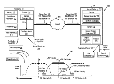
or more bands in a transform domain, such as a discrete Fourier transform
(DFT)
domain. Additionally or alternatively, another set of spatial parameters may
be
estimated in the time domain for one or more sub-frames. Other waveform coding
may
be performed in either the transform domain or the time domain. The mid
channel
signal may correspond to a sum of the first audio signal and the second audio
signal.
Additionally, in stereo-decoding, the mid channel signal and one or more side
channel
signals may be decoded to generate multiple output signals.
[0004] In multichannel encode-decode systems, a DFT transformation may be
performed on audio signals to convert the audio signals from the time domain
to the
transform domain. The DFT transformation may be performed on a portion of an
audio
signal using a window (e.g., an analysis window). The window may include a
look
CA 3014784 2020-01-31
CA 03014784 2018-08-15
WO 2017/161315
PCT[US2017/023035
- 2 -
ahead portion that introduces some delay to the coding process (e.g., encoding
and
decoding). Delays introduced based on the look ahead portions of the encoding
process
and the decoding process contribute to a total amount of delay of the
multichannel
encode-decode system to encode and decode an audio signal.
IV. Summary
[0005] In a particular aspect, a device includes a receiver and a decoder. The
receiver is
configured to receive stereo parameters encoded, by an encoder, based on a
plurality of
windows having a first length of overlapping portions between the plurality of
windows.
The decoder is configured to perform an upmix operation using the stereo
parameters to
generate at least two audio signals. The at least two audio signals are
generated based
on a second plurality of windows used in the upmix operation. The second
plurality of
windows has a second length of overlapping portions between the second
plurality of
windows. The second length is different from the first length.
[0006] In another particular aspect, a method includes receiving stereo
parameters
encoded, by an encoder, based on a plurality of windows having a first length
of
overlapping portions between the plurality of windows. The method further
includes
generating, based on an upmix operation using the stereo parameters, at least
two audio
signals. The at least two audio signals are generated based on a second
plurality of
windows used in the upmix operation. The second plurality of windows has a
second
length of overlapping portions between the second plurality of windows. The
second
length is different from the first length.
[0007] In another particular aspect, an apparatus includes means for receiving
stereo
parameters encoded, by an encoder, based on a plurality of windows having a
first
length of overlapping portions between the plurality of windows. The apparatus
also
includes means for performing an upmix operation using the stereo parameters
to
generate at least two audio signals. The at least two audio signals are
generated based
on a second plurality of windows used in the upmix operation. The second
plurality of
windows has a second length of overlapping portions between the second
plurality of
windows. The second length is different from the first length.
84410572
-3-
100081 In another particular aspect, a computer-readable storage device stores
instructions
that, when executed by a processor, cause the processor to perform operations
including
receiving stereo parameters encoded, by an encoder, based on a plurality of
windows having a
first length of overlapping portions between the plurality of windows. The
operations also
include generating, based on an upmix operation using the stereo parameters,
at least two
audio signals. The at least two audio signals are generated based on a second
plurality of
windows used in the upmix operation. The second plurality of windows has a
second length of
overlapping portions between the second plurality of windows. The second
length is different
from the first length.
[0008a] According to one aspect of the present invention, there is provided an
apparatus
comprising: means for receiving stereo parameters encoded, by an encoder, the
stereo
parameters being encoded using a plurality of windows having a first length of
overlapping
portions between the plurality of windows; and means for performing an upmix
operation
using the stereo parameters to generate at least two audio signals, the at
least two audio
signals generated based on a second plurality of windows used in the upmix
operation, the
second plurality of windows having a second length of overlapping portions
between the
second plurality of windows, the second length different from the first
length.
10008b1 According to another aspect of the present invention, there is
provided a method
comprising: receiving stereo parameters encoded, by an encoder, the stereo
parameters being
encoded using a plurality of windows having a first length of overlapping
portions between
the plurality of windows; and generating, based on an upmix operation using
the stereo
parameters, at least two audio signals, the at least two audio signals
generated based on a
second plurality of windows used in the upmix operation, the second plurality
of windows
having a second length of overlapping portions between the second plurality of
windows, the
second length different from the first length.
[0009] Other aspects, advantages, and features of the present disclosure will
become apparent
after review of the application.
Date Recue/Date Received 2021-06-10
84410572
- 3a -
V. Brief Description of the Drawings
[0010] FIG. 1 a block diagram of a particular illustrative example of a system
that includes an
encoder operable to encode multiple audio signals and a decoder operative to
decode multiple
audio signals;
[0011] FIG. 2 is a diagram illustrating an example of the encoder of FIG. 1;
[0012] FIG. 3 is a diagram illustrating an example of the decoder of FIG. 1;
[0013] FIG. 4 includes a first illustrative example of windows for encoding
and decoding
performed by the system of FIG. 1;
[0014] FIG. 5 includes a second illustrative example of windows for encoding
and decoding
performed by the system of FIG. 1;
[0015] FIG. 6 includes a third illustrative example of windows for encoding
and decoding
performed by the system of FIG. 1;
[0016] FIG. 7 is a flow chart illustrating an example of a method of operating
a coder;
[0017] FIG. 8 is a flow chart illustrating an example of a method of operating
a coder; and
Date Recue/Date Received 2021-06-10
CA 03014784 2018-08-15
WO 2017/161315
PCT[US2017/023035
- 4 -
[0018] FIG. 9 is a block diagram of a particular illustrative example of a
device that is
operable to encode multiple audio signals.
Vi Detailed Description
[0019] Particular aspects of the present disclosure are described below with
reference to
the drawings. In the description, common features are designated by common
reference
numbers. As used herein, various terminology is used for the purpose of
describing
particular implementations only and is not intended to be limiting of
implementations.
For example, the singular forms "a," "an," and "the" are intended to include
the plural
forms as well, unless the context clearly indicates otherwise. It may be
further
understood that the terms "comprise", "comprises", and "comprising" may be
used
interchangeably with "include", "includes", or "including." Additionally, it
will be
understood that the term "wherein" may be used interchangeably with "where."
As
used herein, an ordinal term (e.g., "first," "second,- "third,- etc.) used to
modify an
element, such as a structure, a component, an operation, etc., does not by
itself indicate
any priority or order of the element with respect to another element, but
rather merely
distinguishes the element from another element haying a same name (but for use
of the
ordinal term). As used herein, the term "set- refers to one or more of a
particular
element, and the term "plurality" refers to multiple (e.g., two or more) of a
particular
element.
[0020] In the present disclosure, terms such as "determining", "calculating",
"shifting",
"adjusting", etc. may be used to describe how one or more operations are
performed. It
should be noted that such terms are not to be construed as limiting and other
techniques
may be utilized to perform similar operations. Additionally, as referred to
herein,
"generating", "calculating", "using", "selecting". "accessing". and
"determining" may
be used interchangeably. For example, "generating", "calculating-, or
"determining- a
parameter (or a signal) may refer to actively generating, calculating, or
determining the
parameter (or the signal) or may refer to using, selecting, or accessing the
parameter (or
signal) that is already generated, such as by another component or device.
[0021] In the present disclosure, systems and devices operable to code (e.g.,
encode,
decode, or both) multiple audio signals are disclosed. In some
implementations,
CA 03014784 2018-08-15
WO 2017/161315
PCT/US2017/023035
- 5 -
encoder/decoder windowing may be mismatched for multichannel signal coding to
reduce decoding delay, as described further herein.
[0022] A device may include an encoder configured to encode the multiple audio
signals, a decoder configured to decode multiple audio signals, or both. The
multiple
audio signals may be captured concurrently in time using multiple recording
devices,
e.g., multiple microphones. In some examples, the multiple audio signals (or
multi-
channel audio) may be synthetically (e.g., artificially) generated by
multiplexing several
audio channels that are recorded at the same time or at different times. As
illustrative
examples, the concurrent recording or multiplexing of the audio channels may
result in
a 2-channel configuration (i.e., Stereo: Left and Right), a 5.1 channel
configuration
(Left, Right, Center, Left Surround. Right Surround, and the low frequency
emphasis
(LFE) channels), a 7.1 channel configuration, a 7.1+4 channel configuration, a
22.2
channel configuration, or a N-channel configuration.
[0023] In some systems, an encoder and a decoder may operate as a pair. The
encoder
may perform one or more operations to encode an audio signal and the decoder
may
perform the one or more operations (in a reverse order) to generate a decoded
audio
output. To illustrate, each of the encoder and the decoder may be configured
to perform
a transform operation (e.g., a DFT operation) and an inverse transform
operation (e.g.,
an IDFT operation). For example, the encoder may transform an audio signal
from a
time domain to a transform domain to estimate one or more parameters (e.g.,
Inter
Channel stereo parameters) in transform domain bands, such as DFT bands. The
encoder may also waveform code one or more audio signals based on the
estimated one
or more parameters. As another example, the decoder may transform a
synthesized
audio signal from a time domain to a transform domain prior to application of
one or
more received parameters to the received audio signal.
[0024] Prior to each transform operation and post each inverse transform
operation, a
signal (e.g., an audio signal) is "windowed" to generate windowed samples and
the
windowed samples are used to perform the transform operation or the inverse
transform
operation. In some embodiments, in multichannel coding or stereo coding, the
stereo
downmix operation is performed in the transform domain and the estimated
stereo cue
CA 03014784 2018-08-15
WO 2017/161315
PCT[US2017/023035
- 6 -
parameters are transmitted along with the side and mid channel coded
bitstream. The
mid channel and side channel are encoded for example using ACELP/BWE or TCX
coding after inverse transforming the stereo downmixed mid and side signals.
At the
decoder, the mid and side channel are decoded, windowed, transformed to
frequency
domain followed by stereo upmix processing, inverse transform, and window
overlap
add to generate the multiple-channels (or stereo channels) for rendering. As
used
herein, applying a window to a signal or windowing a signal includes scaling a
portion
of the signal to generate a time-range of samples of the signal. Scaling the
portion may
include multiplying the portion of the signal by values that correspond to a
shape of a
window.
[0025] In some implementations, the encoder and the decoder may implement
different
windowing schemes. A particular windowing scheme implemented by the encoder or
the decoder may be used for DFT analysis (e.g., to perform a DFT transform) or
may be
used for DFT synthesis (e.g., to perform an inverse DFT inverse transform). As
used
herein, a window (or an analysis-synthesis window) is an analysis window, a
synthesis
window, or both an analysis window and a corresponding synthesis window. As an
example of different windowing schemes implemented by the encoder and the
decoder,
the encoder may apply a first window having a first set of characteristics
(e.g., a first set
of parameters) and the decoder may apply a second window having a second set
of
characteristics (e.g., a second set of parameters). One or more
characteristics of the first
set of characteristics may be different from the second set of
characteristics. For
example, the first set of characteristics may differ from the second set of
characteristics
in terms of a size of the window's overlapping portion size (e.g., based on a
look ahead
amount), an amount of zero padding, a window's hop size, a window's center, a
size of
a flat portion of the window, a window's shape, or a combination thereof, as
illustrative,
non-limiting examples. In some implementations, the first window at the
encoder (e.g.,
in multichannel or stereo downmix processing) is configured to generate first
windowed
samples and the second window at the decoder (e.g., in multichannel or stereo
upmix
processing) is configured to generate second windowed samples. The first
windowed
samples and second windowed samples may correspond to different time-frame or
different set of samples that is associated with the encoder delay and the
decoder delay
CA 03014784 2018-08-15
WO 2017/161315
PCT/US2017/023035
- 7 -
of the system. The first windowed samples and the second windowed samples may
have the same DFT bin resolution or may have different DFT bin resolutions.
For
example, the first window at the encoder may be 25ms long resulting in 40 Hz
DFT bin
(frequency) resolution, and the second window at the decoder may be 20ms long
resulting in 50 Hz DFT bin (frequency) resolution. The window may include the
overlap
portion, a flat portion and a zero-padding portion.
[0026] One particular advantage provided by at least one of the disclosed
aspects is that
a coding delay may be reduced. Further, the computational complexity of the
coder
may be significantly reduced. For example, by having the first window and the
second
window be mismatched (e.g., a zero-padding portion or overlapping portion of
the
second window at the decoder may be shorter than a zero-padding portion or
overlapping portion of the first window at the encoder), a delay may be
reduced as
compared to a system where both the encoder and the decoder use the same first
window (with large overlapping portion and zero-padding portion) and are
applied on
samples corresponding to the same time-range of samples.
[0027] Referring to FIG. 1, a particular illustrative example of a system 100
is depicted.
The system 100 includes a first device 104 communicatively coupled, via a
network
120, to a second device 106. The network 120 may include one or more wireless
networks, one or more wired networks, or a combination thereof
[0028] The first device 104 may include an encoder 114, a transmitter 110, one
or more
input interfaces 112, or a combination thereof A first input interface of the
input
interface(s) 112 may be coupled to a first microphone 146. A second input
interface of
the input interface(s) 112 may be coupled to a second microphone 148. The
encoder
114 may include a sample generator 108 and a transform device 109 and may be
configured to encode multiple audio signals, as described herein.
[0029] The first device 104 may also include a memory 153 configured to store
first
window parameters 152. The first window parameters 152 may define a first
window or
a first windowing scheme to be applied by the sample generator 108 to at least
a portion
of an audio signal, such as the first audio signal 130 or the second audio
signal 132. For
example, the sample generator 108 may apply a first window (based on the first
window
CA 03014784 2018-08-15
WO 2017/161315
PCT/US2017/023035
- 8 -
parameters 152) to at least a portion of an audio signal to generate windowed
samples
111 that are provided to the transform device 109. The transform device 109
may be
configured to perform a transform operation, such as a transform operation
(e.g., a DFT
operation) or an inverse transform operation (e.g., an IDFT operation), on the
windowed
samples.
[0030] An example of a windowing scheme 190 includes multiple windows, such as
a
first window (n-1) 192, a second window (n) 191, and a third window (n+1) 193,
where
n is an integer. Although the windowing scheme 190 is described as having
three
windows, in other implementations, the windowing scheme may include more than
or
fewer than three windows.
[0031] Referring to the second window (n) 191, the second window (n) 191
includes
zero padding portions 194, 196, a window center 195, and a flat portion 198.
The zero
padding portions 194, 196 may be included in the second window (n) 191, for
example,
to control a total length (e.g., a duration) of the second window (n) 191. The
flat
portion 198 may correspond to, for example, a scaling factor of 1. The second
window
(n) 191 may also include multiple overlapping portions, such as a
representative
overlapping portion 199. A hop size 197 may indicate an offset of the second
window
(n) 191 with respect to the first window (n-1) 192. The hop size between any
two
consecutive windows of the windowing scheme 190 may be the same.
[0032] The second device 106 may include a decoder 118, a memory 175, a
receiver
178, one or more output interfaces 177, or a combination thereof The receiver
178 of
the second device 106 may receive an encoded audio signal (e.g., one or more
bit
streams), one or more parameters, or both from the first device 104 via the
network 120.
The decoder 118 may include a sample generator 172 and a transform device 174,
and
may be configured to render the multiple channels. The second device 106 may
be
coupled to a first loudspeaker 142, a second loudspeaker 144, or both.
[0033] The memory 175 may be configured to store second window parameters 176.
The second window parameters 176 may define a second window or a second
windowing scheme to be applied by the sample generator 172 to at least a
portion of an
audio signal, such as an encoded audio signal (e.g., the side bitstream 164,
the mid
CA 03014784 2018-08-15
WO 2017/161315
PCT/US2017/023035
- 9 -
bitstream 166, or both). For example, the sample generator 172 may apply a
second
window (based on the second window parameters 176) to at least a portion of an
encoded audio signal to generate windowed samples that are provided to the
transform
device 174. The transform device 174 may be configured to perform a transform
operation, such as a transform operation (e.g., a DFT operation) or an inverse
transform
operation (e.g., an IDFT operation), on the windowed samples.
[0034] The first window parameters 152 (of the first device 104) used by the
encoder
114 and the second window parameters 176 (of the second device 106) used by
the
decoder 118 may be mismatched. For example, the first window (defined by the
first
window parameters 152) may differ from the second window (defined by the
second
window parameters 176) in terms of a size of the window's overlapping portion
size
(e.g., based on a look ahead amount), an amount of zero padding, a window's
hop size,
a window's center, a size of a fiat portion of the window, a window's shape,
or a
combination thereof, as illustrative, non-limiting examples. In some
implementations,
the first window at the encoder 114 (e.g., in multichannel or stereo downmix
processing) is configured to generate first windowed samples and the second
window at
the decoder 118 (e.g., in multichannel or stereo upmix processing) is
configured to
generate second windowed samples. In some implementations, the first window is
used
by the encoder 114 to generate first windowed samples and the second window is
used
by the decoder 118 to generate second windowed samples. The first windowed
samples
and the second windowed samples may have the same DFT bin (or frequency)
resolution or may have different DFT bin resolutions.
[0035] During operation, the first device 104 may receive a first audio signal
130 via
the first input interface from the first microphone 146 and may receive a
second audio
signal 132 via the second input interface from the second microphone 148. The
first
audio signal 130 may correspond to one of a right channel signal or a left
channel
signal. The second audio signal 132 may correspond to the other of the right
channel
signal or the left channel signal. In some implementations, a sound source 152
(e.g., a
user, a speaker, ambient noise, a musical instrument, etc.) may be closer to
the first
microphone 146 than to the second microphone 148. Accordingly, an audio signal
from
the sound source 152 may be received at the input interface(s) 112 via the
first
CA 03014784 2018-08-15
WO 2017/161315
PCT/US2017/023035
- 10 -
microphone 146 at an earlier time than via the second microphone 148. This
natural
delay in the multi-channel signal acquisition through the multiple microphones
may
introduce a temporal shift between the first audio signal 130 and the second
audio signal
132. In some implementations, the encoder 114 may be configured to adjust
(e.g., shift)
at least one of the first audio signal 130 or the second audio signal 132 to
temporally
align the first audio signal 130 and the second audio signal 132 in time. For
example,
the encoder 118 may shift a first frame (of the first audio signal 130) with
respect to a
second frame (of the second audio signal 132).
[0036] The sample generator 108 may apply a first window (based on the first
window
parameters 152) to at least a portion of an audio signal to generate windowed
samples
111 that are provided to the transform device 109. The windowed samples 111
may be
generated in a time-domain. The transform device 109 (e.g., a frequency-domain
stereo
coder) may transform one or more time-domain signals, such as the windowed
samples
(e.g., the first audio signal 130 and the second audio signal 132), into
frequency-domain
signals. The frequency-domain signals may be used to estimate stereo cues 162.
The
stereo cues 162 may include parameters that enable rendering of spatial
properties
associated with left channels and right channels. According to some
implementations,
the stereo cues 162 may include parameters such as interchannel intensity
difference
(HD) parameters (e.g., interchannel level differences (1LDs), interchannel
time
difference (ITD) parameters, interchannel phase difference (IPD) parameters,
interchannel correlation (ICC) parameters, stereo filling parameters, non-
causal shift
parameters, spectral tilt parameters, inter-channel voicing parameters, inter-
channel
pitch parameters, inter-channel gain parameters, etc., as illustrative, non-
limiting
examples). The stereo cues 162 may be used at the frequency domain stereo
coder 109
during the stereo downmix processing. The stereo cues 162 may also be
transmitted as
part of an encoded signal. Estimation and use of the stereo cues 162 is
described in
greater detail with respect to FIG. 2.
[0037] The encoder 114 may also generate a side bitstream 164 and a mid
bitstream 166
based at least in part on the frequency-domain signals. For purposes of
illustration,
unless otherwise noted, it is assumed that that the first audio signal 130 is
a left-channel
signal (1 or L) and the second signal 132 is a right-channel signal (r or R).
The
CA 03014784 2018-08-15
WO 2017/161315
PCT/US2017/023035
- 11 -
frequency-domain representation of the first audio signal 130 may be noted as
Lfi-(b)
and the frequency-domain representation of the second audio signal 132 may be
noted
as Rfr(b), where b represents a frequency band of the frequency bin. According
to one
implementation, a side signal Sfr(b) may be generated in the frequency-domain
from
frequency-domain representations of the first audio signal 130 and the second
audio
signal 132. For example, the side signal Sfr(b) may be expressed as (Lfr(b)-
Rfr(b))/2.
The side signal Sfr(b) may be provided to a "side or residual" encoder to
generate the
side bitstream 164. According to one implementation, a mid signal Mfr(b) may
be
generated in the frequency-domain from frequency-domain representations of the
first
audio signal 130 and the second audio signal 132. According to one
implementation, a
mid signal Mfr(b) may be generated in the frequency-domain and transformed
into the
frequency-domain a mid signal m(t). According to another implementation, a mid
signal m(t) may be generated in the time-domain and transformed into the
frequency-
domain. For example, the mid signal m(t) may be expressed as (1(0+40)/2.
Generating
the mid signal and the side signal is described in greater detail with respect
to FIG. 2.
The time-domain/frequency-domain mid signals may be provided to a mid signal
encoder to generate the mid bitstream 166.
[0038] The side signal Sfr(b) and the mid signal m(t) or Mfr(b) may be encoded
using
multiple techniques. According to one implementation, the time-domain mid
signal
m(t) may be encoded using a time-domain technique, such as algebraic code-
excited
linear prediction (ACELP), with a bandwidth extension for high-band coding.
[0039] One implementation of side coding includes predicting a side signal
SpRED(b)
from the frequency-domain mid signal Mfr(b) using the information in the
frequency
mid signal Mfr(b) and the stereo cues 162 (e.g., ILDs) corresponding to the
band (b).
For example, the predicted side signal SPRED(b) may be expressed as
Mfr(b)*(ILD(b)-
CA 03014784 2018-08-15
WO 2017/161315
PCT/US2017/023035
- 12 -
1)/(ILD(b)+1). An error signal (or a residual signal) e(b) in the band (b) may
be
calculated as a function of the side signal Sfr(b) and the predicted side
signal SpRED(b).
For example, the error signal e(b) may be expressed as Sfr(b)-SPRED(b). The
error
signal e(b) may be coded using transform-domain coding techniques to generate
a coded
error signal ecODED(b). For upper-bands, the error signal e(b) may be
expressed as a
scaled version of a mid signal M_PASTfr(b) in the band (b) from a previous
frame. For
example, the coded error signal ecoDED(b) may be expressed as
gPRED(b)*M_PASTfi-(b), where, in some implementations, gPRED(b) may be
estimated such that an energy of e(b)-gpRED(b)* M_PASTfr(b) is substantially
reduced
(e g , minimized) The gPRED(b) values may he alternatively referred to as
stereo
filling gains.
[0040] The transmitter 110 may transmit the stereo cues 162, the side
bitstream 164, the
mid bitstream 166, or a combination thereof, via the network 120, to the
second device
106. Alternatively, or in addition, the transmitter 110 may store the stereo
cues 162, the
side bitstream 164, the mid bitstream 166, or a combination thereof, at a
device of the
network 120 or a local device for further processing or decoding later.
[0041] The decoder 118 may perform decoding operations based on the stereo
cues 162,
the side bitstream 164, and the mid bitstream 166. The sample generator 172
may apply
a second window (based on the second window parameters 176) to at least a
portion of a
received encoded (e.g., a synthesized mid signal or side signal) signal (e.g.,
based on the
side bitstream 164, the mid bitstream 166, or both) to generate windowed
samples that
are provided to the transform device 174. The windowed samples may be
generated in
a time-domain. The transform device 174 (e.g., a frequency-domain stereo
coder) may
transform one or more time-domain signals, such as the windowed samples (e.g.,
the
side bitstream 164, the mid bitstream 166, or both), into frequency-domain
signals. The
stereo cues 162 may be applied to the frequency-domain signals.
[0042] By applying the stereo cues 162, the decoder 118 may perform the stereo
upmix
CA 03014784 2018-08-15
WO 2017/161315
PCT/US2017/023035
- 13 -
process and generate a first output signal 126 (e.g., corresponding to first
audio signal
130), a second output signal 128 (e.g., corresponding to the second audio
signal 132), or
both. The second device 106 may output the first output signal 126 via the
first
loudspeaker 142. The second device 106 may output the second output signal 128
via
the second loudspeaker 144. In alternative examples, the first output signal
126 and
second output signal 128 may be transmitted as a stereo signal pair to a
single output
loudspeaker.
[0043] Although the first device 104 and the second device 106 have been
described as
separate devices, in other implementations, the first device 104 may include
one or more
components described with reference to the second device 106. Additionally or
alternatively, the second device 106 may include one or more components
described
with reference to the first device 104. For example, a single device may
include the
encoder 114, the decoder 118, the transmitter 110, the receiver 178, the one
or more
input interfaces 112, the one or more output interfaces 177, and a memory. The
memory of the single device may include the first window parameters 152 that
define a
first window to be applied by the encoder 114 and the second window parameters
176
that define a second window to be applied by the decoder 176.
[0044] In a particular implementation, the second device 106 includes the
receiver 178
configured to receive stereo parameters (e.g., the stereo cues 162) encoded,
by the
encoder 114 (of the first device 104), based on a plurality of windows (e.g.,
a particular
windowing scheme) having a first length of overlapping portions between the
plurality
of windows. The receiver 178 may also be configured to receive a mid signal,
such as
the mid bitstream 166 generated by the encoder 114 based on a downmix
operation
using the stereo parameters (e.g., the stereo cues 162) as described with
reference to
FIG. 2.
[0045] The second device 106 further includes the decoder 118 configured to
perform
an upmix operation, as described further with reference to FIG. 3, using the
stereo
parameters to generate at least two audio signals, such as the first output
signal 126 and
the second output signal 128. The second plurality of windows is configured to
produce
decoding delay that is less than a window overlap corresponding to the
plurality of
CA 03014784 2018-08-15
WO 2017/161315
PCT[US2017/023035
- 14 -
windows. In other words, the inter-frame overlap of the second plurality of
windows at
the decoder is smaller than the plurality of windows at the corresponding
encoder. The
at least two audio signals are generated based on a second plurality of
windows having a
second length of overlapping portions between the second plurality of windows.
The
second length is different from the first length. For example, the second
length is less
than the first length. In some implementations, the upmix operation is
performed using
the stereo parameters and the mid signal. In some implementations, the
receiver is
configured to receive an audio signal that includes the stereo parameters, and
the
decoder 118 is configured to apply the second plurality of windows during
decoding of
the audio signal to generate a windowed time-domain audio decoding signal.
[0046] In some implementations, a total length of each window the plurality of
windows used by the encoder 114 is different from the total length of each
window of
the second plurality of windows used by the decoder 118. Additionally or
alternatively,
a first frequency width associated with each frequency bin in a transform
domain at the
encoder 114 is different from a second frequency width associated with each
frequency
bin in the transform domain at the decoder 118.
[0047] In some implementations, the plurality of windows is associated with a
first hop
length and the second plurality of windows is associated with a second hop
length. The
first hop length is different from the second hop length. Additionally or
alternatively,
the plurality of windows may include a different number of windows than the
second
plurality of windows per each frame of audio data. In some implementations, a
first
window of the plurality of windows and a second window of the second plurality
of
windows are the same size. In a particular implementation, each window of the
plurality of windows is symmetric and a first particular window of the second
plurality
of windows is asymmetric (e.g., individually or with respect to a second
particular
window of the second plurality of windows).
[0048] In some implementations, a window overlap of the second plurality of
windows
is asymmetric. Additionally or alternatively, a first window of a pair of
consecutive
windows of the second plurality of windows is asymmetric. A third length of a
first
overlap portion of the first window and the second window is different from a
fourth
CA 03014784 2018-08-15
WO 2017/161315
PCT[US2017/023035
- 15 -
length of a second overlap portion of the second window and a third window of
a
second pair of consecutive windows. In other implementations, both windows of
a pair
of consecutive windows of the second plurality of windows are symmetric.
[0049] In some implementations, the second device 106 includes an encoder that
is
configured to apply the plurality of windows during encoding of a second audio
signal
to generate a windowed time-domain audio encoding signal. The second device
106
may further includes a transmitter configured to transmit an output bit stream
(e.g., an
output audio signal) generated based on the windowed time-domain audio
encoding
signal.
[0050] The system 100 may thus enable reduced coding delay. For example, by
having
the first window (applied by the encoder 114) and the second window (applied
by the
decoder 118) be mismatched (e.g., an overlapping portion of the second window
of a
decoder may be shorter than an overlapping portion of the first window of an
encoder),
a delay may be reduced as compared to a system where the encoder and the
decoder
transform windows match exactly and are applied on samples corresponding to
the same
time-range of samples.
[0051] Referring to FIG. 2, a diagram illustrating a particular implementation
of the
encoder 114 is shown. A first signal 290 and a second signal 292 may
correspond to a
left-channel signal and a right-channel signal. In some implementations, one
of the left-
channel signal or the right-channel signal (the "target" signal) has been time-
shifted
relative to the other of the left-channel signal or the right-channel signal
(the "reference"
signal) to increase coding efficiency (e.g., to reduce side signal energy). In
some
examples, a first signal or the reference signal 290 may include a windowed
left-channel
signal, and a second signal or the target signal 292 may include a windowed
right-
channel signal The window may he based on the first window parameters 152.
However, it should be understood that in other examples, the reference signal
290 may
include a windowed right-channel signal and the target signal 292 may include
a
windowed left-channel signal. In other implementations, the reference channel
290 may
be either of the left or the right windowed channel which is chosen on a frame-
by-frame
basis and similarly, the target signal 292 may be the other of the left or
right windowed
CA 03014784 2018-08-15
WO 2017/161315
PCT/US2017/023035
- 16 -
channels. For the purposes of the descriptions below, an example is provided
of the
specific case when the reference signal 290 includes a windowed left-channel
signal (L)
and the target signal 292 includes a windowed right-channel signal (R).
Similar
descriptions for the other cases can be trivially extended. It is also to be
understood that
the various components illustrated in FIG. 2 (e.g., transforms, signal
generators,
encoders, estimators, etc.) may be implemented using hardware (e.g., dedicated
circuitry), software (e.g., instructions executed by a processor), or a
combination
thereof
[0052] A transform 202 may be performed on the reference signal 290 (or the
left
channel) and a transform 204 may be performed on the target signal 292 (or the
right
channel). The transforms 202, 204 may be performed by transform operations
that
generate frequency-domain (or sub-band domain or filtered low-band core and
high-
band bandwidth extension) signals. As non-limiting examples, performing the
transforms 202, 204 may performing include Discrete Fourier Transform (DFT)
operations, Fast Fourier Transform (FFT) operations, modified discrete cosine
transform (MDCT), etc. on the windowed left channel 290 and the windowed right
channel 292. In some other implementations, the windowing based on the first
window
parameters 152 may be part of the transform device 109 and may be part of the
transform 202, 204. According to some implementations, Quadrature Mirror
Filterbank
(QMF) operations (using filterbands, such as a Complex Low Delay Filter Bank)
may
be used to split the input signals (e.g., the reference signal 290 and the
target signal 292)
into multiple sub-bands, and the sub-bands may be converted into the frequency-
domain
using another frequency-domain transform operation. The transform 202 may be
applied to the reference signal 290 to generate a frequency-domain reference
signal
(Lfr(b)) 230, and the transform 204 may be applied to the target signal 292 to
generate a
frequency-domain target signal (Rfr(b)) 232. The transform 202, 204 operation
may
include windowing operation based on the first window parameters 152. The
frequency-domain reference signal 230 and the frequency-domain target signal
232 may
be provided to a stereo cue estimator 206 and to a side signal generator 208.
[0053] The stereo cue estimator 206 may extract (e.g., generate) the stereo
cues 162
CA 03014784 2018-08-15
WO 2017/161315
PCT/US2017/023035
- 17 -
based on the frequency-domain reference signal 230 and the frequency-domain
target
signal 232. To illustrate, IID(b) may be a function of the energies EL(b) of
the left
channels in the band (b) and the energies ER(b) of the right channels in the
band (b).
For example, IID(b) may be expressed as 20*10gto(EL(b)/ ER(b)). IPDs estimated
and transmitted at an encoder may provide an estimate of the phase difference
in the
frequency-domain between the left and right channels in the band (b). The
stereo cues
162 may include additional (or alternative) parameters, such as ICCs, ITDs
etc. The
stereo cues 162 may be transmitted to the second device 106 of FIG. 1,
provided to the
side signal generator 208, and provided to a side signal encoder 210. In some
implementations, at least one parameter of the stereo parameters is
interpolated inter-
frame, and the at least one interpolated parameter or at least one un-
interpolated value
(of the stereo parameters) are sent to and used by the decoder, such as the
decoder 118
of FIG. 1. For example, the interpolation can be performed at the encoder and
the at
least one interpolated parameter can be sent to the decoder. Alternatively,
the stereo
parameters are sent from the encoder to the decoder and the decoder performs
the inter-
frame interpolation to generate the at least one interpolated parameter.
[0054] The side signal generator 208 may generate a frequency-domain side
signal
(Sfr(b)) 234 based on the frequency-domain reference signal 230 and the
frequency-
domain target signal 232. The frequency-domain side signal 234 may be
estimated in
the frequency-domain bins/bands. In each band, the gain parameter (g) may be
different
and may be based on the interchannel level differences (e.g., based on the
stereo cues
162). For example, the frequency-domain side signal 234 may be expressed as
(Lfr(b) ¨
c(b)* Rfr(b))/(1+c(b)), where c(b) may be the ILD(b) or a function of the
ILD(b) (e.g.,
c(b) = 10^(ILD(b)/20)). The frequency-domain side signal 234 may be provided
to an
inverse transform 250. For example, the frequency-domain side signal 234 may
be
inverse-transformed back to time domain to generate a time-domain side signal
S(t) 235,
or transformed to MDCT domain, for coding. The time-domain side signal 235 may
be
provided to the side signal encoder 210.
[0055] The frequency-domain reference signal 230 and the frequency-domain
target
CA 03014784 2018-08-15
WO 2017/161315
PCT/US2017/023035
- 18 -
signal 232 may be provided to a mid signal generator 212. According to some
implementations, the stereo cues 162 may also be provided to the mid signal
generator
212. The mid signal generator 212 may generate a frequency-domain mid signal
Mfr(b)
238 based on the frequency-domain reference signal 230 and the frequency-
domain
target signal 232. According to some implementations, the frequency-domain mid
signal Mfr(b) 238 may be generated also based on the stereo cues 162. Some
methods
of generation of the mid signal 238 based on the frequency domain reference
channel
230, the target channel 232 and the stereo cues 162 are as follows.
[0056] Mfr(b)= (Lfr(b)+ Rfr(b))/2
[0057] Mfr(b)= Ci(b)*Lfr(b)+ C2*Rfr(b), where Ci(b) and C2(b) are complex
values.
[0058] In some implementations, the complex values Ci(b) and C2(b) are based
on the
stereo cues 162. For example, in one implementation of mid side downmix when
IPDs
are estimated, Ci(b) = (cos(-y) - i*sin(_y))/2" and C2(b) = (cos(IPD(b)-y) +
i*sin(IPD(b)-y))/2 .5 where i is the imaginary number signifying the square
root of -I.
[0059] The frequency-domain mid signal 238 may be provided to an inverse
transform
252. For example, the frequency-domain mid signal 238 may be inverse-
transformed to
time domain to generate a time-domain mid signal 236, or transformed to MDCT
domain, for coding. After the inverse transform 252, the mid signal may be
windowed
and overlap added with the previous frame's windowed mid signal overlapping
portion.
This window may be similar to or different than the window used in transform
202, 204.
The time-domain mid signal 236 may be provided to a mid signal encoder 216,
and the
frequency-domain mid signal 238 may be provided to the side signal encoder 210
for
the purpose of efficient side band signal encoding.
[0060] The side signal encoder 210 may generate the side bitstream 164 based
on the
stereo cues 162, the time-domain side signal 235, and the frequency-domain mid
signal
238. The mid signal encoder 216 may generate the mid bitstream 166 based on
the
CA 03014784 2018-08-15
WO 2017/161315
PCT/US2017/023035
- 19 -
time-domain mid signal 236. For example, the mid signal encoder 216 may encode
the
time-domain mid signal 236 to generate the mid bitstream 166.
[0061] The transforms 202 and 204 may be configured to apply an analysis
windowing
scheme associated with the first window parameters 152 of FIG. 1. For example,
the
stereo cue parameters 162 may include parameter values computed based on the
windowed samples I 1 I of FIG. 1. Additionally, the inverse transforms 250,
252 may be
configured to perform inverse transforms followed by synthesis windowing
(generated
using a windowing scheme associate with the first window parameters 152 of
FIG. 1) to
return frequency-domain signals to overlapping windowed time-domain signals.
[0062] In some implementations, one or more of the stereo cue estimator 206,
the side
signal generator 208, and the mid signal generator 212 may be included in a
downmixer.
Additionally or alternatively, although the encoder 114 is described as
including the
side signal encoder 210, in other implementations the encoder 114 may not
include the
side signal encoder 210.
[0063] Referring to FIG. 3, a diagram illustrating a particular implementation
of the
decoder 118 is shown. An encoded audio signal is provided to a demultiplexer
(DEMUX) 302 of the decoder 118. The encoded audio signal may include the
stereo
cues 162, the side bitstream 164, and the mid bitstream 166. The demultiplexer
302
may be configured to extract the mid bitstream 166 from the encoded audio
signal and
provide the mid bitstream 166 to a mid signal decoder 304. The demultiplexer
302 may
also be configured to extract the side bitstream 164 and the stereo cues 162
from the
encoded audio signal. The side bitstream 164 and the stereo cues 162 may be
provided
to a side signal decoder 306.
[0064] The mid signal decoder 304 may be configured to decode the mid
bitstream 166
to generate a mid signal (incoDED(0) 350. A transform 308 may be applied to
the mid
signal 350 to generate a frequency-domain mid signal (McoDED(b)) 352. The
frequency-domain mid signal 352 may be provided to an up-mixer 310.
[0065] The side signal decoder 306 may generate a side signal (ScoDED(b)) 354
based
on the side bitstream 164, the stereo cues 162, and the frequency-domain mid
signal
CA 03014784 2018-08-15
WO 2017/161315
PCT/US2017/023035
- 20 -
352. For example, the error (e) may be decoded for the low-bands and the high-
bands.
The side signal 354 may be expressed as SPRED(b) + ecoDED(b), where SPRED(b) =
McoDED(b)*(ILD(b)-1)/(ILD(b)+1). A transform 309 may be applied to the side
signal
354 to generate a frequency-domain side signal (ScoDED(b)) 355. The frequency-
domain side signal 355 may also be provided to the up-mixer 310.
[0066] The up-mixer 310 may perform an up-mix operation based on the frequency-
domain mid signal 352 and the frequency-domain side signal 355. For example,
the up-
mixer 310 may generate a first up-mixed signal (Lfr) 356 and a second up-mixed
signal
(Rfr) 358 based on the frequency-domain mid signal 352 and frequency-domain
the side
signal 355. Thus, in the described example, the first up-mixed signal 356 may
be a left-
channel signal, and the second up-mixed signal 358 may be a right-channel
signal. The
first up-mixed signal 356 may be expressed as McoDED(b)+ScoDED(b), and the
second
up-mixed signal 358 may be expressed as McoDEDN-ScoDED(b). The up-mixed
signals 356, 358 may be provided to a stereo cue processor 312.
[0067] The stereo cue processor 312 may apply the stereo cues 162 to the up-
mixed
signals 356, 358 to generate signals 360, 362. For example, the stereo cues
162 may be
applied to the up-mixed left and right channels in the frequency-domain. When
available, the IPD (phase differences) may be spread on the left and right
channels to
maintain the interchannel phase differences. An inverse transform 314 may be
applied
to the signal 360 to generate a first time-domain signal 1(t) 364 (e.g., a
left channel
signal), and an inverse transform 316 may be applied to the signal 362 to
generate a
second time-domain signal r(t) 366 (e.g., a right channel signal). Non-
limiting
examples of the inverse transforms 314, 316 include Inverse Discrete Cosine
Transform
(IDCT) operations, Inverse Fast Fourier Transform (IFFT) operations, etc.
According
to one implementation, the first time-domain signal 364 may be a reconstructed
version
of the reference signal 290, and the second time-domain signal 366 may be a
reconstructed version of the target signal 292.
[0068] According to one implementation, the operations performed at the up-
mixer 310
CA 03014784 2018-08-15
WO 2017/161315
PCT[US2017/023035
- 21 -
may be performed at the stereo cue processor 312. According to another
implementation, the operations performed at the stereo cue processor 312 may
be
performed at the up-mixer 310. According to yet another implementation, the up-
mixer
310 and the stereo cue processor 312 may be implemented within a single
processing
element (e.g., a single processor).
[0069] The transforms 308 and 309 may be configured to apply an analysis
windowing
scheme associated with the second window parameters 176 of FIG. 1. The second
windowing parameters 176 associated with the windowing scheme used by the
transforms 308 and 309 may be different from a windowing scheme used by an
encoder,
such as the encoder 114 of FIG. 1. The second windowing scheme may be used at
the
transforms 308, 309 to reduce delay in decoding. For example, a second
windowing
scheme (applied by the decoder) may include windows having a different size as
the
windows used in a first windowing scheme (applied by an encoder) such that the
transform may result in same number of frequency bands (but different
frequency
resolution), and further the amount of window overlap may be reduced for the
transforms 308 and 309. Reducing the amount of window overlap reduces a
decoding
delay of processing overlapped samples from a prior window. Because the stereo
cues
may be generated based on the first windowing (applied by the encoder 114),
the
decoder 118 may generate adjusted stereo parameters to account for differences
in the
windowing schemes. For example, the decoder 114 (e.g., the stereo cue
processor 312)
may generate adjusted stereo parameters via interpolation (e.g., weighted
sums) of the
received stereo parameters. Similarly, the inverse transforms 314, 316 may be
configured to perform inverse transforms to return frequency-domain signals to
overlapping windowed time-domain signals.
[0070] In some implementations, the stereo cue processor 312 may be included
in the
up-mixer 310. Additionally, or alternatively, although the decoder 118 is
described as
including the side signal decoder 306 and the transform 309, in other
implementations
the decoder 118 may not include the side signal decoder 306 and the transform
309. In
such implementations, the side bitstream 164 may be provided from the
demultiplexer
302 to the up-mixer 310 and the stereo cues 162 may be provided from the
demultiplexer 302 to the up-mixer 310 or to the stereo cue processor 312.
CA 03014784 2018-08-15
WO 2017/161315
PCT[US2017/023035
- 22 -
[0071] Ills noted that the encoder of FIG. 2 and the decoder of FIG. 3 may
include a
portion, but not all, of an encoder or decoder framework. For example, the
encoder of
FIG. 2, the decoder of FIG. 3, or both, may also include a parallel path of
high-band
(HB) processing. Additionally or alternatively, in some implementations, a
time
domain downmix may be performed at the encoder of FIG. 2. Additionally or
alternatively, a time domain upmix may follow the decoder of FIG. 3 to obtain
decoder
shift compensated Left and Right channels.
[0072] Referring to FIG. 4, an example of windowing schemes implemented at an
encoder and decoder is depicted. For example, a windowing scheme implemented
by a
decoder, such as the decoder 118 of FIG. 1, is depicted and generally
designated 400.
In some implementations, the windowing scheme 400 may be implemented based on
the second window parameters 176. A windowing scheme implemented by an
encoder,
such as the encoder 114 of FIG. 1, is depicted and generally designated 450.
In some
implementations, the windowing scheme 450 may be implemented based on the
first
window parameters 152. With reference to the windowing scheme 400 and the
windowing scheme 450, each window is the same. To illustrate, each window has
the
same zero padding length, the same hop size, the same overlap, and the same
flat
portion size. For example, the zero padding length is 3.125 ms, the window hop
size is
ms, the window's overlap length is 8.75 ms, and the size of the flat portion
of the
window is 1.25 ms. Accordingly, each window may have a total length of 25 ms.
[0073] A frame size of an audio signal may be 20 ms and transform operations,
such as
DFT operations, may be estimated in 2 windows per frame. For each frame, a set
of
stereo cue parameters (e.g., DFT stereo cue parameters), such as the stereo
cues 162 of
FIG. 1, may be quantized and transmitted. These stereo cues are also used to
generate
the mid and the side signals in the transform domain as described with
reference to
FIGs. 1 and 2 (described above) and as described with reference to Equations 1
and 2
(included below). For example, the Mid channel may be based on:
M = (L+gDR)/2, or Equation 1
M = giL + g2R Equation 2
CA 03014784 2018-08-15
WO 2017/161315
PCT[US2017/023035
- 23 -
where gi + g2 = 1.0, and where gp is a gain parameter, M corresponds to the
Mid
channel. L corresponds to the left channel, and R corresponds to the right
channel.
[0074] Prior to coding, the frame corresponding to [0-28.75] of mid and side
is
synthesized by applying the inverse transforms on the transform domain mid and
side
signals. After the inverse transforms, the time domain signals are overlap-
added with a
similar window as above. In some implementations, the window could be exactly
the
same, in others, this transform window and the inverse transform window could
have
different window values in the overlapping regions while keeping the lengths
of the zero
padding, overlap, and the flat portion size all the same. The overlap-add is
used on the
inverse transform synthesis because the overlapping windows will produce two
sets of
time samples in the overlap portion. For example, an inverse transform on
wo(n) (e.g., a
first window of frame n) produces the samples from [0-18.75] ms, while an
inverse
transform produces samples from [10-28.75] ms. The samples from 110-18.75] are
overlap added to produce the mid and the side signals for the portion of [0-
28.75] ms.
Since there is no overlapping window (wo(n+1)) (e.g., a first window of frame
n+1)
present from the [20-38.75] ms yet on the encoder (as samples after 28.75 are
in the
future not available in the current frame n), the samples generated from the
inverse
transform of wi(n) (e.g., a second window of frame n) are un-windowed and used
for
coding in the portion of [20-28.75] ms. Unwindowing means that the samples
generated from the IDFT are divided by wi(n) in that portion.
[0075] It should be noted that the samples from [20-28.75] on the encoder are
part of
the mid/side coding look ahead in frame n. On the decoder, these samples may
be
intended to be decoded in the frame n+1.
[0076] On the decoder, we receive the bitstream, first decode the mid and side
signals
may be received into time domain from the portion [0-20] ms if a speech
decoder, such
as an ACELP decoder, is used and [0-28.75] ms if a non-speech decoder, such as
a TCX
decoder, is used. If the non-speech decoder is used, the samples from [20-
28.75] may
not be used/played out in the current frame, but are stored for overlap add in
the next
frame which has the effect of producing a usable set of samples from [0-20]
ms. Since
samples from [20-28.75] are not available at the decoder, a delay of the
window hop
CA 03014784 2018-08-15
WO 2017/161315
PCT/US2017/023035
- 24 -
size is introduced to look back in time and use [-10 to 18.751 ms for
windowing and
application of the stereo parameters. Once this windowing is performed on the
decoded
mid/side signals, the upmix is performed followed by stereo parameter
application to
get the decoded DFT domain representation of the left and the right channels.
An
inverse DFT is applied followed by an overlap-add operation to obtain the
decoded left
and right time domain signals.
[0077] As depicted in FIG. 4, the encoder windows (of the windowing scheme
450) and
the decoder windows (of the windowing scheme 400) have the same
characteristics.
For example, the encoder windows (of the windowing scheme 450) and the decoder
windows (of the windowing scheme 400) have the same sizes, the same amount of
overlap, the same zero padding, the same size flat portions, etc. Due to the
encoder
window and the decoder window match, a delay of 10 ms introduced on the
decoder in
addition to 28.75 ills delay introduced on the encoder.
[0078] It is noted that the windowing scheme 450 of the encoder and the
windowing
scheme 400 of the decoder are applied at the exact same time samples. For
example, as
depicted in FIG. 4, the decoder windows and the encoder windows are the same
and are
situated at the same time range. Thus, the window centers are aligned on the
encoder
and the decoder. Alternatively, in other implementations, the windows used by
the
encoder and the windows used by the decoder may not be aligned. For example, a
window location (e.g., a window center) of each window of the plurality of
windows
used by the encoder is different from a window location (e.g., a window
center) of each
window of the plurality of windows used at the decoder.
[0079] Referring to FIG. 5, another example of windowing schemes implemented
at an
encoder and decoder is depicted. For example, a windowing scheme implemented
by a
decoder, such as the decoder 118 of FIG. 1, is depicted and generally
designated 510.
In some implementations, the windowing scheme 510 may be implemented based on
the second window parameters 176. A windowing scheme implemented by an
encoder,
such as the encoder 114 of FIG. 1, is depicted and generally designated 520.
In some
implementations, the windowing scheme 520 may be implemented based on the
first
window parameters 152.
CA 03014784 2018-08-15
WO 2017/161315
PCT[US2017/023035
- 25 -
[0080] The windowing scheme 510 may have a single window per frame (a hop size
of
20 ms) and an overlap region of 3.25 ms. Accordingly, the decoder delay is
3.25 ms.
The zero padding (zp) length is of the windowing scheme 510 is 0.875 ms on
both sides
of the window and a length of the flat portion is 16.75 ms. The total length
(L) of the
window of the windowing scheme 510 may be determined as L = 2*zp + 2*overlap +
flat_portion = 25 ms. The length of the overlapping portions + the flat
portion together
constitute the actual amount of samples used. The zero padding is used to
bring the
window to a desired size. In another implementation, the windowing scheme 510
may
use two windows with an outer overlap of e.g., 3.125ms while the inner overlap
of e.g.,
ms.
[0081] The windowing scheme 520 may include or correspond to the windowing
scheme 450 of FIG. 4. It is noted that the total length of each window of the
windowing
scheme 520 used on the encoder is the same as the total the windowing scheme
510
used on the decoder. By having the same total length, the size of the DFT bins
generated by the encoder and the decoder may match. It should be noted that
matching
the total length of the size of the windows is considered a matter of
convenience and, in
other implementations, this principle of having the same length, thus having
the same
size of the DFT bins at the encoder and decoder may be broken. It should be
noted that
the illustrated windowing scheme 520 may represent windows used for both prior
to the
DFT Transform operation and post the DFT Inverse Transform operations at the
encoder. In some implementations, the windows (e.g., analysis windows,
synthesis
windows, or both) used at the encoder may be substantially similar to the
windowing
scheme 520 by having the same overlapping portion length, same zero padding,
same
flat portion length, same hop size, etc., but the window shape in the
overlapping
portions may be different (e.g., modified) from the illustrated windowing
scheme 520.
[0082] Referring to FIG. 6, another example of windowing schemes implemented
at an
encoder and decoder is depicted. For example, a windowing scheme implemented
by a
decoder, such as the decoder 118 of FIG. 1, is depicted and generally
designated 610.
In some implementations, the windowing scheme 610 may be implemented based on
the second window parameters 176. A windowing scheme implemented by an
encoder,
such as the encoder 114 of FIG. 1, is depicted and generally designated 620.
In some
CA 03014784 2018-08-15
WO 2017/161315
PCT/US2017/023035
- 26 -
implementations, the windowing scheme 620 may be implemented based on the
first
window parameters 152.
[0083] The windowing scheme 620 used by the encoder may include one large
window
as compared to the windowing scheme 450 of FIG. 4 or the windowing scheme 520
of
FIG. 5. The windowing scheme 620 may have an overlap region of 8.75 ms, a zero
padding length of 3.125 on both sides of the window, and a length of the flat
portion is
11.25 ms. The total length (L) of the window of the windowing scheme 620 may
be
determined as L = 2*zp + 2*overlap + flat_portion = 35 ms.
[0084] The windowing scheme 610 used by the decoder may include one window as
compared to the windowing scheme 400 of FIG. 4 and may be different from the
windowing scheme 510 of FIG. 5. The windowing scheme 610 may have an overlap
region of 3.25 ms, a zero padding length of 5.875 ms on both sides of the
window, and a
length of the flat portion is 16.75 ms. The total length (L) of the window of
the
windowing scheme 620 may be determined as L = 2*zp + 2*overlap + flat_portion
= 35
ms.
[0085] In the implementations descried above with reference to FIGs. 5-6, the
window
centers are not at the same location on the encoder and the decoder. In
situations where
a specific parameter is very fast varying in time, this mismatch could cause
artifacts
(e.g., distortions) in an encoded or decoded audio signal. For such fast
varying
parameters, weighted inter-window interpolation could be performed on the
encoder,
the decoder, or both. The weighting could be such that the interpolated
parameter
would be close to the parameter estimated at the decoder window's time range.
For
example, parameter(b, n) may corresponds to band b in the nth encoder window,
where
n is an integer. A weighted interpolation: al * parameter(b, n) + (12 *
parameter(b, n-1)
could be used, where each of at and Ã1L2 are positive. In some
implementations, Old +
C(2 = 1.
[0086] Referring to FIG. 7, a flow chart of a particular illustrative example
of a method
of operating a decoder is disclosed and generally designated 700. The decoder
may
correspond to the decoder 118 of FIG. 1 or FIG. 3. For example, the method 700
may
CA 03014784 2018-08-15
WO 2017/161315
PCT[US2017/023035
- 27 -
be performed by the second device 106 of FIG. 1.
10087] The method 700 includes receiving an audio signal encoded based on
sampling
windows having a first window characteristic, at 702. For example, the audio
signal
may correspond to the encoded audio signal of FIG. 1 that includes the stereo
cues 162,
the side bitstream 164, and the mid bitstream 166. The audio signal may have
been
encoded by the encoder 114 of the first device 104 using sampling windows
based on
the first window parameters 152. For example, the first window parameters 152
may
specify the first window characteristic that includes a window hop length, a
window
size overlap, a zero padding amount, or a center location. Other non-limiting
examples
include window shape, a flat window portion, or a window size.
10088] The method 700 also includes decoding the audio signal using sampling
windows having a second window characteristic different from the first window
characteristic, at 704. For example, the audio signal may be decoded by the
decoder
118 of the second device 106 using sampling windows based on the second window
parameters 176. Decoding using the sampling windows having the second window
characteristic may produce an inter-frame decoding delay that is less than a
window
overlap corresponding to the first window characteristic.
10089] In some implementations, decoding the audio signal includes applying
the
sampling windows having the second window characteristic to generate a
windowed
time-domain audio decoding signal. For example, the sampling windows having
the
second window characteristic may be applied by the sample generator 172 of
FIG. 1.
As another example, the sampling windows having the second window
characteristic
may be applied at the transforms 308, 309 of FIG. 3. Decoding the audio signal
may
also include performing a transform operation on the windowed time-domain
audio
decoding signal to generate a windowed frequency-domain audio decoding signal.
For
example, the transform operation may be performed by the transform device 174
of
FIG. 1. To illustrate, the transform operation may be performed by the
transforms 308,
309 of FIG. 3.
10090] The decoder 118 may receive first estimated stereo parameters
corresponding to
a windowed frequency-domain audio encoding signal based on the sampling
windows
CA 03014784 2018-08-15
WO 2017/161315
PCT[US2017/023035
- 28 -
having the first window characteristic. For example, the first estimated
stereo
parameters may correspond to or be included in the stereo cues 162 of FIGs. 1-
3.
Decoding the audio signal may include applying second estimated stereo
parameters
associated with the windowed frequency-domain audio decoding signal based on
the
sampling windows having the second window characteristic. For example, the
second
estimated stereo parameters may be generated to correspond to the sampling
windows
having the second window characteristic based on interpolation of the received
first
estimated stereo parameters.
[0091] The method 700 may thus enable the decoder reduce a decoding delay by
using
sampling windows having a reduced overlapping portion during decoding of an
encoded
audio signal, as compared to the overlapping portion of the sampling windows
used to
encode the encoded audio signal. Parameters (e.g., stereo cues 162) that may
be
generated during encoding using the sampling windows having the first
characteristic
(e.g., larger overlapping portion) may be interpolated during decoding to at
least
partially compensate for window differences in the sampling windows having the
second characteristic. As a result, decoding delay may be improved with
negligible
impact on reproduced signal quality.
[0092] Referring to FIG. 8, a flow chart of a particular illustrative example
of a method
of operating a decoder is disclosed and generally designated 800. The decoder
may
correspond to the decoder 118 of FIG. 1 or FIG. 3. For example, the method 800
may
be performed by the second device 106 of FIG. 1 or at another device, such as
a base
station.
[0093] The method 800 includes receiving stereo parameters encoded, by an
encoder,
based on a plurality of windows having a first length of overlapping portions
between
the plurality of windows, at 802. For example, the stereo parameters may
include or
correspond to the stereo cues 162. The stereo parameters may be included in an
audio
signal, such as the encoded audio signal of FIG. 1 that includes the stereo
cues 162, the
side bitstream 164, and the mid bitstream 166. The stereo parameters may have
been
encoded by the encoder 114 of the first device 104 using sampling windows
based on
the first window parameters 152. For example, the first window parameters 152
may
CA 03014784 2018-08-15
WO 2017/161315
PCT[US2017/023035
- 29 -
specify the first window characteristics such as a window hop length, a window
size
overlap, a zero padding amount, or a center location. Other non-limiting
examples of
window characteristics include window shape, a flat window portion, or a
window size.
[0094] The method 800 also includes generating, based on an uprnix operation
using the
stereo parameters, at least two audio signals, at 804. The at least two audio
signals are
generated based on a second plurality of windows used in the upmix operation.
The
second plurality of windows has a second length of overlapping portions
between the
second plurality of windows. The second length is different from the first
length. For
example, the at least two audio signals may be generated by the decoder 118 of
the
second device 106 using sampling windows based on the second window parameters
176.
[0095] In some implementations, the plurality of windows is associated with a
first hop
length, and the second plurality of windows is associated with a second hop
length. The
first hop length and the second hop length may be the same hop length or may
be
different hop lengths. Additionally or alternatively, the plurality of windows
may
include a different number of windows as the second plurality of windows. In
other
implementations, the plurality of windows includes the same number of windows
than
the second plurality of windows. Additionally or alternatively, a first window
of the
plurality of windows and a second window of the second plurality of windows
are the
same size. In other implementations, the first window of the plurality of
windows and
the second window of the second plurality of windows are different sizes.
Additionally
or alternatively, each window of the plurality of windows are symmetric while
a first
particular window of the second plurality of windows is asymmetric. In other
implementations, all of the plurality of windows are asymmetric.
[0096] In some implementations, the method 800 may include receiving an audio
signal
that includes the stereo parameters and applying the second plurality of
windows to
generate a windowed time-domain audio decoding signal. The method 800 may also
include performing a transform operation on the windowed time-domain audio
decoding
signal to generate a windowed frequency-domain audio decoding signal.
100971 In some implementations, a total length of each window the plurality of
CA 03014784 2018-08-15
WO 2017/161315
PCT[US2017/023035
- 30 -
windows used during stereo downmix processing at the encoder is different from
the
total length of each window of the second plurality of windows used during
stereo
upmix processing at the decoder. The plurality of windows may correspond to
DFT
analysis windows used in the stereo downmix processing and the second
plurality of
windows may correspond to inverse DFT synthesis windows used in the stereo
upmix
processing. Additionally or alternatively, a first frequency resolution
associated with
each frequency bin in a transform domain at the encoder is different from a
second
frequency resolution associated with each frequency bin in the transform
domain at the
decoder.
[0098] In other implementations, a window location of each window of the
plurality of
windows used at the encoder is different from a window location of each window
of the
plurality of windows used at the decoder. Additionally or alternatively, at
least one
parameter of the stereo parameters is interpolated inter-frame, and wherein
the at least
one interpolated parameter are used at the decoder. This interpolation could
be either
performed at the encoder and transmitted to the decoder, or the encoder may
transmit
the un-interpolated values and the decoder may perform the inter-frame
interpolation.
[0099] The method 800 may thus enable the decoder reduce a decoding delay by
using
sampling windows having a different length overlapping portion during
decoding, as
compared to a length of an overlapping portion of the sampling windows used to
encode
the encoded audio signal. As a result, decoding delay is significantly reduced
with
negligible impact on reproduced signal quality.
[0100] In particular aspects, the method 700 of FIG. 7 or the method 800 of
FIG. 8 may
be implemented by a field-programmable gate array (FPGA) device, an
application-
specific integrated circuit (ASIC), a processing unit such as a central
processing unit
(CPU), a digital signal processor (DSP), a controller, another hardware
device, firmware
device, or any combination thereof As an example, the method 700 of FIG. 7 or
the
method 800 of FIG. 8 may be performed by a processor that executes
instructions, as
described with respect to FIG. 9.
[0101] Referring to FIG. 9, a block diagram of a particular illustrative
example of a
device (e.g., a wireless communication device) is depicted and generally
designated
CA 03014784 2018-08-15
WO 2017/161315
PCT[US2017/023035
- 31 -
900. In various implementations, the device 900 may have more or fewer
components
than illustrated in FIG. 9. In an illustrative example, the device 900 may
correspond to
the system of FIG. 1. For example, the device 900 may correspond to the first
device
104 or the second device 106 of FIG. 1. In an illustrative example, the device
900 may
operate according to the method of FIG. 7 or the method of FIG. 8.
[0102] In a particular implementation, the device 900 includes a processor 906
(e.g., a
CPU). The device 900 may include one or more additional processors, such as a
processor 910 (e.g., a DSP). The processor 910 may include a CODEC 908, such
as a
speech CODEC, a music CODEC, or a combination thereof. The processor 910 may
include one or more components (e.g., circuitry) configured to perform
operations of the
speech/music CODEC 908. As another example, the processor 910 may be
configured
to execute one or more computer-readable instructions to perform the
operations of the
speech/music CODEC 908. Thus, the CODEC 908 may include hardware and software.
Although the speech/music CODEC 908 is illustrated as a component of the
processor
910, in other examples one or more components of the speech/music CODEC 908
may
be included in the processor 906, a CODEC 934, another processing component,
or a
combination thereof.
[0103] The speech/music CODEC 908 may include a decoder 992, such as a vocoder
decoder. For example, the decoder 992 may correspond to the decoder 118 of
FIG. 1.
In a particular aspect, the decoder 992 is configured to decode an encoded
signal using
sampling windows having a second window characteristic that is different from
a first
window characteristic of sampling windows used to encode the signal. For
example,
the decoder 992 may be configured to use sampling windows based on one or more
stored window parameters 991 (e.g., the second window parameters 176 of FIG.
1).
The speech/music CODEC 908 may include an encoder 991, such as the encoder 114
of
FIG. 1. The encoder 991 may be configured to encode audio signals using
sampling
windows having the first window characteristic.
[0104] The device 900 may include a memory 932 and the CODEC 934. The CODEC
934 may include a digital-to-analog converter (DAC) 902 and an analog-to-
digital
converter (ADC) 904. A speaker 936, a microphone array 938, or both may be
coupled
CA 03014784 2018-08-15
WO 2017/161315
PCT[US2017/023035
- 32 -
to the CODEC 934. The CODEC 934 may receive analog signals from the microphone
array 938, convert the analog signals to digital signals using the analog-to-
digital
converter 904, and provide the digital signals to the speech/music CODEC 908.
The
speech/music CODEC 908 may process the digital signals. In some
implementations,
the speech/music CODEC 908 may provide digital signals to the CODEC 934. The
CODEC 934 may convert the digital signals to analog signals using the digital-
to-analog
converter 902 and may provide the analog signals to the speaker 936.
[0105] The device 900 may include a wireless controller 940 coupled, via a
transceiver
950 (e.g., a transmitter, a receiver, or both), to an antenna 942. The device
900 may
include the memory 932, such as a computer-readable storage device. The memory
932
may include instructions 960, such as one or more instructions that are
executable by the
processor 906, the processor 910, or a combination thereof, to perform one or
more of
the techniques described with respect to FIGs. 1-6, the method of FIG. 7, the
method of
FIG. 8, or a combination thereof.
[0106] As an illustrative example, the memory 932 may store instructions that,
when
executed by the processor 906, the processor 910, or a combination thereof,
cause the
processor 906, the processor 910, or a combination thereof, to perform
operations
including receiving an audio signal encoded based on sampling windows having a
first
window characteristic (e.g., receiving the stereo cues 162 based on encoding
sampling
windows using the first window parameters 152) and decoding the audio signal
using
sampling windows having a second window characteristic different from the
first
window characteristic (e.g., based on the second window parameters 176).
[0107] As another illustrative example, the memory 932 may store instructions
that,
when executed by the processor 906, the processor 910, or a combination
thereof, cause
the processor 906, the processor 910, or a combination thereof, to perform
operations
including receiving stereo parameters (e.g., receiving the stereo cues 162)
encoded, by
an encoder, based on a plurality of windows having a first length of
overlapping
portions between the plurality of windows and generating, based on an upmix
operation
using the stereo parameters, at least two audio signals. The at least two
audio signals
are generated based on a second plurality of windows used in the upmix
operation, the
CA 03014784 2018-08-15
WO 2017/161315
PCT/US2017/023035
- 33 -
second plurality of windows having a second length of overlapping portions
between
the second plurality of windows. The second length is different from the first
length.
101081 In some implementations, the memory 932 may include code (e.g.,
interpreted or
complied program instructions) that may be executed by the processor 906, the
processor 910, or a combination thereof, to cause the processor 906, the
processor 910,
or a combination thereof, to perform functions as described with reference to
the second
device 106 of FIG. 1 or the decoder 118 of FIG. 1 or FIG. 3, to perform at
least a
portion of the method 700 of FIG. 7, to perform at least a portion of the
method 800 of
FIG. 8, or a combination thereof
[0109] The memory 932 may include instructions 960 executable by the processor
906,
the processor 910, the CODEC 934, another processing unit of the device 900,
or a
combination thereof, to perform methods and processes disclosed herein. One or
more
components of the system 100 of FIG. 1 may be implemented via dedicated
hardware
(e.g., circuitry), by a processor executing instructions (e.g., the
instructions 960) to
perform one or more tasks, or a combination thereof As an example, the memory
932
or one or more components of the processor 906, the processor 910, the CODEC
934, or
a combination thereof, may be a memory device, such as a random access memory
(RAM), magnetoresistive random access memory (MRAM), spin-torque transfer
MRAM (STT-MRAM), flash memory, read-only memory (ROM), programmable read-
only memory (PROM), erasable programmable read-only memory (EPROM),
electrically erasable programmable read-only memory (EEPROM), registers, hard
disk,
a removable disk, or a compact disc read-only memory (CD-ROM). The memory
device may include instructions (e.g., the instructions 960) that, when
executed by a
computer (e.g., a processor in the CODEC 934, the processor 906, the processor
910, or
a combination thereof), may cause the computer to perform at least a portion
of the
method of FIG. 7, at least a portion of the method of FIG. 8, or a combination
thereof
As an example, the memory 932 or the one or more components of the processor
906,
the processor 910, the CODEC 934 may be a non-transitory computer-readable
medium
that includes instructions (e.g., the instructions 960) that, when executed by
a computer
(e.g., a processor in the CODEC 934, the processor 906, the processor 910, or
a
combination thereof), cause the computer perform at least a portion of the
method of
CA 03014784 2018-08-15
WO 2017/161315
PCT/US2017/023035
- 34 -
FIG. 7, at least a portion of the method of FIG. 8, or a combination thereof.
[0110] In a particular implementation, the device 900 may be included in a
system-in-
package or system-on-chip device 922. In some implementations, the memory 932,
the
processor 906, the processor 910, the display controller 926, the CODEC 934,
the
wireless controller 940, and the transceiver 950 are included in a system-in-
package or
system-on-chip device 922. In some implementations, an input device 930 and a
power
supply 944 are coupled to the system-on-chip device 922. Moreover, in a
particular
implementation, as illustrated in FIG. 9, the display 928, the input device
930, the
speaker 936, the microphone array 938, the antenna 942, and the power supply
944 are
external to the system-on-chip device 922. In other implementations, each of
the
display 928, the input device 930, the speaker 936, the microphone array 938,
the
antenna 942, and the power supply 944 may be coupled to a component of the
system-
on-chip device 922, such as an interface or a controller of the system-on-chip
device
922. In an illustrative example, the device 900 corresponds to a communication
device,
a mobile communication device, a smartphone, a cellular phone, a laptop
computer, a
computer, a tablet computer, a personal digital assistant, a set top box, a
display device,
a television, a gaming console, a music player, a radio, a digital video
player, a digital
video disc (DVD) player, an optical disc player, a tuner, a camera, a
navigation device,
a decoder system, an encoder system, a base station, a vehicle, or any
combination
thereof
[0111] In conjunction with the described aspects, an apparatus may include
means for
receiving an audio signal encoded based on sampling windows having a first
window
characteristic. For example. the means for receiving may include or correspond
to the
receiver 178 of FIG. 1, the transceiver 950 of FIG. 9, one or more other
structures,
devices, circuits, modules, or instructions to receive an encoded audio
signal, or a
combination thereof
[0112] The apparatus may also include means for decoding the audio signal
using
sampling windows having a second window characteristic different from the
first
window characteristic. For example, the means for decoding may include or
correspond
to the decoder 118 of FIG. 1 or FIG. 3, one or more of the processors 906, 910
CA 03014784 2018-08-15
WO 2017/161315
PCT[US2017/023035
- 35 -
programmed to execute the instructions 960 of FIG. 9, one or more other
structures,
devices, circuits, modules, or instructions to decode the audio signal, or a
combination
thereof
[0113] The apparatus may include means for applying the sampling windows
having
the second window characteristic to generate a windowed time-domain audio
decoding
signal. For example, the means for applying may include or correspond to the
sample
generator 172 of FIG. 1, the decoder 902, one or more of the processors 906,
910
programmed to execute the instructions 960 of FIG. 9, one or more other
structures,
devices, circuits, modules, or instructions to apply the sampling windows, or
a
combination thereof
[0114] The apparatus may also include means for performing a transform
operation on
the windowed time-domain audio decoding signal to generate a windowed
frequency-
domain audio decoding signal. For example, the means for performing a
transform
operation may include or correspond to the transform device 174 of FIG. 1, the
transforms 308, 309 of FIG. 3, the decoder 992, one or more of the processors
906, 910
programmed to execute the instructions 960 of FIG. 9, one or more other
structures,
devices, circuits, modules, or instructions to perform the transform
operation, or a
combination thereof
[0115] In another implementation, an apparatus includes means for receiving
stereo
parameters encoded, by an encoder, based on a plurality of windows having a
first
length of overlapping portions between the plurality of windows. For example,
the
means for receiving may include or correspond to the decoder 118, the receiver
178 of
FIG. 1, the demultiplexer 302, the side signal decoder 306, the stereo cue
processor 312
of FIG. 3, an upmixer, the transceiver 950 of FIG. 9, one or more other
structures,
devices, circuits, modules, or instructions to receive the stereo parameters,
or a
combination thereof In some implementations, the stereo parameters may
correspond
to discrete Fourier transform (DFT) stereo cue parameters. The apparatus also
includes
means for performing an upmix operation using the stereo parameters to
generate at
least two audio signals. For example, the means for performing the upmix
operation
may include or correspond to the decoder 118 of FIG. 1, the upmixer 310, the
stereo cue
CA 03014784 2018-08-15
WO 2017/161315
PCT[US2017/023035
- 36 -
processor 312 of FIG. 3, one or more of the processors 906, 910 programmed to
execute
the instructions 960, the decoder 992 of FIG. 9, one or more other structures,
devices,
circuits, modules, or instructions to perform the upmix operation, or a
combination
thereof The at least two audio signals are generated based on a second
plurality of
windows used in the upmix operation, the second plurality of windows having a
second
length of overlapping portions between the second plurality of windows. The
second
length is different from the first length. For example, the second length may
be less
than the first length.
[0116] In the aspects of the description described above, various functions
performed
have been described as being performed by certain components or modules, such
as
components or module of the system 100 of FIG. 1. However, this division of
components and modules is for illustration only. In alternative examples, a
function
performed by a particular component or module may instead be divided amongst
multiple components or modules. Moreover, in other alternative examples, two
or more
components or modules of FIG. 1 may be integrated into a single component or
module.
Each component or module illustrated in FIG. 1 may be implemented using
hardware
(e.g., an ASIC, a DSP, a controller, a FPGA device, etc.), software (e.g.,
instructions
executable by a processor), or any combination thereof.
[0117] Those of skill would further appreciate that the various illustrative
logical
blocks, configurations, modules, circuits, and algorithm steps described in
connection
with the aspects disclosed herein may be implemented as electronic hardware,
computer
software executed by a processor, or combinations of both. Various
illustrative
components, blocks, configurations, modules, circuits, and steps have been
described
above generally in terms of their functionality. Whether such functionality is
implemented as hardware or processor executable instructions depends upon the
particular application and design constraints imposed on the overall system.
Skilled
artisans may implement the described functionality in varying ways for each
particular
application, such implementation decisions are not to be interpreted as
causing a
departure from the scope of the present disclosure.
[0118] The steps of a method or algorithm described in connection with the
aspects
84410572
- 37 -
disclosed herein may be included directly in hardware, in a software module
executed
by a processor, or in a combination of the two. A software module may reside
in RAM,
flash mommy, ROM, PROM, EPROM, EEPROM, registers, hard disk, a removable
disk, a CD-ROM, or any other form of non-transient storage medium known in the
art.
A particular storage medium may be coupled to the processor such that the
processor
may read information from, and write information to, the storage medium. In
the
alternative, the storage medium may be integral to the processor. The
processor and the
storage medium may reside in an ASIC. The ASIC may reside in a computing
device or
a user terminal. In the alternative, the processor and the storage medium may
reside as
discrete components in a computing device or user terminal.
[0119] The previous description is provided to enable a person skilled in the
art to make
or use the disclosed aspects. Various modifications to these aspects will be
readily
apparent to those skilled in the art, and the principles defined herein may be
applied to
other aspects without departing from the scope of the disclosure.
Date Recue/Date Received 2021-06-10