Language selection

Search

Patent 3015000 Summary

Third-party information liability

Some of the information on this Web page has been provided by external sources. The Government of Canada is not responsible for the accuracy, reliability or currency of the information supplied by external sources. Users wishing to rely upon this information should consult directly with the source of the information. Content provided by external sources is not subject to official languages, privacy and accessibility requirements.

Claims and Abstract availability

Any discrepancies in the text and image of the Claims and Abstract are due to differing posting times. Text of the Claims and Abstract are posted:

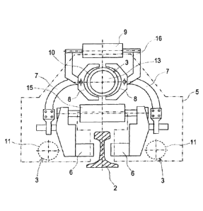
  • At the time the application is open to public inspection;
  • At the time of issue of the patent (grant).
(12) Patent: (11) CA 3015000
(54) English Title: WELDING ASSEMBLY FOR WELDING TWO RAILS OF A TRACK
(54) French Title: GROUPE DE SOUDAGE SERVANT AU SOUDAGE DE DEUX RAILS D'UNE VOIE FERREE
Status: Granted
Bibliographic Data
(51) International Patent Classification (IPC):
  • E01B 29/42 (2006.01)
  • B23K 11/04 (2006.01)
  • B23K 37/00 (2006.01)
  • B23K 37/04 (2006.01)
(72) Inventors :
  • MUHLLEITNER, HEINZ (Austria)
(73) Owners :
  • PLASSER & THEURER EXPORT VON BAHNBAUMASCHINEN GESELLSCHAFT M.B.H. (Austria)
(71) Applicants :
  • PLASSER & THEURER EXPORT VON BAHNBAUMASCHINEN GESELLSCHAFT M.B.H. (Austria)
(74) Agent: RICHES, MCKENZIE & HERBERT LLP
(74) Associate agent:
(45) Issued: 2023-10-17
(86) PCT Filing Date: 2017-03-06
(87) Open to Public Inspection: 2017-10-05
Examination requested: 2022-01-24
Availability of licence: N/A
(25) Language of filing: English

Patent Cooperation Treaty (PCT): Yes
(86) PCT Filing Number: PCT/EP2017/000300
(87) International Publication Number: WO2017/167433
(85) National Entry: 2018-08-17

(30) Application Priority Data:
Application No. Country/Territory Date
GM 68/2016 Austria 2016-04-01

Abstracts

English Abstract

The invention relates to a welding unit (1) for welding two rails (2) of a track, comprising two rail clamping units (5) which are movable relative to each other in a longitudinal direction (4) of the unit. A bus bar (10) which is provided for power transmission is designed as a unit guide (3) which connects both rail clamping units (5) to one another, is spaced apart from displacement drives (11) and extends in a longitudinal direction (4) of the unit. The bus bar (10) is provided with a cooling device and is displaceable in the longitudinal direction (4) of the unit relative to the rail clamping unit (5) which is equipped with the bus bar contacts (8).


French Abstract

L'invention concerne un groupe de soudage (1) servant au soudage de deux rails (2) d'une voie ferrée et présentant deux unités de serrage de rail (5) mobiles l'une par rapport à l'autre dans le sens de la longueur (4) du groupe. Une barre omnibus (10) conçue pour la transmission du courant est réalisée sous la forme d'un dispositif de guidage (3) du groupe reliant l'une à l'autre les deux unités de serrage de rail (5), à distance de mécanismes de déplacement (11) et s'étendant dans le sens de la longueur (4) du groupe. La barre omnibus (10) est équipée d'un dispositif de refroidissement et peut se déplacer dans le sens de la longueur (4) du groupe par rapport à l'unité de serrage de rail (5) équipée des contacts (8) de la barre omnibus.

Claims

Note: Claims are shown in the official language in which they were submitted.

7
We claim:
1. A welding assembly (1) for welding two rails (2) of a track, including
two rail clamping units (5) movable towards one another in an assembly
longitudinal direction (4) by means of displacement drives (11), each rail
clamping unit (5) having a plurality clamping jaws (6) designed to be applied
to a selected said rail (2) in pairs by means of a drive, wherein a plurality
of
said clamping jaws (6) provided for power transmission are connected - with
regard to one of the two rail clamping units (5) - by a power line (7) to a
power
rail contact (8) which is designed to be applied to a power rail (10) by means

of a fixing drive (9) and is displaceable relative thereto,
and wherein:
a) the power rail (10) is configured as an assembly guide (3),
extending in the assembly longitudinal direction (4), which is spaced
from the displacement drives (11) and connects both rail clamping units
(5) to one another,
b) the power rail (10) is equipped with a cooling device (13) and is
displaceable in the assembly longitudinal direction (4) relative to the rail
clamping unit (5) equipped with the power rail contacts (8).
2. A welding assembly according to claim 1, characterized in that the
plurality of clamping jaws (6) provided for power transmission are separate
from a plurality of said clamping jaws (6) provided for rail clamping and, for

contacting the rail (2), are adjustable perpendicularly to the assembly
longitudinal direction (4) by means of a separate clamping drive (15).
CA 3015000 2023-06-16

8
3. A welding
assembly according to one of claims 1 or 2, characterized in
that the two power rail contacts (8) are arranged on a common contact
carriage (16) and designed to be applied to the power rail (10) by means of a
common fixing drive (9).

Description

Note: Descriptions are shown in the official language in which they were submitted.


CA 03015000 2018-08-17
=
=
Welding assembly for welding two rails of a track
[01] The invention relates to a welding assembly for welding two rails of a

track, including two rail clamping units movable towards one another in an
assembly longitudinal direction along assembly guides, each rail clamping
unit having clamping jaws designed to be applied to the rail in pairs by
means of a drive, wherein the clamping jaws provided for power
transmission are connected ¨ with regard to one of the two rail clamping
units ¨ by a power line to a power rail contact which is designed to be
applied to a power rail by means of a fixing drive and is displaceable
relative thereto.
[02] A welding assembly of this type for flash-butt welding is known from
US 8
907 242. Two power rails separated from one another as well as two
power rail contacts are provided for power transmission. The power rail
simultaneously also functions as a hydraulic cylinder for displacement of
the rail clamping units.

2
SUMMARY OF THE INVENTION
[031 It is the object of the present invention to provide a welding assembly
of
the type mentioned at the beginning with which an improved power
transmission is possible.
[041 According to the invention, this object is achieved with a welding
assembly having features described herein.
[05] By using merely a single power rail, a reduction of the structural
expense can be achieved. In addition, the power rail - used, parallel to
the power transmission, only as a guide for the two rail clamping units -
can be optimized with regard to both current conductivity as well as
cooling.
Accordingly, in one aspect, the present invention resides in a welding
assembly for welding two rails of a track, including two rail clamping
units movable towards one another in an assembly longitudinal direction
by means of displacement drives, each rail clamping unit having a
plurality clamping jaws designed to be applied to a selected said rail in
pairs by means of a drive, wherein a plurality of said clamping jaws
provided for power transmission are connected - with regard to one of
the two rail clamping units - by a power line to a power rail contact
which is designed to be applied to a power rail by means of a fixing
drive and is displaceable relative thereto, and wherein: a) the power rail
is configured as an assembly guide, extending in the assembly
longitudinal direction, which is spaced from the displacement drives and
connects both rail clamping units to one another, b) the power rail is
CA 3015000 2023-06-16

2a
equipped with a cooling device and is displaceable in the assembly
longitudinal direction relative to the rail clamping unit equipped with the
power rail contacts.
[06] Further advantages of the invention become apparent from the
drawings and description.
BRIEF DESCRIPTION OF THE DRAWINGS
[07] The invention will be described in more detail below by way of an
example of embodiment shown in the drawing. There is shown in: Fig. 1
a simplified side view of a welding assembly, Fig. 2 a schematic view of
clamping jaws for power transmission, and Fig. 3 an overall view of the
welding
=
CA 3015000 2023-06-16

CA 03015000 2018-08-17
3
assembly, wherein the parts provided for power transmission are shown in
solid lines.
[08] A welding assembly shown in Figs. 1 to 3 is designed for welding two
rails
2 of a track and has rail clamping units 5 movable towards one another in
an assembly longitudinal direction 4 along three assembly guides 3. Each
rail clamping unit 5 is equipped with clamping jaws 6 designed to be
applied to the rail 2 in pairs. As can be seen in particular in Fig. 2, the
two
lower assembly guides 3 positioned at either side of the rails 2 are
configured as hydraulic displacement drives 11 designed for adjusting the
two rail clamping units 5 to one another.
[09] The clamping jaws 6 provided for power transmission are separate from
the clamping jaws 6 provided for clamping the rails (see Fig. 1) and are
connected in each case ¨ with regard to one of the two rail clamping units
5¨ by a power line 7 to a power rail contact 8. These can be applied by
means of a fixing drive 9 to a power rail 10 of tubular cross-section.
[10] In the region between the power rail contacts 8 and a power supply 12,
the
power rail 10 is identical with the assembly guide 3 which extends in the

CA 03015000 2018-08-17
. .
. . ..
4
assembly longitudinal direction 4, is spaced from the two displacement
drives 11 and connects both rail clamping units 5 to one another. In this
section, the assembly guide 3 or power rail 10 has an enlarged cross-
section of copper as well as a cooling device 13 (see Fig. 3).
[11] The power rail 10 or assembly guide 3 is connected only to the rail
clamping unit 5 which has transformers 14 for the power supply 12, and is
thus displaceable in the assembly longitudinal direction 4 relative to the
rail
clamping unit 5 equipped with the power rail contacts 10.
[12] As visible in Fig. 2, the two clamping jaws 6 provided for the power
feed
are adjustable perpendicularly to the assembly longitudinal direction 4 by
way of a separate clamping drive 15 in order to contact the rail 2. The two
power rail contacts 8 of semi-circular design are arranged on a common
contact carriage 16 and can be applied to the power rail 10 by means of
the common fixing drive 9. The contact carriage 16 is mounted for
displacement in the assembly longitudinal direction 4 relative to the
associated rail clamping unit 5.

CA 03015000 2018-08-17
[13] To initiate a welding operation, the rail 2 which is not displaced
relative to
the sleepers (at the right side in Fig. 1) is clamped fast with the aid of the

clamping jaws 6 by the first rail clamping unit 5 equipped with the
transformers 14.
[14] With the aid of the oppositely positioned second rail clamping unit 5,
the
second rail 2 ¨ with pressing-on of the associated clamping jaws 6 not
provided for power transmission, and with actuation of the displacement
drives 11 - is pulled in the direction of the oppositely positioned first rail
2
until a rail gap of about 30 to 35 mm is attained which is required for
initiating the welding operation.
[15] As the next step, the clamping jaws 6 provided for power transmission
are
pressed to the above-mentioned second rail 2, and the two power rail
contacts 8 are pressed to the power rail 10. In further sequence, the said
second rail clamping unit 5 is moved, together with the clamped second
rail 2, further towards the first rail 2. At the same time, a permanent power
supply takes place via the transformers 14, the power rail 10, the power
rail contacts 8, the power line 7 and the connected clamping jaws 6.

CA 03015000 2018-08-17
= 6
[16] Due to the resulting relative displacement between the power
rail 10 and
the clamped-fast power rail contacts 8 with regard to the second rail
clamping unit 5, a slight bending of the two flexible power lines 7 occurs in
the process. After termination of the welding operation, the two power rail
contacts 8 are again spaced from the power rail 10 (see Fig. 2), wherein
the contact carriage 16 is automatically displaced back into its front
starting position by way of spring pre-tensioning.

Representative Drawing
A single figure which represents the drawing illustrating the invention.
Administrative Status

For a clearer understanding of the status of the application/patent presented on this page, the site Disclaimer , as well as the definitions for Patent , Administrative Status , Maintenance Fee  and Payment History  should be consulted.

Administrative Status

Title Date
Forecasted Issue Date 2023-10-17
(86) PCT Filing Date 2017-03-06
(87) PCT Publication Date 2017-10-05
(85) National Entry 2018-08-17
Examination Requested 2022-01-24
(45) Issued 2023-10-17

Abandonment History

There is no abandonment history.

Maintenance Fee

Last Payment of $277.00 was received on 2024-02-15


 Upcoming maintenance fee amounts

Description Date Amount
Next Payment if small entity fee 2025-03-06 $100.00
Next Payment if standard fee 2025-03-06 $277.00

Note : If the full payment has not been received on or before the date indicated, a further fee may be required which may be one of the following

  • the reinstatement fee;
  • the late payment fee; or
  • additional fee to reverse deemed expiry.

Patent fees are adjusted on the 1st of January every year. The amounts above are the current amounts if received by December 31 of the current year.
Please refer to the CIPO Patent Fees web page to see all current fee amounts.

Payment History

Fee Type Anniversary Year Due Date Amount Paid Paid Date
Application Fee $400.00 2018-08-17
Maintenance Fee - Application - New Act 2 2019-03-06 $100.00 2019-02-08
Maintenance Fee - Application - New Act 3 2020-03-06 $100.00 2020-02-13
Maintenance Fee - Application - New Act 4 2021-03-08 $100.00 2021-02-10
Request for Examination 2022-03-07 $814.37 2022-01-24
Maintenance Fee - Application - New Act 5 2022-03-07 $203.59 2022-02-18
Maintenance Fee - Application - New Act 6 2023-03-06 $210.51 2023-02-09
Final Fee $306.00 2023-08-30
Maintenance Fee - Patent - New Act 7 2024-03-06 $277.00 2024-02-15
Owners on Record

Note: Records showing the ownership history in alphabetical order.

Current Owners on Record
PLASSER & THEURER EXPORT VON BAHNBAUMASCHINEN GESELLSCHAFT M.B.H.
Past Owners on Record
None
Past Owners that do not appear in the "Owners on Record" listing will appear in other documentation within the application.
Documents

To view selected files, please enter reCAPTCHA code :


To view images, click a link in the Document Description column. To download the documents, select one or more checkboxes in the first column and then click the "Download Selected in PDF format (Zip Archive)" or the "Download Selected as Single PDF" button.

List of published and non-published patent-specific documents on the CPD .

If you have any difficulty accessing content, you can call the Client Service Centre at 1-866-997-1936 or send them an e-mail at CIPO Client Service Centre.


Document
Description 
Date
(yyyy-mm-dd) 
Number of pages   Size of Image (KB) 
Maintenance Fee Payment 2020-02-13 1 52
Maintenance Fee Payment 2021-02-10 1 55
Request for Examination 2022-01-24 1 58
Maintenance Fee Payment 2022-02-18 1 55
Maintenance Fee Payment 2023-02-09 2 115
Examiner Requisition 2023-03-02 3 167
Abstract 2018-08-17 1 16
Claims 2018-08-17 2 42
Drawings 2018-08-17 2 78
Description 2018-08-17 6 147
Representative Drawing 2018-08-17 1 8
International Search Report 2018-08-17 2 59
Amendment - Abstract 2018-08-17 2 80
National Entry Request 2018-08-17 4 117
Cover Page 2018-08-27 1 48
Maintenance Fee Payment 2019-02-08 1 54
Amendment 2023-06-16 11 287
Amendment 2023-06-13 10 215
Description 2023-06-13 7 231
Claims 2023-06-13 2 58
Description 2023-06-16 7 225
Claims 2023-06-16 2 56
Final Fee / Completion Fee - PCT 2023-08-30 1 75
Representative Drawing 2023-10-06 1 13
Cover Page 2023-10-06 1 49
Electronic Grant Certificate 2023-10-17 1 2,527