Note: Descriptions are shown in the official language in which they were submitted.
323048-2
VERTICAL TAKEOFF AND LANDING AIRCRAFT
FIELD
[0001] The
present subject matter relates generally to a propulsion system for an
aircraft having vertical takeoff and landing capabilities.
BACKGROUND
[0002] Aircraft
have been developed with a capability for performing vertical takeoff
and landings. Such a capability may allow for the aircraft to reach relatively
rugged
terrains and remote locations, where it may be impractical or infeasible to
construct a
runway large enough to allow for a traditional aircraft (lacking vertical
takeoff capability)
to takeoff or land.
[0003] Typically
these aircraft capable of performing vertical takeoff and landings
have engines and propulsors that are vectored to generate both vertical thrust
and forward
thrust. However, the design characteristics that make a propulsor efficient
for vertical
takeoff and landing may not result in efficient forward flight. Accordingly,
existing
aircraft capable of performing vertical takeoff and landing include propulsors
that may be
well suited for generating vertical thrust, but that may not be very well
suited for efficient
forward flight. This discrepancy between vertical takeoff and landing and
cruise
efficiency is exaggerated as cruise speed increases. An
aircraft capable of more
efficiently performing a vertical takeoff and landing combined with high speed
cruise
would therefore be useful.
BRIEF DESCRIPTION
[0004] Aspects
and advantages of the invention will be set forth in part in the
following description, or may be obvious from the description, or may be
learned through
practice of the invention.
1
CA 3015096 2018-08-23
323048-2
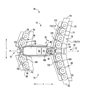
[0005] In one embodiment of the present disclosure an aircraft is provided
defining a
vertical direction and a transverse direction. The aircraft includes a
fuselage; a wing
coupled to, and extending from, the fuselage; and a propulsion system. The
propulsion
system includes a plurality of electric fans integrated into the wing and
oriented to
generate thrust along the vertical direction, the plurality of electric fans
arranged along a
length of the wing and including an outer-most electric fan along the
transverse direction
relative to the fuselage, the outer-most electric fan being at least one of a
variable pitch
fan or a variable speed fan to provide increased stability to the aircraft.
[0006] In certain exemplary embodiments the plurality of electric fans
further include
at least one interior electric fan positioned closer to the fuselage along the
transverse
direction than the outermost electric fan, wherein the at least one interior
electric fan is
configured differently than the outermost electric fan.
[0007] For example, in certain exemplary embodiments the outermost
electric fan is a
variable pitch fan, and wherein the at least one interior electric fan is a
fixed-pitch fan.
[0008] In certain exemplary embodiments the plurality of electric fans
further include
at least one interior electric fan positioned closer to the fuselage along the
transverse
direction than the outermost electric fan, wherein the at least one interior
electric fan is
configured in the same manner as the outermost electric fan.
[0009] In certain exemplary embodiments the wing is a first wing, wherein
the
plurality of electric fans of the hybrid electric propulsion system is a first
plurality of
electric fans. In such an exemplary embodiment, the aircraft may further
include a second
wing, a third wing, and a fourth wing, wherein the hybrid electric propulsion
system
further includes a second plurality of electric fans integrated into the
second wing and
arranged along a length of the second wing, a third plurality of electric fans
integrated
into the third wing and arranged along a length of the third wing, and a
fourth plurality of
electric fans integrated into the fourth wing and arranged along a length of
the fourth
wing, wherein each of the second plurality of electric fans, the third
plurality of electric
2
CA 3015096 2018-08-23
323048-2
fans, and fourth plurality of electric fans are oriented to generate thrust
along the vertical
direction.
[0010] For example, in certain exemplary embodiments the second plurality
of
electric fans includes an outermost electric fan along the transverse
direction relative to
the fuselage being at least one of a variable pitch fan or a variable speed
fan, wherein the
third plurality of electric fans includes an outermost electric fan along the
transverse
direction relative to the fuselage being at least one of a variable pitch fan
or a variable
speed fan, and wherein the fourth plurality of electric fans includes an
outermost electric
fan along the transverse direction relative to the fuselage being at least one
of a variable
pitch fan or a variable speed fan.
[0011] In certain exemplary embodiments the wing is a fixed wing including
a
variable geometry portion movable between a vertical thrust position in which
the
plurality of electric fans are exposed and a forward thrust position in which
the plurality
of electric fans are each substantially completely covered.
[0012] For example, in certain exemplary embodiments the variable geometry
portion
of the wing forms an exhaust arrangement for the plurality of electric fans
when moved to
the vertical thrust position.
[0013] For example, in certain exemplary embodiments the outermost
electric fan
defines a fan diameter, wherein the exhaust arrangement formed by the wing
defines a
length along the vertical direction, and wherein the length is greater than or
equal to the
fan diameter.
[0014] For example, in certain exemplary embodiments each of the plurality
of
electric fans define substantially the same fan diameter.
[0015] In certain exemplary embodiments the hybrid electric propulsion
system
further includes a power source including a combustion engine and an electric
machine,
3
CA 3015096 2018-08-23
323048-2
the electric machine powered by the combustion engine, and wherein the
plurality of
electric fans are driven at least in part by the electric machine.
[0016] For example, in certain exemplary embodiments the hybrid electric
propulsion
system further includes a forward thrust propulsor, wherein the forward thrust
propulsor
is selectively or permanently mechanically coupled to the combustion engine.
[0017] For example, in certain exemplary embodiments the combustion engine
is a
turboshaft engine.
[0018] In certain exemplary embodiments the wing defines an aspect ratio
greater
than about 3:1.
[0019] For example, in certain exemplary embodiments the wing is an aft
wing. In
such an exemplary embodiment, the aircraft may further include a forward wing,
the
forward wing attached to, and extending from, the fuselage at a location
forward of the
aft wing, wherein the forward wing defines an aspect ratio greater than or
equal to about
1.5:1.
[0020] In certain exemplary embodiments the hybrid electric propulsion
system
further includes an electric power source and an electric power bus, wherein
the electric
power bus electrically connects the electric power source to each of the
plurality of
electric fans.
[0021] For example, in certain exemplary embodiments the electric power
bus
includes a plurality of electric power controllers with each of the plurality
of electric
power controllers associated with one of the plurality of electric fans,
wherein each
electric power controller is configured to modify electrical power provided
from the
electric power source to the respective electric fan.
[0022] For example, in certain exemplary embodiments each of the plurality
of
electric fans are configured as variable speed fans.
4
CA 3015096 2018-08-23
323048-2
[0023] In certain exemplary embodiments each of the plurality of electric
fans are
fixed in orientation within the wing.
[0024] In certain exemplary embodiments the electric power source is
configured to
generate at least about one megawatt of electrical power during operation.
[0025] These and other features, aspects and advantages of the present
invention will
become better understood with reference to the following description. The
accompanying
drawings illustrate embodiments of the invention and, together with the
description, serve
to explain the principles of the invention.
BRIEF DESCRIPTION OF THE DRAWINGS
[0026] A full and enabling disclosure of the present invention, including
the best
mode thereof, directed to one of ordinary skill in the art, is set forth in
the specification,
which makes reference to the appended figures, in which:
[0027] Fig. 1 is a perspective view of an aircraft according to various
exemplary
embodiments of the present disclosure.
[0028] Fig. 2 is a top, schematic of the exemplary aircraft of Fig. 1 in a
vertical flight
position.
[0029] Fig. 3 is atop, schematic of the exemplary aircraft of Fig. 1 in a
forward flight
position.
[0030] Fig. 4 is a schematic view of a power source of the exemplary
aircraft of Fig.
1.
[0031] Fig. 5 is a side, schematic view of an outermost vertical thrust
electric fan in
accordance with an exemplary embodiment of the present disclosure in a first
position.
Date Recue/Date Received 2020-12-15
323048-2
[0032] Fig. 6 is a side, schematic view of the exemplary outermost
vertical thrust
electric fan of Fig. 5 in a second position.
[0033] Fig. 7 is a side, schematic view of a wing of the exemplary
aircraft of Fig. 1 in
accordance with an exemplary embodiment of the present disclosure in a forward
flight
position.
[0034] Fig. 8 is a side, schematic view of the exemplary wing of Fig. 7 in
a vertical
flight position.
[0035] Fig. 9 is a top, schematic view of an aircraft according to another
exemplary
embodiment of the present disclosure.
DETAILED DESCRIPTION
[0036] Reference will now be made in detail to present embodiments of the
invention, one or more examples of which are illustrated in the accompanying
drawings.
The detailed description uses numerical and letter designations to refer to
features in the
drawings. Like or similar designations in the drawings and description have
been used to
refer to like or similar parts of the invention.
[0037] As used herein, the terms "first", "second", and "third" may be
used
interchangeably to distinguish one component from another and are not intended
to
signify location or importance of the individual components.
[0038] The terms "forward" and "aft" refer to relative positions within a
gas turbine
engine or vehicle, and refer to the normal operational attitude of the gas
turbine engine or
vehicle. For example, with regard to a gas turbine engine, forward refers to a
position
closer to an engine inlet and aft refers to a position closer to an engine
nozzle or exhaust.
[0039] The terms "upstream" and "downstream" refer to the relative
direction with
respect to fluid flow in a fluid pathway. For example, "upstream" refers to
the direction
6
CA 3015096 2018-08-23
323048-2
from which the fluid flows, and "downstream" refers to the direction to which
the fluid
flows.
[0040] The terms "coupled," "fixed," "attached to," and the like refer to
both direct
coupling, fixing, or attaching, as well as indirect coupling, fixing, or
attaching through
one or more intermediate components or features, unless otherwise specified
herein.
[0041] The singular forms "a", "an", and "the" include plural references
unless the
context clearly dictates otherwise.
[0042] Approximating language, as used herein throughout the specification
and
claims, is applied to modify any quantitative representation that could
permissibly vary
without resulting in a change in the basic function to which it is related.
Accordingly, a
value modified by a term or terms, such as "about", "approximately", and
"substantially",
are not to be limited to the precise value specified. In at least some
instances, the
approximating language may correspond to the precision of an instrument for
measuring
the value, or the precision of the methods or machines for constructing or
manufacturing
the components and/or systems. For example, the approximating language may
refer to
being within a 10 percent margin.
[0043] Here and throughout the specification and claims, range limitations
are
combined and interchanged, such ranges are identified and include all the sub-
ranges
contained therein unless context or language indicates otherwise. For example,
all ranges
disclosed herein are inclusive of the endpoints, and the endpoints are
independently
combinable with each other.
[0044] The present disclosure is generally related to an aircraft capable
of performing
vertical takeoff and landing maneuvers. More specifically, the present
disclosure is
related to such an aircraft including a fuselage, a plurality of wings coupled
to and
extending from the fuselage, and a propulsion system. The propulsion system
includes a
plurality of electric fans integrated into each of the wings. Each of such
plurality of
electric fans are oriented to generate thrust along a vertical direction of
the aircraft and
7
CA 3015096 2018-08-23
323048-2
are arranged along a length of the respective wing. Along each wing, the
plurality of
electric fans included includes an outermost electric fan (i.e., outermost
relative to the
fuselage). The outermost electric fan of each of these wings is at least one
of a variable
pitch fan or a variable speed fan in order to provide increased ability for
the aircraft.
[0045] Referring now to the drawings, wherein identical numerals indicate
the same
elements throughout the Figures ("Figs."), Figs. 1 through 3 depict an
aircraft 10 in
accordance with various embodiments of the present disclosure. More
specifically, Fig. 1
provides a perspective view of the exemplary aircraft 10; Fig. 2 provides a
top, schematic
view of the exemplary aircraft 10 of Fig. 1 in a vertical thrust
configuration; and Fig. 3
provides a top, schematic view of the exemplary aircraft 10 of Fig. 1 in a
forward thrust
configuration. As shown in Figs. 1 through 3 collectively, the aircraft 10
defines a
longitudinal direction L (and a longitudinal centerline 12 that extends
therethrough), a
vertical direction V, and a transverse direction T. Additionally, the aircraft
10 defines a
port side 14 and an opposite starboard side 16.
[0046] The aircraft 10 includes a fuselage 18 extending between a forward
end 20
and an aft end 22 generally along the longitudinal centerline 12 of the
aircraft 10. The
aircraft 10 additionally includes four wings, each attached to or formed
integrally with
the fuselage 18. Specifically, for the embodiment depicted, the aircraft 10
includes a first
wing, a second wing, a third wing, and a fourth wing, or more particularly an
aft
starboard wing 24, an aft port wing 26, a forward starboard wing 28, and a
forward port
wing 30, and. Each of these wings 24, 26, 28, 30 is attached to, or formed
integrally with,
the fuselage 18 and extends from the fuselage 18 outwardly generally along the
transverse direction T (i.e., outwardly relative to the fuselage 18). It will
be appreciated
that although the forward port wing 30 and forward starboard wing 28 are
depicted as
being separate wings, in other embodiments, the forward port wing 30 and
forward
starboard wing 28 may be formed integrally, and together attached to the
fuselage 18.
Similarly, although the aft port wing 26 and aft starboard wing 24 are
depicted as being
8
CA 3015096 2018-08-23
323048-2
separate wings, in other embodiments, the aft port wing 26 and aft starboard
wing 24 may
be formed integrally, and together attached the fuselage 18.
[0047] Although not depicted, in other embodiments, the aircraft 10 may
additionally
include one or more stabilizers, such as one or more vertical stabilizers,
horizontal
stabilizers, etc. Moreover, it will be appreciated, that although not
depicted, in certain
embodiments, one or more of the wings may additionally include flaps, such as
leading-
edge flaps or trailing edge flaps, for assisting with controlling the aircraft
10 during
flight.
[0048] Referring still to Figs. 1 through 3, the exemplary aircraft 10
further includes a
propulsion system 32 for providing the aircraft 10 with a desired amount of
thrust during
operation. Broadly speaking, the exemplary propulsion system 32 includes a
plurality of
vertical thrust electric fans (or "VTE fans") for generating vertical thrust
during
operation, a forward thrust propulsor 34, and a power source 36 for driving
the plurality
of VTE fans and the forward thrust propulsor 34. Additionally, for the
embodiment
depicted, the propulsion system 32 includes an electric communication bus 38
for, e.g.,
providing electrical power from the power source 36 to the plurality of VTE
fans.
[0049] More specifically, for the embodiment depicted, the power source 36
includes
a combustion engine 40, an electric machine 42, and an electric energy storage
unit 44.
The combustion engine 40 is coupled to the electric machine 42. Accordingly,
in at least
certain embodiments, the combustion engine 40 may drive the electric machine
42 such
that the electric machine 42 generates electrical power. In such a manner, the
electric
machine 42 may be configured as an electric generator and the propulsion
system 32 may
be referred to as a hybrid electric propulsion system. Further, with such an
exemplary
embodiment the electric machine 42 may provide the electrical power to, e.g.,
the
plurality of VTE fans, to the electric energy storage unit 44, or both. In
such a manner,
the plurality of VTE fans may be driven by the power source 36, and more
particularly,
may be driven at least in part by the electric machine 42.
9
CA 3015096 2018-08-23
323048-2
[0050] Referring now briefly to Fig. 4, a schematic view is provided of
the exemplary
combustion engine 40 of the power source 36 of the propulsion system 32
described
above with reference to Figs. 1 through 3. For the embodiment depicted, the
combustion
engine 40 is a turboshaft engine. The turboshaft engine includes in serial
flow order, a
compressor section including a low pressure compressor 46 and a high pressure
compressor 48, a combustion section 50, and a turbine section including a high
pressure
turbine 52 and a low pressure turbine 54. During operation, a flow of air is
received
within the compressor section and is progressively compressed as it flows
therethrough,
i.e., as it flows from the low pressure compressor 46 to the high pressure
compressor 48.
The compressed air is then provided to the combustion section 50 where it is
mixed with
fuel and burned to generate hot combustion gas. The aircraft 10 further
includes a fuel
tank 56 for providing the fuel to the combustion section 50 (see Figs. 2 and
3).
[0051] The hot combustion gas is expanded through the turbine section
where
rotational energy is extracted therefrom. Specifically, the hot combustion gas
rotates the
high pressure turbine 52 and the low pressure turbine 54 as the gas flows
therethrough
and is expanded. As is depicted in phantom, these components may be enclosed
within a
casing 58 within, e.g., the fuselage 18 of the aircraft 10. Although not
depicted, the hot
combustion gas may be exhausted, e.g., to atmosphere, from the low pressure
turbine 54.
[0052] Also for the embodiment depicted, the high pressure turbine 52 is
connected
to the high pressure compressor 48 through a high pressure shaft or spool 60,
such that a
rotation of the high pressure turbine 52 additionally rotates the high
pressure compressor
48. Similarly, the low pressure turbine 54 is connected to the low pressure
compressor 46
through a low pressure shaft or spool 62, such that rotation of the low
pressure turbine 54
additionally rotates the low pressure compressor 46. It should be appreciated,
however,
that in other exemplary embodiments, the turbomachine may have any other
suitable
configuration. For example, in other exemplary embodiments, the turbomachine
may
have any other suitable number of compressors, turbines, and/or shafts/spools.
Further,
although for the embodiment depicted, the combustion engine 40 is configured
as a
CA 3015096 2018-08-23
323048-2
turboshaft engine, in other embodiments, the combustion engine 40 may have any
other
suitable configuration, such as any suitable reciprocating or internal
combustion engine.
[0053] Moreover, for the embodiment depicted, the low pressure shaft 62
additionally
drives an output shaft oh the turboshaft engine, and more specifically drives
a first output
shaft, or a forward output shaft 64, and also drives a second output shaft, or
an aft output
shaft 65. The forward output shaft 64 extends to the electric machine 42, and
the aft
output shaft 65 extends to the forward thrust propulsor 34. Accordingly, a
rotation of the
turboshaft engine provides, at least during certain operations, rotational
energy to the
electric machine 42, and the electric machine 42 is configured to convert the
rotational
energy to generate electrical power. More specifically, it will be appreciated
that in at
least certain embodiments, the electric machine 42 generally includes a rotor
66 and a
stator 68. The rotational energy of the turboshaft engine is provided via the
forward
output shaft 64 and configured to rotate the rotor 66 of the electric machine
42 relative to
the stator 68. Such relative movement may generate electrical power.
[0054] It will be appreciated that in certain exemplary embodiments, the
electric
machine 42, when operate as an electric generator, may be a relatively
powerful electric
generator. For example, in certain embodiments, the exemplary electric machine
42 may
be configured to generate at least about one megawatt of electrical power
during
operation. For example, in certain embodiments, the electric machine 42 may be
configured to generate at least about 1.5 megawatts, such as at least about
two megawatts,
such as up to about ten megawatts of electrical power during operation.
However, in
other embodiments, any other suitable sized electric machine may be provided.
[0055] Inclusion of a turboshaft engine and electric machine 42 in
accordance with
such an exemplary embodiment may allow for the power source 36 to generate a
relatively high amount of electric power and to provide such electric power to
the
plurality of VTE fans of the propulsion system 32 during at least certain
operations.
11
CA 3015096 2018-08-23
323048-2
[0056] Referring back to Figs. 2 and 3, as stated the power source 36 of
the
propulsion system 32 further includes the electric energy storage unit 44. The
electric
energy storage unit 44 may be a battery or other suitable component for
storing electrical
power. The electric energy storage unit 44 may receive electrical power from,
e.g., the
generator, and store electrical power for use during operation of the aircraft
10. For
example, the electric energy storage unit 44 may receive and store electrical
power from
the electric machine 42 (operating as an electric generator) during certain
operations, and
subsequently provide electrical power to the plurality of VTE fans during
other
operations. Additionally, in still other operations, the electric energy
storage unit 44 may
provide electrical power back to the electric machine 42 to, e.g., power the
aft fan for
short durations, power the combustion engine 40 during emergency operations,
or add
power to the forward thrust propulsor 34 and/or to the combustion engine 40
during high
power demand operations. Accordingly, with such exemplary embodiment, the
electric
machine 42 may further be configured as an electric motor.
[0057] Referring to a first of the plurality of wings of the aircraft 10,
and more
particularly to the aft starboard wing 24 depicted in Fig. 2, the propulsion
system 32
includes a first plurality of VTE fans 70 integrated into the aft starboard
wing 24 and
oriented to generate thrust along the vertical direction V. In such a manner,
each of the
first plurality of VTE fans 70 are vertical lift fans, and as will be
discussed in more detail
below, are fixed in position such that they are only capable of generating
thrust
substantially along the vertical direction V of the aircraft 10. As will be
discussed in
greater detail below, each of the first plurality of VTE fans 70 is
electrically coupled to
the power source 36 to receive electrical power from, e.g., the electric
machine 42 or the
electric energy storage unit 44.
[0058] It will be appreciated, that as used herein, the term "along the
vertical
direction V of the aircraft 10" refers to a vertical direction defined by a
normal
orientation of the aircraft 10. For example, if the aircraft 10 is, e.g.,
tilted forward during
certain operations, the first plurality of VTE fans 70 may provide thrust in a
direction that
12
CA 3015096 2018-08-23
323048-2
is still along the vertical direction of the aircraft 10, but tilted relative
to absolute vertical
direction. Additionally, in this context, the term "substantially" refers to
being within
about thirty degrees of the vertical direction V of the aircraft 10.
[0059] Additionally, the first plurality of VTE fans 70 are arranged along
a length of
the aft starboard wing 24 generally along the transverse direction T.
Additionally, the first
plurality of VTE fans 70 includes an outermost VTE fan 72 along the transverse
direction
T relative to the fuselage 18 of the aircraft 10 and at least one interior VTE
fan 74. More
particularly, for the embodiment of Fig. 2, the first plurality of VTE fans 70
includes
three interior VTE fans 74. However, in other embodiments, the first plurality
of VTE
fans 70 may have any other suitable number of interior fans 74, as will be
discussed in
more detail below. It will be appreciated that the outermost VTE fan 72 is at
least one of
a variable pitch fan or a variable speed fan to provide increased stability to
the aircraft 10.
[0060] More specifically, referring now also to Figs. 5 and 6, it will be
appreciated
that for the embodiment depicted, the outermost VTE fan 72 of the first
plurality of VTE
fans 70 is a variable pitch fan. More particularly, Figs. 5 and 6 each provide
a side, cross-
sectional view of the outermost VTE fan 72 of the first plurality of VTE fans
70. As is
depicted, the outermost VTE fan 72 generally includes a fan 76 having a
plurality of fan
blades 78 coupled to a disk 80 and an electric motor 82. The electric motor 82
is
electrically coupled to the electric communication bus 38, such that the
electric
communication bus 38 may provide electrical power to the electric motor 82
during at
least certain operations of the aircraft 10. Each of the plurality of fan
blades 78 of the fan
76 may be rotatably coupled to the disk 80 about a respective pitch axis 84.
The plurality
of fan blades 78 are rotatable by a pitch change mechanism 86, which may
change a pitch
of each of the plurality of fan blades 78 of the outermost VTE fan 72 of the
first plurality
of VTE fans 70, e.g., in unison.
[0061] As will be appreciated, by changing the pitch of the plurality of
fan blades 78
of the outermost VTE fan 72, an amount of vertical thrust generated by the
outermost
VTE fan 72 may be modified without requiring a change to the rotational speed.
For
13
CA 3015096 2018-08-23
323048-2
example, Fig. 5 depicts the outermost VTE fan 72 with each of the plurality of
fan blades
78 defining a relatively high pitch, such that a relatively high amount of
thrust is
generated by the outermost VTE fan 72 during operation of the outermost VTE
fan 72.
By contrast, Fig. 6 depicts the outermost VTE fan 72 with each of the
plurality of fan
blades 78 defining a relatively low pitch, such that a relatively low amount
of thrust is
generated by the outermost VTE fan 72 during operation of the outermost VTE
fan 72.
[0062] Referring back to Fig. 2, it will be appreciated that the
propulsion system 32
includes a similar plurality of electric fans integrated into the other wings
26, 28, 30 of
the aircraft 10. Each of these electric fans are also oriented to generate
thrust substantially
along the vertical direction V of the aircraft 10, and in such a manner may
therefore also
be configured as VTE fans. More specifically, the propulsion system 32 further
includes a
second plurality of VTE fans 88 integrated into the aft port wing 26 and
arranged along a
length of the aft port wing 26, a third plurality of VTE fans 90 integrated
into the forward
starboard wing 28 and arranged along a length of the forward starboard wing
28, and a
fourth plurality of VTE fans 92 integrated into the forward port wing 30 and
arranged
along a length of the forward port wing 30.
[0063] As with the first plurality of VTE fans 70, the second plurality of
VTE fans 88
includes an outermost VTE fan 94 along the transverse direction T.
Additionally, the
third plurality of VTE fans 90 also includes an outermost VTE fan 96 along the
transverse direction T and the fourth plurality of VTE fans 92 includes an
outermost VTE
fan 98 along the transverse direction T. The outermost VTE fans 94, 96, 98 of
the second
plurality of VTE fans 88, of the third plurality of VTE fans 90, and of the
fourth plurality
of VTE fans 92, respectively, are each also configured as one of a variable
pitch fan or a
variable speed fan. More particularly, for the embodiment of Fig. 2, each of
such
outermost VTE fans 94, 96, 98 are configured as variable pitch fans.
Accordingly, each
of such outermost VTE fans 94, 96, 98 may be configured in substantially the
same
manner as the outermost VTE fan 72 of the first plurality of VTE fans 70 (see,
e.g., Figs.
and 6).
14
CA 3015096 2018-08-23
323048-2
[0064] Moreover,
as is depicted in Fig. 2, the electric communication bus 38
electrically connects the power source 36, e.g., the electric machine 42
and/or the electric
energy storage unit 44, to each of the pluralities of VTE fans 70, 88, 90, 92.
Notably, for
the embodiment depicted, the electric communication bus 38 includes a main
controller
100 and a plurality of electric power controllers 102. The main controller 100
is
electrically connected to both the electric machine 42 and the electric energy
storage unit
44 and is configured to, e.g., direct electrical power from one or both of the
electric
machine 42 and electric energy storage unit 44 to each of the VTE fans. For
example, in
certain operations, the main controller 100 may direct electrical power solely
from the
electric machine 42 to each of the pluralities of VTE fans 70, 88, 90, 92, may
direct
electrical power solely from the electric energy storage unit 44 to each of
the pluralities
of VTE fans 70, 88, 90, 92, may direct electrical power solely from the
electric machine
42 to the electric energy storage unit 44 (e.g., during forward flight), or
may direct
electrical power from the electric energy storage unit 44 to the electric
machine 42 (e.g.,
during emergency operations or high-power operations) and/or to one or more of
the
pluralities of VTE fans 70, 88, 90, 92. Other operations are contemplated as
well.
[0065] Moreover, for the exemplary embodiment of Fig. 2 the electric
communication bus 38 includes an electric power controller 102 for each VTE
fan (i.e.,
each VTE fan of the first plurality of VTE fans 70, of the second plurality of
VTE fans
88, of the third plurality of VTE fans 90, and of the fourth plurality of VTE
fans 92).
Additionally, each of the plurality of electric power controllers 102 is
associated with one
VTE fan of the pluralities of VTE fans 70, 88, 90, 92. More specifically,
still, the power
source 36 is electrically coupled to each VTE fan of the pluralities of VTE
fans 70, 88,
90, 92 through such electric power controller 102 associated with the
individual VTE fan.
In such a manner, the electric power controller 102 may modify the electric
power
provided from the power source 36 to the respective VTE fan. Accordingly, for
the
embodiment shown, the propulsion system 32 includes twelve electric power
controllers
102, one for each of the twelve VTE fans included within the propulsion system
32.
CA 3015096 2018-08-23
323048-2
[0066] In certain exemplary embodiments, each of the electric power
controllers 102
may be one or more of a power converter, a power inverter, or a power
transformer.
Accordingly, in certain exemplary embodiments, the electric power controllers
102 may
be configured to convert electrical power received through the electric
communication
bus 38 from alternating current ("AC") electrical power to direct current
("DC")
electrical power, or vice versa, and further may be configured in at least
certain
embodiments to modify an amount of the electrical power (e.g., a voltage or a
current)
received through the electric communication bus 38 from the power source 36
before
transferring such electrical power to a respective VTE fan.
[0067] Accordingly, in at least certain embodiments each of the electric
power
controllers 102 may modify an amount of electrical power provided to a
respective VTE
fan, which as will be appreciated, may allow for the aircraft 10, and more
specifically
may allow for the main controller 100, to modify a rotational speed of each
VTE fan of
the pluralities of VTE fans 70, 88, 90, 92. For example, each of the electric
power
controllers 102 may be operably coupled to the main controller 100 through,
e.g., a wired
or wireless communication bus (not shown), such that the main controller 100
may
control the electrical power provided to each of the individual VTE fans. The
main
controller 100 may be integrated into, or otherwise operably connected to, the
control
system of the aircraft 10.
[0068] Accordingly, it will be appreciated that in at least certain
embodiments each
VTE fan of the pluralities of VTE fans 70, 88, 90, 92 may be a variable speed
fan.
Accordingly, by modifying an amount of electrical power provided to each VTE
fan
through a respective electric power controller 102, the aircraft 10 may modify
a rotational
speed of each of the respective VTE fans, and therefore an amount of vertical
thrust
provided by each of the respective VTE fan. In such a manner, the aircraft 10
may allow
for more dynamic control during vertical takeoff and landing, or other
vertical thrust
operations.
16
CA 3015096 2018-08-23
323048-2
[0069] It should be appreciated, however, that in other exemplary
embodiments, the
aircraft 10, or rather, the electric communication bus 38 may not include an
electric
power controller 102 for each of the individual VTE fans. Instead, for
example, in other
embodiments, the electric communication bus 38 may include a single electric
power
controller 102 for each of the individual pluralities of VTE fans 70, 88, 90,
92. In still
other embodiments, however, any other suitable configuration may be provided.
[0070] With reference back to the first plurality of VTE fans 70, and as
will be
discussed with reference to Figs. 7 and 8, below, providing a cross-sectional
view of an
interior VTE fan 74 of the first plurality of VTE fans 70, for the embodiment
of Fig. 2, at
least one of the interior VTE fans 74 is configured differently than the
outermost VTE fan
72. More specifically, for the embodiment depicted, the interior VTE fans 74
of the first
plurality of VTE fans 70 are each configured as fixed pitch fans, while the
outermost
VTE fan 72 is configured as a variable pitch fan (discussed above). Such a
configuration
may allow at least some of the first plurality of VTE fans 70 to have a more
simple
configuration, while the first plurality of VTE fans 70 may still provide a
desired amount
of stability for the aircraft 10 due to the inclusion of a variable pitch
outermost VTE fan
72.
[0071] Similarly, the second plurality of VTE fans 88 includes at least
one interior
VTE fan 104, the third plurality of VTE fans 90 includes these one interior
VTE fan 106,
and the fourth plurality of VTE fans 92 includes at least one interior VTE fan
108. More
specifically, the second plurality of VTE fans 88 includes three interior VTE
fans 104,
the third plurality of VTE fans 90 includes one interior VTE fan 106, and the
fourth
plurality of VTE fans 92 includes one interior VTE fan 108. For the embodiment
depicted, each of the at least one interior VTE fans 104, 106, 108 of the
respective
pluralities of VTE fans 88, 90, 92 is configured differently than the
outermost VTE fan
94, 96, 98 of the respective pluralities of VTE fans 88, 90, 92.
[0072] It will be appreciated, however, that in other exemplary
embodiments, each of
the respective pluralities of VTE fans 70, 88, 90, 92 may have any other
suitable number
17
CA 3015096 2018-08-23
323048-2
of interior VTE fans 74, 104, 106, 108, and further that the at least one
interior VTE fan
74, 104, 106, 108 of each of the pluralities of VTE fans 70, 88, 90, 92 may be
configured
in the same manner as the outermost VTE fan 72, 94, 96, 98 of the respective
plurality of
VTE fans 70, 88, 90, 92. For example, in other exemplary embodiments, each of
the first
plurality of VTE fans 70, second plurality of VTE fans 88, third plurality of
VTE fans 90,
and fourth plurality of VTE fans 92 may be configured as variable speed, fixed
pitch fans,
or alternatively, may each be configured as variable speed, variable pitch
fans.
[0073] Moreover, as briefly stated above, and as is shown in Figs. 2 and
3, each of
the wings 24, 26, 28, 30 are fixed wings including a variable control portion
that is
generally movable between a vertical thrust position (Fig. 2) and a forward
thrust position
(Fig. 3). More specifically, referring now also to Fig. 7 and 8, providing a
side, cross-
sectional view of the aft starboard wing 24 and an interior VTE fan 74 of the
first
plurality of VTE fans 70, the aft starboard wing 24 (as well as the other
wings 24, 26, 28,
30, discussed in more detail below) generally includes a variable geometry
portion 110.
The variable geometry portion 110 is movable between a forward thrust position
(Fig. 7),
one or more transitional positions (not shown), and a vertical thrust position
(Fig. 8), and
further is generally formed of a surface portion of the respective wings 24,
26, 28, 30. As
will be appreciated, however, a main body or frame portion of the wings 24,
26, 28, 30
remain stationary during this movement.
[0074] When the variable geometry portion 110 is moved from the forward
thrust
position to the vertical thrust position, the first plurality of VTE fans 70
are exposed. By
contrast, when the variable geometry portion 110 is moved from the vertical
thrust
position to the forward thrust position, the first plurality of VTE fans 70
are substantially
completely covered. For the embodiment depicted, the variable geometry portion
110
forms an exhaust arrangement for the first plurality of VTE fans 70 when moved
to the
vertical thrust position. As used herein, the term "exhaust arrangement" refer
generally to
any structure located downstream of the respective fan configured to channel
at least a
portion of an airflow from the respective fan to increase a power loading
(i.e., a ratio of
18
CA 3015096 2018-08-23
323048-2
thrust produced to an amount of power received) of such fan. For example, the
exhaust
arrangement may be configured generally as a nozzle or diffuser for the
respective fans.
[0075] More specifically, for the embodiment depicted, the aft starboard
wing 24, or
rather, the variable geometry portion 110 of the aft starboard wing 24,
generally includes
a forward section 112 and an aft section 114. Referring back briefly to Figs.
2 and 3, it
will be appreciated that for the embodiment shown, the forward section 112 and
the aft
section 114 of the variable geometry portion 110 each extends from the
innermost VTE
fan of the first plurality of VTE fans 70 to the outermost VTE fan 72 of the
first plurality
of VTE fans 70. In such a manner, when the variable geometry portion 110 is
moved to
the vertical thrust position, the exhaust arrangement formed by the variable
geometry
portion 110 also extends from the innermost VTE fan of the first plurality of
VTE fans 70
to the outermost VTE fan 72 of the first plurality of VTE fans 70.
[0076] Referring particularly to Fig. 7, when the variable geometry
portion 110 of the
aft starboard wing 24 is in the forward thrust position, the forward section
112 and the aft
section 114 together define at least in part an airfoil cross-sectional shape.
Such may
allow for relatively efficient forward flight for the aircraft 10. By
contrast, however, as is
depicted in Fig. 8, when the variable geometry portion 110 of the aft
starboard wing 24 is
moved to the vertical thrust position, the forward section 112 and the aft
section 114 of
the variable geometry portion 110 together form the exhaust arrangement. For
example,
in certain exemplary embodiments, the forward section 112 may be mounted on a
forward track 116 within the aft starboard wing 24 such that when it is moved
from the
forward thrust position to the vertical thrust position it translates forward
along the
transverse direction T and pivots downward along the vertical direction V to
the position
shown in Fig. 8. Similarly, the aft section 114 may be mounted on an aft track
118 within
the aft starboard wing 24 such that when it is moved from the forward thrust
position to
the vertical thrust position it translates aft along the transverse direction
T and pivots
downward along the vertical direction V to the position shown in Fig. 8.
19
CA 3015096 2018-08-23
323048-2
[0077] It will be appreciated that each of the first plurality of VTE fans
70 define a
fan diameter 120, and for the embodiment depicted (see Fig. 2), the fan
diameter 120 of
each of the first plurality of VTE fans 70 is substantially the same. Further,
the exhaust
arrangement formed by the variable geometry portion 110 of the aft starboard
wing 24
defines a length 122 along the vertical direction V. For the embodiment
depicted, the
length 122 is equal to, or greater than the fan diameter 120 of each VTE fan
of the first
plurality of VTE fans 70. More specifically, for the embodiment depicted, the
length 122
is at least about ten percent greater the fan diameter 120 of each VTE fan of
the first
plurality of VTE fans 70. For example, in at least certain embodiments, the
length 122
may be at least about fifteen percent greater, such as at least about twenty-
five percent
greater, such as at least about fifty percent greater than the fan diameter
120 of each VTE
fan of the first plurality of VTE fans 70, and may be less than or equal to
ten times the fan
diameter 120 of each VTE fan.
[0078] It will additionally be appreciated that each of the remaining
wings 26, 28, 30
similarly include a variable geometry portion 110 movable between a forward
thrust
position and a vertical thrust position, wherein such variable geometry
portion 110 forms
an exhaust arrangement when in the vertical thrust position. It will be
appreciated,
however, that in other exemplary embodiments, the variable geometry portion
110 of
each wing 24, 26, 28, 30 may have any other suitable configuration for forming
an
exhaust arrangement for each respective plurality of VTE fans 70, 88, 90, 92.
[0079] It will further be appreciated that inclusion of wings having a
variable
geometry portion for forming an exhaust arrangement for each of the plurality
of VTE
fans may allow for much higher efficiency VTE fans. In such a manner, each of
the
plurality of VTE fans may be smaller than would otherwise be required to
generate a
necessary amount of vertical thrust for the aircraft to perform vertical
takeoffs, vertical
landings, and general hover maneuvers.
[0080] Further, with the inclusion of the distributed VTE fans along a
length of the
respective wings 24, 26, 28, 30 in the manner described herein, combined with
the
CA 3015096 2018-08-23
323048-2
increased efficiency allowed by the exhaust arrangements formed by the
respective wings
24, 26, 28, 30, each of the wings 24, 26, 28, 30 may define an aspect ratio
providing for
relatively efficient forward flight. More specifically, for the embodiment
depicted, the aft
starboard wing 24 may define an aspect ratio between about 3:1 and about
5.5:1. More
specifically, for the embodiment depicted, the aft starboard wing 24 may
define an aspect
ratio between about 4:1 and about 5:1. Further, the aft port wing 26 may
define aspect
ratio that is substantially equal to the aspect ratio of the aft starboard
wing 24. Further,
the forward starboard wing 28 and the forward port wing 30 may each define an
aspect
ratio between about 1.5:1 and about 5:1, such as between about 2:1 and about
3:1.
[0081] It will
be appreciated, that as used herein, the term "aspect ratio" generally
refers to a ratio of the wing's span to its mean chord.
[0082] Inclusion
of wings configured in such a manner may allow for an overall more
efficient aircraft 10.
[0083] It will
be appreciated, however, that in other exemplary embodiments, the
aircraft 10 may have any other suitable configuration. For example, in other
exemplary
embodiments, the aircraft 10 may have any other configuration (including
position and/or
number) of wings, any other forward thrust propulsor 34, etc. Further, in
still other
exemplary embodiments, the power source 36 may have any other suitable
configuration
for providing electrical power to the pluralities of VTE fans 70, 88, 90, 92.
For example,
referring now briefly to Fig. 9, providing a top, schematic view of an
aircraft 10 in
accordance with another exemplary embodiment of the present disclosure, will
be
appreciated that in other embodiments, the power source 36 may not include the
combustion engine 40. For example, in other exemplary embodiments, such as the
embodiment of Fig. 9, it will be appreciated that the propulsion system may be
a purely
electric propulsion system, and the power source 36 may be an electric energy
storage
unit 44 (e.g., a battery). Such may allow for quieter and more fuel-efficient
operations of
the aircraft 10.
21
CA 3015096 2018-08-23
323048-2
[0084] While there have been described herein what are considered to be
preferred and exemplary embodiments of the present invention, other
modifications of
these embodiments falling within the scope of the invention described herein
shall be
apparent to those skilled in the art.
22
CA 3015096 2018-08-23