Note: Descriptions are shown in the official language in which they were submitted.
1
FLOOR MOP
CROSS-REFERENCE TO RELATED APPLICATIONS
[0001] This application is a continuation-in-part of U.S. Design Patent
Application No.
29/548,417, which was filed on December 14, 2015, which is incorporated herein
by
reference.
FIELD OF THE DISCLOSURE
[0002] The present disclosure relates to spray mops and similar devices.
BACKGROUND OF THE INVENTION
[0003] The device under consideration relates to a floor sweeper or mop.
The mop may
be used dry or in conjunction with a liquid or spray material that aids
cleaning with the mop.
Spray mops are typically constructed with a flat plate, upon which a cover is
disposed. The
cover may be fon-ned of a synthetic or natural fabric or the like, or
combinations thereof. The
cover both provides scrubbing action on a surface to be cleaned and absorbent
and/or
attractive qualities to pick up and retain both solids and liquids.
[0004] The plate of the mop is typically attached at a central portion
thereof to a shaft and
handle via a universal or multidirectional joint that provides freedom of
movement in
multiple directions between the shaft and the plate such that a user can
easily direct the mop
plate along a desired path. Because the shaft is attached to the plate at a
central portion
thereof, the downforce exerted by the user and the weight of the device tends
to be greatest in
the center of the plate and relatively less in areas of the plate that are
radially peripheral
relative to the center of the plate.
SUMMARY OF THE DISCLOSURE
[0005] In one aspect, the disclosure describes a floor mop. The floor mop
includes a
handle, a shaft coupled to the handle, a multidirectional joint coupled to the
shaft opposite the
handle, and a plate attached to the multidirectional joint. The plate includes
a center element
attached to and adjacent the multidirectional joint, a border element defining
an outer
periphery of the plate, and an interconnected web of web members connecting
the center
element and the border element.
CA 3015275 2018-08-24
2
[0006] In another aspect, the disclosure describes a floor mop. The floor
mop includes a
handle, a shaft coupled to the handle, and a plate attached to the shaft
opposite the handle.
The plate has a thickness that is minimum in a central portion adjacent an
attachment to the
shaft and increases in a lateral direction away from the central portion, the
plate adapted to
accommodate a cleaning pad thereon.
BRIEF DESCRIPTION OF THE SEVERAL VIEWS OF THE DRAWINGS
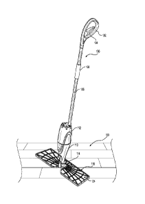
[0007] FIG. 1 is a perspective view of a spray mop according to one
embodiment of the
disclosure.
[0008] FIG. 2 is a right side view of the spray mop of FIG. 1.
[0009] FIG. 3 is a left side view of the spray mop of FIG. 1.
[0010] FIG. 4 is a rear view of the spray mop of FIG. 1.
[0011] FIG. 5 is a front view of the spray mop of FIG. 1.
[0012] FIG. 6 is a top view of the cleaning end of a spray mop according
to an
embodiment of the disclosure.
[0013] FIG. 7 is a bottom view of the cleaning end of shown in FIG. 6.
[0014] FIG. 8 is a bottom view of the cleaning end shown in FIG. 7 with a
cleaning pad
disposed on the cleaning end.
[0015] FIG. 9 is a perspective view of a spray mop according to one
embodiment of the
disclosure with the cleaning end in an inverted position with the top surface
of the cleaning
end disposed in contact with a surface to be cleaned.
DETAILED DESCRIPTION
[0016] Reference will now be made in detail to specific embodiments or
features,
examples of which are illustrated in the accompanying drawings. Wherever
possible,
corresponding or similar reference numbers will be used throughout the
drawings to refer to
the same or corresponding parts. Moreover, references to various elements
described herein,
are made collectively or individually when there may be more than one element
of the same
type. However, such references are merely exemplary in nature. It may be noted
that any
reference to elements in the singular may also be construed to relate to the
plural and vice-
versa without limiting the scope of the disclosure to the exact number or type
of such
elements unless set forth explicitly in the appended claims. The terms
configured and
configuration as used herein refer to a specified structural size and shape.
CA 3015275 2018-08-24
3
[0017] The invention is directed to a spray mop. The spray mop has a
structure suitable
for use as either a wet mop or a dry mop. When used as a wet mop, the spray
mop is able to
project a fluid, such as a cleaning solution, in front of the mop and onto a
surface for
cleaning. The spray mop can then be guided over the surface by the user to
clean the surface.
[0018] Referring to FIGS. 1-9, the spray mop 100 can include a handle
102, a trigger 104,
an external shaft 106, a grip 108, a spray housing 110, a bottle 112, a
multidirectional joint
114, and a cleaning end 116. The handle 102, which is disposed at or near the
proximal end
of the mop 100, can be used to grip and guide the spray mop 100 in a desired
direction. The
trigger 104, which is disposed in the handle 102, can be used to actuate a
pump mechanism to
activate the spray. The grip 108 can be coupled to the external shaft 106 to
provide a
secondary handhold. The spray housing 110 retains the bottle 112 and connects
the external
shaft 106 to the cleaning end 116. The bottle 112 is filled with a fluid for
cleaning a surface,
such as a floor 160 (FIG. 9). The bottle 112 is reusable and is removably
mounted to the
spray housing 110 so that it can be filled with a cleaning fluid. Fluid in the
bottle 112 is
communicated to a pump mechanism, which draws fluid from the bottle 112 and
provides a
pressurized fluid flow to a spray nozzle 120. The spray nozzle 120 sprays the
fluid onto the
floor. The multidirectional joint 114 provides freedom of movement in multiple
directions
between the spray housing 110 and the cleaning end 116 such that a user can
easily direct and
steer the cleaning end 116 along a desired path.
[0019] The spray housing 110 includes the nozzle 120 on its front
surface. The nozzle
120 is generally directed forward and downward so that fluid exiting the
nozzle 120 is
sprayed onto a surface in front of the cleaning end 116 of the spray mop 100.
[0020] The cleaning end 116 includes a plate frame 122 that is attached
to the
multidirectional joint 114. The multidirectional joint 114 is configured to
permit the plate
frame 122 to pivot such that either a lower face 124 or an upper face 126 of
the plate is
oriented to face the surface to be cleaned.
[0021] As discussed further below, the cleaning end 116 is sized and
shaped to receive a
cleaning pad 118 (FIG. 8) as is well known. The cleaning pad 118 can be any
suitable type
for any suitable surface to be cleaned, such as disposable or reusable
cleaning pads or
coverings (such as microfiber pads). The pad 118 may be made of synthetic or
natural
materials or combinations thereof. The cleaning pad 118 may be shaped by two
layers of
fabric. Each layer of fabric may have an outer, cleaning side and an inner
side. The layers are
placed adjacent one another with their inner sides in facing relation, and are
attached to one
CA 3015275 2018-08-24
4
another along at least three sides around their perimeter. The fourth side is
left at least
partially unattached to form an internal pocket. When the pad 118 is attached
to the cleaning
end 116 of the mop, the cleaning end pad, deck or plate 122 is placed in the
pocket to retain
the pad thereon. The pad or plate 122 can be flipped to expose either of the
two cleaning
sides to the floor.
[0022] The configuration of the plate 122 will now be set out in detail.
The plate 122 is a
framework connected to the multidirectional joint 114, such that the cleaning
end 116 is
permitted to pivot and move as noted above.
[0023] The plate 122, referring to FIGS. 6 and 7, is shaped generally as
a plate having
upper and lower faces, front and rear faces, and side faces. The upper and
lower faces may be
generally trapezoid in shape with the narrower width side oriented towards the
front or rear of
the mop, depending on the orientation of the plate 122, i.e., depending on
whether the upper
surface 126 is oriented upwardly toward the handle or downwardly away from the
handle.
However, the plate 122 may have other suitable shapes such as rectangular,
square or and any
suitable non-quadrilateral shapes, triangular, round, elliptical and the like.
[0024] The plate 122 includes a generally planar horizontal
configuration, when viewed
as shown in at least FIGS. 4 and 5. The plate 122 may include an upper surface
126 that is U-
shaped across the width W of the plate (i.e., the long axis of the plate) as
shown in FIG. 4.
The plate 122 may include an upper surface 126 that is concave such that at
least the lateral
outer side edges 128 thereof have a higher elevation than the center of the
plate, referring to
the depiction of the device as in FIG. 4, for example. The concavity may be
only defined
laterally across the width W of the plate 122 from side to side or the
concavity may be both
from side to side and the front to the back of the plate. In other words, the
plate 122 may have
a thickness that is minimum around the center of the plate 122, where the
connection 114 is
disposed, and increases in both directions towards the lateral sides of the
plate 122.
[0025] The plate 122 includes a lower surface 124, on the face opposite
of the upper
surface 126 of the plate, that is the mirror of the upper surface, in that the
lower surface has
an inverse U-shaped or a concave surface, wherein the center of the lower
surface has a
higher elevation than the lateral outer side edges 128. Since the shaft 106
terminates at joint
144 in the center of the plate 122, the act of pressing down on the handle 102
causes the
downward facing face to flatten out (if the plate is flexible) and downward
force to be exerted
on the center of the plate 122. Because of the concave shape of the surface
(124 or 126) that
is positioned in contact with the surface to be cleaned, i.e., the acting
surface, the downward
CA 3015275 2018-08-24
5
force tends to be higher on the surface at the radially outward periphery of
the plate 122 and
more particularly at the outer side edges 128. This is a significant
improvement over prior art
embodiments, where the down force tends to be concentrated in the center of
the cleaning end
and insufficient or a lesser reaction force from the floor is applied along
the outer portions of
the plate 122.
[0026] The plate 122 includes a framework with a border element 130 that
is disposed
about the peripheral boundary of the plate 122 and defines the outer boundary
or edge of the
plate. The border element 130 may be a continuous, uninterrupted band or strip
of material
that forms a vertical wall of varying height when the plate 122 is lying flat
on the floor. The
plate 122 also includes a plurality of web members 132 that interconnect the
center element
134 to the border element 130. The web members 132 are separate strips of
material that are
spaced apart by voids 158 in the plate. In other words, the web members 132
are discrete,
individual lengths of material that define voids therebetween. The web members
132 are
attached to each other where they intersect and where they terminate at one or
both of the
border element and the center element. The center element 134 surrounds and is
attached to
the joint 144.
[0027] The web members 132 include two sub-types of web members. The web
members
132 include a set of radially extending web members 136 that interconnect the
center element
134 to the border element 130. Each of the radially extending web members 136
extend
radially from the center element to the border element 130 in an arrangement
like wheel
spokes. The web members 132 include a set of concentric circular web members
138. The
concentric circular web members 138 are concentrically disposed about the
center element
134 and interconnect a front portion 140 of the border element 130 to a rear
portion 142 of
the border element. Where the radially extending web members 136 intersect the
concentric
circular web members 138 the web members 132 interconnect with each other, so
as to form
an interconnected web structure.
[0028] The web members 132 may be made of any suitable material, such as
plastic,
metal, and composite materials. The web members 132 may be configured to
provide a
selected amount of resilience or compliance such that the plate 122 conforms
to the surface
being cleaned. This capability also permits the plate 122 to flex and urges
the outer edges 128
against the surface to be cleaned, thus enhancing the cleaning function of the
mop 100. Also,
the ability to flex enhances the ability of the mop 100 to accommodate to non-
smooth floors,
such as tile and stone, for example. In other embodiments, the plate 122 is
relatively rigid,
CA 3015275 2018-08-24
6
which enhances the effectiveness of transferring the downforce applied through
the shaft 106
to the outer edges 128. The web members 132 also have the effect of reducing
weight of the
plate 122 by virtue of the presence of the voids 158 defined therebetween. The
configuration
of the web members 132 are adaptable to any "flip-mop" or "flat mop" device.
[0029] All references, including publications, patent applications, and
patents, cited
herein are hereby incorporated by reference to the same extent as if each
reference were
individually and specifically indicated to be incorporated by reference and
were set forth in
its entirety herein.
[0030] The use of the terms "a" and "an" and "the" and "at least one" and
similar
referents in the context of describing the invention (especially in the
context of the following
claims) are to be construed to cover both the singular and the plural, unless
otherwise
indicated herein or clearly contradicted by context. The use of the term "at
least one"
followed by a list of one or more items (for example, "at least one of A and
B") is to be
construed to mean one item selected from the listed items (A or B) or any
combination of two
or more of the listed items (A and B), unless otherwise indicated herein or
clearly
contradicted by context. The terms "comprising," "having," "including," and
"containing" are
to be construed as open-ended terms (i.e., meaning "including, but not limited
to,") unless
otherwise noted. Recitation of ranges of values herein are merely intended to
serve as a
shorthand method of referring individually to each separate value falling
within the range,
unless otherwise indicated herein, and each separate value is incorporated
into the
specification as if it were individually recited herein. All methods described
herein can be
performed in any suitable order unless otherwise indicated herein or otherwise
clearly
contradicted by context. The use of any and all examples, or exemplary
language (e.g., "such
as") provided herein, is intended merely to better illuminate the invention
and does not pose a
limitation on the scope of the invention unless otherwise claimed. No language
in the
specification should be construed as indicating any non-claimed element as
essential to the
practice of the invention.
[0031] Preferred embodiments of this invention are described herein,
including the best
mode known to the inventors for carrying out the invention. Variations of
those preferred
embodiments may become apparent to those of ordinary skill in the art upon
reading the
foregoing description. The inventors expect skilled artisans to employ such
variations as
appropriate, and the inventors intend for the invention to be practiced
otherwise than as
specifically described herein. Accordingly, this invention includes all
modifications and
CA 3015275 2018-08-24
7
equivalents of the subject matter recited in the claims appended hereto as
permitted by
applicable law. Moreover, any combination of the above-described elements in
all possible
variations thereof is encompassed by the invention unless otherwise indicated
herein or
otherwise clearly contradicted by context.
CA 3015275 2018-08-24