Note: Descriptions are shown in the official language in which they were submitted.
CA 03015340 2018-08-21
WO 2017/147068 PCT/US2017/018710
MICROFLOW RESTRICTOR ASSEMBLY
AND METHODS OF MAKING THE SAME
CROSS-REFERENCE TO RELATED APPLICATIONS
[0001] This application claims the benefit of priority of U.S. Provisional
Application Serial
No. 62/298,168, filed February 22, 2016, the entire contents of which are
incorporated herein by
reference.
FIELD OF THE INVENTION
[0002] The present invention relates generally to the field of flow
restrictors, and more
specifically to microflow restrictors useful in medical applications.
BACKGROUND OF THE INVENTION
[0003] Microflow restrictors are commonly used in the medical field in
conjunction with
infusion pump systems to regulate the flow of medicine and other fluids to a
patient. Microflow
restrictors are typically able to regulate fluid flow in the range of less
than 500 milliliters per
hour, but can regulate higher rates of flow if necessary. Typical pressures
under which infusion
pump systems operate are less than about 60 kPa.
[0004] Considerable difficulties with existing microflow restrictors are
recognized in the
prior art. Specifically, with regard to maintaining flow through the
restrictor over time, prior art
microflow restrictors are believed to be highly susceptible to seizing due to
the presence of
microparticulates and bubbles in the fluid. The small amount of fluid flowing
through the
restrictor and the minimal operating pressures of infusion pumps is believed
to provide
insufficient pressure to move or otherwise overcome the particulates or break
the bubbles and
permit fluid to continue to flow through the restrictor. To address this
issue, select prior art
microflow restrictors have been specifically designed to create multiple
tortuous paths for fluid,
such paths designed to break bubbles and permit particulates to be
circumvented by the fluid.
1
CA 03015340 2018-08-21
WO 2017/147068 PCT/US2017/018710
[0005] However, prior art flow restrictors are expensive to manufacture due
to the very small
fluid pathways utilized. Some existing flow restrictors are manufactured using
costly processing
and post-processing steps. In addition, existing flow restrictors suffer from
decreasing flow rates
over time due to micro leaks within the flow restrictors.
SUMMARY OF THE INVENTION
[0006] The inventors have discovered, unexpectedly in view of the prior
art, that triboelectric
charges created by the fluid flowing through the microflow restrictor impact
the flow of fluid
through the restrictor over time. By managing the triboelectric effects of the
fluid and microflow
restrictor, the microflow restrictor is able to consistently function as
intended over time.
Additionally, the unique configuration of the fluid pathway in the present
invention permits
better management of triboelectric effects while at the same time simplifying
manufacturing
processes and reducing manufacturing costs. Hence, the present invention
enables management
of very small amounts of fluid flow over time without significant interference
from triboelectric
effects in a microflow restrictor configuration that permits manufacturing in
a more cost-
effective manner.
[0007] The present invention is directed to a medical fluid microflow
assembly which
includes an assembly fluid inlet and an assembly fluid outlet. A mandrel
having an exterior
surface is positioned within a cavity of a housing so that at least a portion
of the exterior surface
of the mandrel is substantially parallel to at least a portion of an interior
surface of the cavity. At
least one protrusion extends from either the interior surface of the cavity or
the exterior surface
of the mandrel, each protrusion abutting either the exterior surface of the
mandrel or the interior
surface of the cavity to form a sealed fluid channel. The sealed fluid channel
may include a
channel inlet positioned proximate to the assembly fluid inlet and a channel
outlet positioned
proximate to the assembly fluid outlet.
[0008] The sealed fluid channel has a length and an average width and, in
certain
embodiments, the length of the channel may be greater than ten times the
average width of the
sealed fluid channel. The average width of the sealed fluid channel may be at
least 50 microns
and in some embodiments maybe wider than 50 microns. The sealed fluid channel
may have a
2
CA 03015340 2018-08-21
WO 2017/147068 PCT/US2017/018710
constant width along at least a portion of the length of the sealed fluid
channel, or may have a
width that varies along at least a portion of the length of the channel. In
certain embodiments,
the width of the sealed fluid channel may increase along at least a portion of
the length of the
channel so that the sealed fluid channel is widest proximate to the channel
outlet.
[0009] The exterior surface of the mandrel may be variously shaped and may
have a conical
shape so that the sealed fluid channel may extend about the exterior surface
of the mandrel in a
helical pattern.
[0010] In particular embodiments, a portion of the exterior surface of the
mandrel may be
planar. At least a portion of the interior surface of cavity may be configured
to be substantially
parallel to the planar portion of the exterior surface of the mandrel. In
configurations where at
least two portions of the exterior surface of the mandrel are planar, both
portions being
substantially parallel to at least a portion of the interior surface of the
cavity, a protrusion may be
positioned on each planar surface of either the mandrel or the cavity so that
at least two sealed
fluid channels are formed.
[0011] The protrusion may extend from either the planar portion of the
exterior surface of
the mandrel or the interior surface of the cavity. In some embodiments,
protrusions may extend
from the exterior surface of the mandrel and the interior surface of the
cavity.
[0012] The sealed fluid channel has an average height which is the average
distance between
the exterior surface of the mandrel and the interior surface of the cavity of
the housing in some
embodiments. The sealed fluid channel also has an average width, and in some
embodiments the
average width of the sealed fluid channel is at least the same as, e.g., at
least 3 times, at least 5
times, or at least 10 times, the average height of the sealed fluid channel.
In certain
configurations, the average height of the sealed fluid channel may be equal to
or greater than
about five (5) microns and less than about five hundred (500) microns. At
least one of the
surfaces which form the sealed fluid channel may have an average surface
roughness that is less
than about ten percent (10%), e.g., less than about five percent (5%), of the
average height of the
sealed fluid channel, and ideally, as smooth as possible.
3
CA 03015340 2018-08-21
WO 2017/147068 PCT/US2017/018710
[0013] The protrusion may include a first surface and a second surface, the
first and second
surfaces forming an apex which contacts either the exterior surface of the
mandrel or the interior
surface of the cavity to form the sealed fluid channel. In some configurations
the apex may be
formed as a radius, which may in certain configurations be greater than or
equal to 0.001
microns.
[0014] The sealed fluid channel may be at least partially formed from a
material that exhibits
a substantially neutral triboelectric charge when in contact with a saline or
glucose solution. To
achieve this, the sealed fluid channel may be at least partially formed from
polycarbonate.
Portions of the sealed fluid channel may also be formed from polysulfone,
acrylic, PVC, Nylon,
Polyethylene, Polypropylene polymers, or combinations of these materials with
polycarbonate.
[0015] The medical fluid microflow assembly may be configured so that the
sealed fluid
channel permits fluid to flow through the assembly fluid outlet at a flow rate
greater than about
0.01 ml per hour, and in some configurations at a flow rate of less than about
500 ml per hour.
[0016] In accordance with another aspect of the present invention, a method
for
manufacturing a medical fluid microflow assembly is provided. The method may
include
forming a medical fluid microflow assembly housing comprising a cavity, and
forming a
mandrel comprising an exterior surface. In addition, prior to hardening at
least one of the
material of the medical fluid microflow assembly housing or the mandrel, the
mandrel may be
positioned within the cavity of the medical fluid microflow assembly housing
such that at least
one partially-hardened protrusion extending from either an interior surface of
the cavity or the
exterior surface of the mandrel abuts either the exterior surface of the
mandrel or the interior
surface of the cavity to form a sealed fluid channel. The partially-hardened
material has a
greater capacity to deform and thereby compensate for geometric and
manufacturing variations,
forming a more perfect seal between microflow assembly housing and mandrel,
and decreasing
propensity for microleaks. After positioning the mandrel within the cavity of
the medical fluid
microflow assembly housing, the mandrel and/or the medical fluid microflow
assembly housing
are hardened either through time, temperature, chemical, or other means. In
one embodiment,
the medical fluid microflow assembly is assembled when all components are
fully hardened
except for the medical fluid microflow assembly housing which is partially-
hardened during
4
CA 03015340 2018-08-21
WO 2017/147068 PCT/US2017/018710
assembly. In another embodiment, only the mandrel is partially hardened during
assembly of the
medical fluid microflow assembly.
[0017] In another embodiment, the method includes achieving a desired flow
rate through
the microflow assembly. For example, the method may include loading a medical
fluid
microflow assembly housing having a cavity into a fixture, and applying a
curing adhesive on a
portion of the interior surface of the cavity of the housing between the
interior surface of the
cavity and the post. The method further may include monitoring an airflow rate
of a pressurized
gas or a pressure differential between the inlet and outlet, e.g. a vacuum at
the outlet, passing the
pressurized gas through the sealed fluid channel from the channel inlet to the
channel outlet, and
adjusting the pressing of the post against the mandrel based on the monitored
airflow rate. The
curing adhesive may then be cured when the measured airflow rate reaches a
target airflow rate.
BRIEF DESCRIPTION OF THE DRAWINGS
[0018] FIG. 1A is a perspective view of an infusion pump system utilizing
an embodiment of
a microflow assembly according to an aspect of the present invention.
[0019] FIG. 1B is another perspective view of an infusion pump system
utilizing an
embodiment of a microflow assembly according to another aspect of the present
invention.
[0020] FIG. 2A is a perspective exploded view of the microflow assembly of
FIG. 1A.
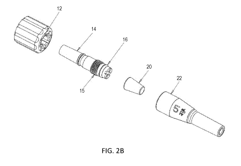
[0021] FIG. 2B is a perspective exploded view of another embodiment of the
microflow
assembly.
[0022] FIG. 3A is a perspective view of an embodiment of a microflow
assembly according
to the present invention.
[0023] FIG. 3B is a side view of the embodiment of the microflow assembly
depicted in FIG.
3A.
[0024] FIG. 4A is a cross-sectional view of the microflow assembly depicted
in FIG. 3B,
taken along line A-A.
CA 03015340 2018-08-21
WO 2017/147068 PCT/US2017/018710
[0025] FIG. 4B is a cross-sectional view of an embodiment of the microflow
assembly.
[0026] FIG. 4C is a cross-sectional view of the assembled microflow
assembly depicted in
FIG. 2B.
[0027] FIG. 5 is a side view of an embodiment of a fluid dowel useful in
the present
invention.
[0028] FIG. 6 is an end view of the fluid dowel depicted in FIG. 5.
[0029] FIG. 7 is a side view of an embodiment of a housing useful in the
present invention.
[0030] FIG. 8 is a cross-sectional view of the housing depicted in FIG. 7,
taken along line B-
B.
[0031] FIG. 9 is an enlarged view of an encircled portion of the housing
depicted in FIG. 8.
[0032] FIG. 10 is an enlarged view of an encircled portion of the housing
depicted in FIG. 9.
[0033] FIG. 11 is an enlarged view of an encircled portion of the microflow
assembly
depicted in FIG. 4A.
[0034] FIG. 12A is a side view of an embodiment of the mandrel.
[0035] FIG. 12B is a side view of another embodiment of the mandrel.
[0036] FIG. 12C is a side view of yet another embodiment of the mandrel.
[0037] FIG. 13A is a perspective view of still another embodiment of the
mandrel.
[0038] FIG. 13B is a top view of an alternate embodiment of the mandrel.
[0039] FIG. 13C is a cross-sectional view of the mandrel depicted in FIG.
13B.
[0040] FIG. 13D is a perspective view of a different embodiment of the
mandrel.
[0041] FIG. 13E is a cross-sectional view of another embodiment of the
mandrel.
6
CA 03015340 2018-08-21
WO 2017/147068 PCT/US2017/018710
[0042] FIG. 14 is a partial cross-sectional view of the mandrel and
housing.
[0043] FIG. 15 is a cross-sectional view of an embodiment of the microflow
assembly
positioned within the reservoir of an ambulatory infusion pump.
[0044] FIG. 16 is a flowchart illustrating an exemplary method of
manufacturing a
microflow assembly according to an aspect of the present invention.
[0045] FIG. 17 is a flowchart illustrating an exemplary method of achieving
a desired flow
rate through the microflow assembly according to an aspect of the present
invention.
[0046] FIG. 18 is a graph illustrating the benefits of manufacturing a
microflow assembly
with partially-hardened "green" components.
DETAILED DESCRIPTION
[0047] The invention will now be described with reference to one or more
embodiments
which are illustrated in the drawings. It is to be understood that the
detailed description is
provided by way of explanation of the invention and is not meant as a
limitation of the invention.
For instance, features illustrated and described as part of one embodiment may
be used on
another embodiment to yield a still further embodiment. It is intended that
the present invention
include these and other modifications and variations to the embodiments
described herein.
[0048] FIG. 1A illustrates ambulatory infusion pump system 110 for delivery
of fluids to a
patient. Ambulatory infusion pump system 110 typically includes reservoir 112,
a reservoir
support, and tubing 114 through which fluid from reservoir 112 flows.
Reservoir 112 also may
function as a pump and is typically a rubber or elastomeric bladder which is
designed to exert a
constant pressure on the contents of the pump during the infusion process.
Typical pressures in
the ambulatory infusion pump system can range of from about 20 kPa to about 60
kPa.
[0049] As shown in FIGS. 1A and 1B, a fluid inlet of microflow restrictor
10 may be
connected to medical tubing 114 to receive fluid from reservoir 112. Fluid
passes through
microflow restrictor 10 and exits through a fluid outlet of microflow
restrictor 10 into needle
7
CA 03015340 2018-08-21
WO 2017/147068 PCT/US2017/018710
assembly 113 to flow to the patient as shown in FIG. 1A or into medical tubing
116 to flow to
the patient as shown in FIG. 1B.
[0050] Microflow assembly 10 may be configured to engage and retain various
articles at its
assembly fluid inlet 28 and assembly fluid outlet 26 (both shown in FIG. 3A),
such as medical
tubing, luer lock connectors, as well as any other of a multitude of
mechanisms available to form
fluid pathways.
[0051] Microflow restrictor assembly 10 may be utilized to restrict the
flow of fluids to the
patient. Microflow restrictor assembly 10 may be connected to reservoir 112
via medical tubing
114 and may be connected to a patient using a variety of mechanisms. For
example and as
shown in FIG. 1A, microflow restrictor assembly 10 may be connected at one end
to medical
tubing 114 and at its other end to needle assembly 113 configured to engage an
established
intravenous site of a patient. In other configurations and as shown in FIG.
1B, microflow
restrictor assembly 10 may be connected to medical tubing 116 which may have
needle assembly
113 connected to its other end. Optionally, multiple microflow restrictor
assembles may be used
in a fluid path between reservoir 112 and the patient. For example, in FIG.
1B, fluid flows from
reservoir 112 into medical tubing 114, through microflow restrictor assembly
10 into medical
tubing 116, through a second microflow restrictor assembly, into needle
assembly 113 and to the
patient. Other articles may be utilized in place of needle assembly 113,
including catheters, luer
lock fittings, or other specialized fittings.
[0052] Referring to FIGS. 2A-4B, a medical fluid microflow assembly is
shown therein.
Microflow assembly 10 includes assembly fluid inlet 28 and assembly fluid
outlet 26, which are
fluidly connected so that fluid entering assembly fluid inlet 28 passes
through microflow
assembly 10 and exits microflow assembly 10 through assembly fluid outlet 26.
Assembly fluid
inlet 28 may, in some embodiments and as shown in FIGS. 4A and 4B, be
positioned in housing
22. Assembly fluid outlet 26, in some embodiments and as shown in FIGS. 4A and
4B, may be
positioned in post 14.
[0053] FIG. 2A is an exploded view of an embodiment of microflow assembly
10 which
includes housing 22, mandrel 20, dowel 18, seal 16, post 14, and connector 12.
Other
8
CA 03015340 2018-08-21
WO 2017/147068 PCT/US2017/018710
embodiments of microflow assembly 10 may be configured so that selected
elements, such as
mandrel 20 and dowel 18 are formed as a single piece. For example, housing 22
and connector
12 may be formed as a single piece, which may also include seal 16. Post 14,
seal 16, dowel 18,
and mandrel 20 may also be formed as a single piece. In certain embodiments,
selected pieces
may be omitted for ease of manufacturing.
[0054] As seen in FIG. 2A, mandrel 20 is positioned within housing 22 and
may include
cavity 70, end 68, and exterior surface 66. Dowel 18 may be useful in
embodiments where
mandrel 20 is formed with central cavity 70. Body 50 of dowel 18 may be
positioned within
cavity 70 of mandrel 20 and may be useful to provide support to mandrel 20.
Body 50 of dowel
18 may occupy only a portion of central cavity 70.
[0055] Post 14 is configured to move dowel 18 and mandrel 20 into cavity 80
within housing
22. In select embodiments, post 14 and dowel 18 may be formed as a single
element.
Depending on the suitability for specific manufacturing processes, post 14,
seal 16, dowel 18,
and connector 12 may be formed as one or multiple elements. For example, post
14 and dowel
18 may be formed as a single element. In other embodiments, post 14, dowel 18,
and connector
12 may be formed as a single element. Post 14, mandrel 20, and dowel 18 may be
formed as a
single element or may be joined via adhesive, ultrasonic welding, screws or
snap-together
features.
[0056] Seal 16 may be formed as a part of post 14 or may be separately
formed and
positioned between post 14 and interior surface 86 of housing 22. For example,
seal 16 may be
positioned within detent 46 of post 14 such that seal 16 is in contact with an
exterior surface of
post 14 and interior surface 86 of housing 22. Seal 16 functions to ensure
that fluid is
transmitted only through passage 42 and prevents fluid bypassing the
restricted flow channel
which meters the appropriate flow of fluid through microflow assembly 10. Seal
16 also helps
prevent adhesive used to join post 14 to interior surface 86 of housing 22
from interfering with
the flow of fluid through microflow restrictor assembly 10. Seal 16 may be
formed from any of
a variety of materials including silicone, rubber or other suitable materials.
In certain
embodiments, post 14 and seal 16 may be formed as a single element, and seal
16 may be co-
9
CA 03015340 2018-08-21
WO 2017/147068 PCT/US2017/018710
molded with post 14, mandrel 20, dowel 18, or housing 22. Post 14, seal 16,
and connector 12
may also be formed as a single element.
[0057] FIG. 2B is an exploded view of another embodiment of microflow
assembly which
includes housing 22, mandrel 20, seal 16, post 14, and connector 12. As seen
in FIG. 2B, post
14 may include threaded feature 15. In addition, housing 22 may include a
spiral groove and
post 14 may include a spiked portion. Seal 16 may be over cast molded.
[0058] FIG. 3A shows an embodiment of microflow assembly 10 as assembled
and depicts
assembly fluid outlet 26 which is positioned in post 14. Assembly fluid inlet
28, shown in FIG.
4, is positioned in housing 22. FIG. 3B illustrates a side view of the
assembled microflow
assembly 10 of FIG. 3A.
[0059] As shown in FIGS. 3A and 3B, exterior surface 30 of connector 12 may
include
features to enhance its ease of use, such as indentations 32. Indentations 32,
or other gripping
features may be variously formed such as, for example, ribs, knurling or
simply a rough surface
texture.
[0060] Connector 12 includes opening 34 which may extend through connector
12. Threads
36 may be formed into interior surface 35 of opening 34, to permit a source of
fluid to be
releasably engaged to microflow assembly 10. Luer lock fittings and snap-fit
connections are
particularly well-suited for use in conjunction with connector 12.
[0061] As shown in FIGS. 4A and 4B, housing 22 further includes end 78
which may be
positioned adjacent to connector 12. Connector 12, in selected embodiments,
may include
recessed surface 38 and shoulder 40 which are configured to engage housing 22.
As shown in
FIG. 4B, post 14 and connector 12 may be designed so that connector 12 snaps
onto, or is
otherwise mechanically connected to, post 14.
[0062] End 78 of housing 22, which is adjacent to outlet portion 74, abuts
recessed surface
38 of connector 12. Shoulder 40 of connector 12 may extend around at least a
portion of outlet
portion 74 of housing 22. In certain embodiments, housing 22 and connector 12
may be press-fit
together or may be secured by adhesive or other joining processes such as
ultrasonic welding,
CA 03015340 2018-08-21
WO 2017/147068 PCT/US2017/018710
retention features, or fasteners. As depicted in the microflow assembly of
FIG. 4B, housing 22
may simply abut connector 12 and be secured in position by other elements of
microflow
assembly 10. In particular embodiments, housing 22 and connector 12 may be
integrally formed
as a single element.
[0063] The embodiment of the microflow assembly depicted in FIG. 4B shows
mandrel 20 is
positioned within cavity 80 of housing 22, mandrel 20 having no cavity and
being in contact
with post 14. Mandrel 20 and post 14 may be formed as a single element or may
be joined by
adhesive, retention mechanisms, ultrasonic welding and the like.
[0064] As shown in FIGS. 5 and 6, dowel 18 may further include disk 52
having
circumference 64, lower surface 54 which may be positioned adjacent to end 68
of mandrel 20.
Disk 52 may include upper surface 56 upon which may be positioned at least one
boss 58 and, in
some embodiments, a plurality of bosses 58. Upper surfaces 60 of the each boss
58 may contact
post 14.
[0065] FIGS. 4A-4C and 7-10 depict housing 22 useful in the present
invention. Housing 22
includes outlet portion 74 and inlet portion 76. In the embodiment depicted in
FIGS. 7 and 8,
assembly fluid inlet 28 is positioned proximate to inlet portion 76 of housing
22. Exterior
surface 73 of housing 22 may be variously formed to suit the particular needs
of the user. The
exterior of the housing may be configured to enable a user to easily and
securely grasp housing
22. Information regarding the characteristics of microflow assembly 10 may be
imprinted on
housing 22.
[0066] As shown in FIG. 8, housing 22 includes interior surface 86 which
forms cavity 80.
Cavity 80 may have areas such as inlet portion 84 and transition portion 82.
Interior surface 86
of housing 22 may be variously shaped, and may have some portions which are
planar, curved,
conical, or other shapes.
[0067] As shown in FIG. 4A, in select embodiments, assembly fluid inlet 28
may be
positioned adjacent to cavity 80, and cavity 80 may have inlet portion 84.
Fluid enters
microflow assembly 10 through assembly fluid inlet 28 in housing 22.
11
CA 03015340 2018-08-21
WO 2017/147068 PCT/US2017/018710
[0068] As best shown in FIG. 11, exterior surface 66 of mandrel 20 is
positioned proximate
to interior surface 86 of cavity 80 of housing 22.
[0069] Post 14, shown in FIGS. 2A and 4A-4C, has inlet end 48. Passage 42
in post 14
extends from inlet end 48 to assembly fluid outlet 26. Inlet end 48 of post 14
is positioned in
contact with bosses 58 of dowel 18 or mandrel 20. As seen in FIGS. 2A and 4A,
post 14 may
also include collar 44 extending outwardly from and encircling at least a
portion of post 14
proximate to inlet end 48. Upon assembly of post 14 into housing 22, collar 44
may be
configured so that a gap is formed between either collar 44 and interior
surface 86 of cavity 80 or
the exterior surface of post 14 and interior surface 86 of cavity 80. Adhesive
may be used to
secure post 14 to housing 22 and, in select embodiments, to mandrel 20. A
wicking-type
adhesive may be used to fill the gap and secure the components together. Such
an adhesive may
be applied after post 14 has been positioned within housing 22.
[0070] The gap between post 14 and housing 22 may range from about .01 mm
to about 1.25
mm, and may be about 0.075 mm in selected embodiments.
[0071] As seen in FIG. 4C, which is a cross-sectional view of the microflow
assembly
depicted in FIG. 2B in an assembled configuration, post 14 may include
threaded feature 15.
Threaded feature 15 may engage with at least a portion of interior surface 86
of housing 22.
[0072] Referring to FIGS. 8-13B, at least one protrusion 90 is positioned
on either interior
surface 86 of cavity 80 of housing 22, or on exterior surface 66 of mandrel
20. FIG. 8 shows
protrusion 90 positioned on interior surface 86, in the area in which mandrel
20 will be
positioned. Protrusion 90 may extend along a substantial length of housing 22,
and in some
embodiments may extend beyond the length of mandrel 20. This permits
flexibility in the
process by which microflow assembly 10 is constructed by enabling a wider
variation in the
positioning of mandrel 20 within housing 22.
[0073] FIGS. 9 and 10 show an embodiment of protrusion 90 in greater
detail. Protrusion 90
may be formed as a ramp having a width W and a height H at its highest end.
Protrusion 90 may
include first surface 92 and second surface 94, first and second surfaces 92,
94 forming apex 96
as shown in FIG. 10. Protrusion 90 may extend along interior surface 86 or
exterior surface 66
12
CA 03015340 2018-08-21
WO 2017/147068 PCT/US2017/018710
of mandrel 20 for a length sufficient so that it forms at least two complete
wraps about the
circumference of interior surface 86.
[0074] FIG. 11 shows protrusion 90 which abuts exterior surface 66 of
mandrel 20. As seen
therein, sealed fluid channel 100 is formed between interior surface 86,
exterior surface 66, and
protrusion 90. In the embodiment shown in FIGS. 8-11, sealed fluid channel 100
forms a helical
path for fluid through microflow restrictor assembly 10.
[0075] In particular embodiments, protrusion 90 has a length that extends
in a substantially
continuous helix on at least a portion of interior surface 86 or exterior
surface 66. Protrusion 90
may be positioned on such surface in different manners. For example, the
distance between the
successive wraps of protrusion 90, or pitch of protrusion 90, may increase or
decrease with
respect to the direction of flow of fluid through the assembly. The pitch of
protrusion 90 may
also be uniform or non-uniform along the length of the surface. For example
and as illustrated in
FIG. 12A, protrusion 90 is positioned on exterior surface 66 of mandrel 20,
and the pitch of
protrusion 90 decreases in the direction of flow. The pitch of protrusion 90
shown in FIG. 12B
increases with respect to the direction of fluid flow. FIG. 12C illustrates a
non-uniform
positioning of protrusion 90 on surface 66. FIGS. 12A-12C are illustrative
only as protrusion 90
may form many more wraps about surface 66.
[0076] Many configurations of protrusion 90 are suitable for use in the
present invention,
including protrusions having cross-sectional shapes which are triangular,
elliptical, orthogonal,
or circular. However, it is desirable to select a cross-sectional area at apex
96 (shown in FIG.
10) which will focus the compressive load during assembly of mandrel 20 and
housing 22, and
permit controlled deformation of the small total area at apex 96. This permits
local stresses at
apex 96 to exceed the plastic limit of the material from which protrusion 90
is formed.
[0077] The local deformation of protrusion 90 is preferably configured to
avoid the creation
of hoop stresses in housing 22 sufficient to cause cracking. The materials
selected for protrusion
90, housing 22, and mandrel 20 will impact the robustness of microflow
assembly 10 to
cracking. Additionally, the angle of exterior surface 66 of mandrel 20 will
impact the resistance
of housing 22 to cracking. In some embodiments, an angle of seven degrees
(fourteen degree
13
CA 03015340 2018-08-21
WO 2017/147068 PCT/US2017/018710
included angle) permits mandrel 20 to be self-locking while not producing
excessive hoop
stresses. Angles of between five and nine degrees (ten and eighteen degree
included angles) are
also suitable for use in the present invention.
[0078] As described above, sealed fluid pathway 100 of the present
invention is formed by
interior surface 86 of housing 22 and exterior surface 66 of mandrel 20. The
particular
configuration of mandrel 20 and housing 22 may be variously structured to
achieve sealed fluid
pathway 100. In some embodiments, interior surface 86 of housing 22 provides a
tapered
conical recess into which mandrel 20 is positioned. Exterior surface 66 of
mandrel 20 may be
formed as a corresponding tapered conical surface from which protrusions 90
extend.
[0079] As shown in FIGS. 13A-13D, exterior surface 66 of mandrel 20 may at
least partially
include a planar surface of a wedge. These types of mandrels 20 will be
suitable for use in
housings 22 having at least a portion of their interior surface 86 formed as
an angled planar
surface.
[0080] FIG. 13A shows mandrel 20 formed as a wedge upon which protrusion 90
is
positioned. Interior surface 86 of housing 22 should be shaped so that at
least a portion of
interior surface 86 is substantially parallel to and spaced apart from
exterior surface 66 of
mandrel 20 when mandrel 20 is inserted into housing 22.
[0081] As shown in FIG. 13A, protrusion 90 is positioned on mandrel 20 so
that two sealed
fluid channels 100 are created when wedge-shaped mandrel 20 is engaged with
housing 22.
One, two, or more sealed fluid channels 100 may be included in microflow
assembly 10.
[0082] Sealed fluid channel 100 may encircle mandrel 20 or be positioned on
a single side of
mandrel 20. FIGS. 13A-13D depict mandrels 20 having at least one planar
surface upon which
protrusion 90 is formed. Protrusion 90 of FIG. 13A forms two sealed fluid
channels 100 which
move the fluid back and forth across a single surface of mandrel 20. The
embodiment in FIGS.
13B and 13C positions protrusion 90 on a single surface of mandrel 20, however
sealed channel
100 is formed as a spiral, the fluid exiting the spiral through aperture 71
and channel 72. FIG.
13D depicts mandrel 20 as a wedge, having protrusion 90 positioned on two
surfaces of mandrel
20. In some embodiments and as shown in FIG. 13E, protrusion 90 may be
positioned upon
14
CA 03015340 2018-08-21
WO 2017/147068 PCT/US2017/018710
mandrel 20 having a rectangular cross-section. Wedge 21 may be utilized to
move mandrel 20
into the proper position within housing 22.
[0083] Protrusion 90 may be configured specifically for the particular
surface upon which it
is positioned. For example, protrusion 90 which, as shown in FIG. 8, extends
along interior
surface 86 of cavity 80, may extend beyond the length of mandrel 20 when
mandrel 20 is
positioned within housing 22.
[0084] It is desirable that the height of protrusions 90 are preferably
uniform.
[0085] In some embodiments, the angles of interior surface 86 of housing 22
and exterior
surface 66 of mandrel 20 should be selected so that their uppermost portions
present a similarly
tapered conical form which enabled mandrel 20 and housing 22 to become self-
locking. To
achieve this, the taper angle should be essentially at or slightly below the
self-clinching angle for
the particular material that is being utilized to form protrusions 90 on
mandrel 20 and housing
22. For example, polycarbonate materials have a self-clinching angle that is
approximately 15
degrees (a 30 degree included angle). Utilizing such a self-locking feature
permits a wider range
of bonding processes to be successfully utilized on microflow assembly 10.
[0086] Referring to FIG. 14, fluid within cavity 80 passes beyond
protrusion 90 and into
sealed fluid channel 100. The configuration of mandrel 20 and housing 22
creates a rectangular
entrance to sealed fluid housing 100. Bubbles in the fluid are likely to come
into contact with an
edge of the rectangular entrance, as illustrated in FIG. 14. The rectangular
entrance to sealed
fluid channel 100 may create pressure points which assist in breaking bubbles
such as bubble
106 contained in the fluid.
[0087] The configuration of sealed fluid channel 100 may encourage laminar
flow, which
may be helpful in maintaining an air/water correlation of flow. Fluid flows
through sealed fluid
channel 100, exiting proximate to dowel 18. Seal 16 prevents the fluid from
exiting housing 22
except through passage 42, which ends at assembly outlet 26. Different
configurations of
microflow restrictor 10 may also include alternate configurations of post 14,
connector 12, and
housing 22.
CA 03015340 2018-08-21
WO 2017/147068 PCT/US2017/018710
[0088] Sealed fluid channel 100 may, in particular embodiments, have a
height that is greater
than about five (5) microns and less than about five hundred (500) microns and
a width that is
greater than about fifty (50) microns and less than about six thousand (6000)
microns. The
height of sealed fluid channel 100 may be adjusted by the distance mandrel 20
is inserted into
housing 22. The fluid flow through sealed fluid channel 100 may be selected by
manufacturing
sealed fluid channel 100 with a specific height H, a specific width W, and a
specific length L.
[0089] Referring to FIG. 15, the microflow restrictor assembly may be
formed as an integral
component of an ambulatory infusion pump. As shown in FIG. 15, ambulatory
infusion pump
1500 may include microflow restrictor assembly 10' incorporated at least
partially within
reservoir 112'. The components of microflow restrictor assembly 10' may be
constructed similar
to microflow restrictor assembly 10 of, e.g., FIG. 2A. For example, mandrel
20' of FIG. 15
corresponds with mandrel 20 of FIG. 2A, seal 16' of FIG. 15 corresponds with
seal 16 of FIG.
2A, and post 14' of FIG. 15 corresponds with post 14 of FIG. 2A. Post 14' may
be positioned
within a tube socket. Microflow restrictor assembly 10' includes housing 22',
such that mandrel
20', seal 16', and post 14' are positioned within housing 22' to form a sealed
fluid channel as
described above.
[0090] Microflow restrictor assembly 10' may include fill inlet 1502 having
a fluid channel
extending therethrough from fill inlet 1502 to one-way valve 1504 disposed
within reservoir
112'. Reservoir 112' may receive fluid via fill inlet 1502, and one-way valve
1504 may prevent
fluid from exiting reservoir 112' through fill inlet 1502. One-way valve 1504
may be any one-
way valve known in the art. Microflow restrictor assembly 10' may include
inlet 1508 which
may permit fluid from reservoir 112' to flow through microflow restrictor
assembly 10' and
ultimately through medical tubing 116'. In addition, reservoir 112' may be
secured on microflow
restrictor assembly 10' via ring clamp 1506.
[0091] Certain embodiments of microflow restrictor 10 may be assembled in
equipment
configured to flow air through microflow restrictor 10 from assembly inlet 28
to assembly outlet
26 while a load, either static or impulse, is applied to post 14 which moves
mandrel 20 into the
appropriate position in housing 22.
16
CA 03015340 2018-08-21
WO 2017/147068 PCT/US2017/018710
[0092] Pressure applied to post 14 is used to adjust the rate of fluid flow
through microflow
assembly 10. Flow rates between 500 ml/hour and 0.5 ml/hour are attainable,
and in certain
embodiments flow rates between 0.5 ml/hour and 0.01 ml/hour may be attained.
As pressure is
applied to post 14, the outlet end of post 14 presses on surfaces 60 of bosses
58 which are
positioned on dowel 18. Lower surface 54 of dowel 18 moves mandrel 20 further
into cavity 80.
In selected embodiments, protrusion 90 may be compressed or deformed to reduce
the height H
of sealed fluid channel 100.
[0093] Adjustment of the flow rate and sealing of sealed fluid channel 100
depend on the
deformation of protrusion 90 and the surface against which it is deformed. The
configuration of
apex 96 of protrusion 90 may vary widely, however the smaller area of apex 96
will permit local
stresses to form at apex 96 which may exceed the plastic limit of the material
from which the
protrusion is formed.
[0094] To enable the deformation of protrusion 90 positioned on interior
surface 86 of
housing 22, the material selected to form protrusion 90 may be softer than the
material used to
form mandrel 20. In contrast, the material used to form mandrel 20 may be
selected so that it is
softer than the material used to form protrusion 90. In this situation,
mandrel 20 will deform
around protrusion 90. The same material may be used to form both protrusion 90
and mandrel
20, permitting both to be deformed to form an air-tight seal.
[0095] As air flows through microflow assembly 10, the air flow is measured
and, in many
embodiments of the present invention, the configuration of sealed fluid
channel 100 provides for
an air/water correlation which will permit accurate calibration of the device.
Any potential leaks
through seal 16 or other portions of the device will occur after the fluid has
passed through
sealed fluid channel 100, enabling an accurate flow measurement to be
achieved.
[0096] An adhesive such as a UV curing adhesive may be applied between post
14 and
housing 22 prior to insertion into housing 22 and application of the load to
post 14. The desired
flow rate through microflow assembly 10 is achieved before the adhesive is
cured. The
adhesive may also be applied after mandrel 20 has been inserted to the correct
position within
housing 22 and the desired flow rate achieved, although bumping or other
handling may alter the
17
CA 03015340 2018-08-21
WO 2017/147068 PCT/US2017/018710
position of post 14 or mandrel 22 and hence the flow rate. Once the adhesive
cures, the
dimensions of sealed fluid channel 100 are fixed.
[0097] Injection molding is an economical and accurate method by which
portions of
microflow restrictor 10 may be manufactured. During the injection molding
process, an
injection mold will wear and protrusion 90 may increase in height due to this
change. However,
the method of assembly accommodates this potential change in the manufacturing
process and
enables microflow restrictor 10 to be assembled to a pre-set flow rate in the
same manner. The
method of assembly also accommodates variations in the manufacture of the
components.
[0098] Referring now to FIG. 16, method 1600 of manufacturing microflow
restrictor
assembly 10 is described. At step 1602, medical fluid microflow assembly
housing 22 having
cavity 80 is formed from a material, e.g., plastic, using a machine, e.g.,
injection molding
machine. After injection molding, plastics are uncured in the sense that they
are partially-
hardened. In the case of polycarbonate, the hardening/curing process takes 3-5
days. Prior to
that, the uncured plastic is slightly softer and referred to as "green," e.g.,
partially-hardened.
Other "green" plastics may be used that may be hardened by application of
energy, e.g., heat
(thermoset), UV, etc. In addition, hardening of the "green" plastic may be
prevented or delayed
by, e.g., refrigeration, freezing, or a chemical agent. Accordingly, the
"green" plastic may
subsequently be hardened/cured by reversing the hardening prevention, e.g., by
applying heat or
another chemical agent.
[0099] Similarly, at steps 1604, 1606, and 1608, mandrel 20 having exterior
surface 66, post
14 having assembly fluid outlet 26, and connector 12 having opening 34
extending therethrough,
are formed from a material, e.g., plastic, using a machine, e.g., injection
molding machine. At
step 1610, mandrel 20 is positioned within cavity 80 of housing 22 such that
at least one
partially-hardened uncured protrusion 90 extending from either interior
surface 86 of cavity 80
or exterior surface 66 of mandrel 20, as described above, abuts either
exterior surface 66 of
mandrel 20 or interior surface 86 of cavity 80 to form a sealed fluid channel.
The sealed fluid
channel includes a channel inlet positioned proximate to fluid inlet 28 and a
channel outlet
positioned proximate to fluid outlet 26, thereby reducing decrease of flow
rate over time within
the medical fluid microflow assembly.
18
CA 03015340 2018-08-21
WO 2017/147068
PCT/US2017/018710
[00100] The inventors determined, unexpectedly, that using partially-hardened
uncured plastic
to form protrusion 90 improved consistency in flow rate over time and
prevented or minimized
the decrease in flow rate over time ("sagging") which may result from micro
leaks between the
protrusions and the smooth surface of either exterior surface 66 of mandrel 20
or interior surface
86 of housing 22.
[00101] The
inventors discovered that the slightly lower hardness allows the spiral
feature,
e.g., protrusion 90, to deform more, and to the point, enough to form an
impermeable seal. In
one embodiment, protrusion 90 on interior surface 86 of housing 22 is "green,"
whereas exterior
surface 66 of mandrel 20 is hardened plastic. In another embodiment, exterior
surface 66 of
mandrel 20 is "green," whereas protrusion 90 on interior surface 86 of housing
22 is hardened
plastic. In yet another embodiment, both protrusion 90 on exterior surface 66
of mandrel 20 and
interior surface 86 of housing 22 are "green". In contrast to the industry
standard to wait until
plastic cures before assembly, the inventors discovered that assembling
components of a medical
fluid microflow assembly prior to hardening reduces rate of change of flow
rate. For example,
the partially-hardened components assembled together may cure to fill in
undesirable microgaps
between components resulting from the manufacturing process.
[00102] Sealing between housing 22 and mandrel 20 is critical to providing
consistent flow
rates due to the sagging phenomenon described above. Other methods to seal may
include, e.g.,
laser, photon, solvent, vibration, ultrasonic, etc.
[00103] At step 1612, post 14 is pressed against mandrel 20 within cavity 80
of housing 22
such that assembly fluid outlet 26 of post 14 is in fluid communication with
the channel outlet.
At step 1614, connector 12 is secured to housing 22 such that at least a
portion of post 14 is
positioned within opening 34 of connector 12. As described above, connector 12
may be
designed so that connector 12 snaps onto, or is otherwise mechanically
connected to, post 14.
[00104] In conventional practice, most plastic parts are made in large batches
at external
vendors and warehoused before assembly, thus providing adequate time for the
plastic to harden.
However, in accordance with an aspect of the present invention, the uncured
components are
assembled in a relatively quick time (e.g., less than 12 hours after forming
each component, less
19
CA 03015340 2018-08-21
WO 2017/147068 PCT/US2017/018710
than 8 hours after forming each component, less than 6 hours after forming
each component),
thereby reducing sagging. At step 1616, housing 22, mandrel 20, post 14, and
connector 12 are
hardened/cured. Cure time may be a function of the particular plastic. For
example, the cure
time/time to harden of PolyCarbonate is 3-5 days, e.g., 36-60 hours.
[00105] While steps 1610-1616 describe assembling multiple partially hardened
components
to form the microflow restrictor assembly, it should be understood that not
all components need
be partially hardened. For example, in one embodiment, the microflow
restrictor assembly is
assembled when all components are fully hardened except for housing 22 which
is partially-
hardened during assembly. In another embodiment, only the mandrel is partially
hardened
during assembly of the medical fluid microflow assembly. After assembly,
housing 22 is
allowed to harden/cure, thereby reducing sagging.
[00106] Referring now to FIG. 17, an exemplary method of achieving a desired
flow rate
through microflow assembly 10 is described. Method 1700 may be performed using
a microflow
assembly machine. For example, a microflow assembly machine may include a
controller, e.g.,
computer, a motorized linear actuator, a fixture, a flow meter, e.g., a mass
flow meter, and a UV
light. At step 1702, microflow restrictor assembly housing 22 is loaded into
the fixture of the
microflow assembly machine.
[00107] At step 1704, a curing adhesive, e.g., UV cure epoxy, is applied on
interior surface 86
of housing 22. The adhesive may be applied to a portion of interior surface 86
of housing 22 in
the cavity between interior surface 86 and post 14. The adhesive, e.g., Dymax
1160-m-sv01,
may include a fluorescing element such that visual or machine vision
inspection is easier. In one
embodiment, the adhesive may be applied to interior surface 86 of housing 22
before housing 22
is loaded into the fixture. In yet another embodiment, the adhesive may be
applied to interior
surface 86 of housing 22 after the components of microflow restrictor assembly
10 are cured and
microflow restrictor assembly 10 is fixed.
[00108] At step 1706, mandrel 20 is positioned within cavity 80 of housing 22
such that at
least one partially-hardened protrusion 90 extending from either interior
surface 86 of cavity 80
CA 03015340 2018-08-21
WO 2017/147068 PCT/US2017/018710
or exterior surface 66 of mandrel 20 abuts either exterior surface 66 of
mandrel 20 or interior
surface 86 of cavity 80 to form a sealed fluid channel as described above.
[00109] At step 1708, post 14 is pressed against mandrel 20 within cavity 80
of housing 22 to
compress microflow restrictor assembly 10 by, e.g., the motorized linear
actuator or any
mechanism well known in the art that may slowly, but consistently increase
compression force
such as hydraulic or rotary actuators. As described above, using partially-
hardened plastic,
protrusion 90 may deform more, producing a good seal and preventing sagging.
[00110] At step 1710, the airflow rate of pressurized gas, e.g., air or N2,
is monitored via the
flow meter prior to being passed through the sealed fluid channel at step
1712. In one
embodiment, differential pressure across the sealed fluid channel may be
monitored via the flow
meter. The flow meter provides a near instantaneous value of the air flow rate
through the sealed
fluid channel. Since the airflow rate correlates with the fluid flow rate,
microflow restrictor
assembly 10 may be tuned to a desired fluid flow rate by adjusting the
compression of microflow
restrictor assembly 10 at step 1714 until the airflow rate monitored at step
1708 reaches a target
airflow rate.
[00111] When the target airflow rate is achieved, and accordingly the desired
fluid flow rate
through microflow restrictor assembly 10, at step 1716, the adhesive is cured,
e.g., by activating
the UV light, which cures the adhesive and fixes the location of post 14, and
accordingly, the
location of mandrel 20 within housing 22. As will be understood by one skilled
in the art, the
adhesive may be cured by any curing means well known in the art.
[00112] Referring now to FIG. 18, a graph illustrating the benefits of
manufacturing
microflow assembly 10 with uncured "green" components is described. As
described above,
using components formed from partially-hardened uncured plastic to manufacture
microflow
restrictor assembly 10 results in improved consistency in flow rate over time
and reduces or even
prevents sagging within medical fluid microflow assembly 10. FIG. 18
illustrates the results of
an experiment conducted whereby the flow rate of air through a microflow
assembly
manufactured with hardened plastic components shown by line 1802 was compared
with the
21
CA 03015340 2018-08-21
WO 2017/147068 PCT/US2017/018710
flow rate of air through a microflow assembly manufactured with uncured
"green" plastic
components shown by line 1804.
[00113] As shown in FIG. 18 and as seen in Table 1 below, the airflow rate
through the
microflow assembly manufactured with uncured "green" plastic components was
consistent over
a 40 hour time period (approximately 3 mL/hour). In contrast, as shown in FIG.
18 and as seen
in Table 2 below, the airflow rate through the microflow assembly manufactured
with hardened
plastic components decreased over the 40 hour time period (from 2.27 ml/hour
to 1.83 mL/hour).
Green Plastic Sample
airflow (sccm) time (hr) flow rate (mL/hr)
7.16 1.00 3.045
3.00 3.024
4.99 2.989
6.98 3.006
18.30 3.031
40.12 3.016
% Change: 0.93
Table 1
Cured Plastic Sample
airflow (sccm) time (hr) flow rate (mL/hr)
7.21 1.00 2.278
3.00 2.193
8.00 2.005
14.04 2.002
18.08 1.977
22.08 1.950
30.08 1.880
40.08 1.832
% Change: 19.59
Table 2
22
CA 03015340 2018-08-21
WO 2017/147068 PCT/US2017/018710
[00114] The inventors have discovered, unexpectedly in view of the prior art,
that the seizing
phenomenon is not due to bubbles and microparticulates, but rather to
triboelectric charges
created by the fluid flowing through the microflow restrictor. Specifically,
the inventors noted
that the flow of saline through a restrictor was uninterrupted despite the
increased potential for
microparticulate clogging while medical grade water for injection exhibited a
consistently slower
rate of flow over time.
[00115] Triboelectric charging is a type of contact electrification in
which certain materials
come into contact with each other and exchange electrons. This effect is
amplified as the fluid
and the material of the microflow restrictor assembly are in sliding contact.
This causes the
materials to become electrically charged. The polarity and strength of the
charges that are
produced will differ, based on the specific materials and surface roughness of
those materials,
and the distance between the surfaces. By managing the triboelectric effects
of the combined
fluid and microflow restrictor, the microflow restrictor is able to
consistently function as
intended over time.
[00116] Managing the triboelectric charge created by a fluid flowing through
sealed fluid
pathway 100 will necessitate careful consideration of the optimal materials
from which mandrel
20 and housing 22 are formed, as well as configuring the surface roughness of
each of the
surfaces which form sealed fluid channel 100. The materials may be selected to
match specific
medical fluids. For example, polycarbonate material may be selected for
medical saline or
glucose solution, including additional medications.
[00117] The surface roughness used herein is the average surface roughness Ra
which
characterizes the surface based on the absolute value of the vertical
deviations of the roughness
profile from the mean line and is calculated as follows, where y is the height
of the deviation
from the mean line:
L
Cmdd
[00118] In certain embodiments that are selected for particular
applications, interior surface
86 and exterior surface 66 preferably have a surface roughness of between
about 0.012 microns
23
CA 03015340 2018-08-21
WO 2017/147068 PCT/US2017/018710
and about 5 microns. The surface roughness is desirably less than ten percent
(10%), e.g., less
than five percent (5%), of the height H of sealed fluid channel 100. While not
every surface
which forms sealed fluid channel 100 will contact fluid, it is preferred in
some embodiments that
all surfaces which form sealed fluid channel 100 have a surface roughness
which significantly
reduces any triboelectric effect from the fluid flowing across the surface.
The roughness of
surfaces 66 and 86 may also differ from one another.
[00119] While many materials may be used to form microflow restrictor assembly
10,
including metals and glass, polymers are generally an economical and adaptable
material for use.
A wide range of polymers is suitable for use in the present invention, and
should be selected to
correspond to the particular use of the microflow assembly. Polymers such as
polycarbonate,
polysulfones and acrylic plastics such as poly(methyl methacrylate) (PMMA),
PVC (Poly Vinyl
Chloride), Nylon, Polyethylene, and polypropylene are useful as materials for
forming portions
of the microflow restrictor assembly. In particular, medical grade
polycarbonate may be used for
many potential applications of the microflow assembly. In some embodiments,
the polymer
selected may be matched to a particular fluid to reduce the triboelectric
effects for a particular
application of the microflow restrictor assembly. In some embodiments, the
material chosen
should exhibit a minimal amount of creep.
[00120] It should be appreciated by those skilled in the art that various
modifications and
variations may be made to features of the medical fluid microflow restrictor
described herein
without departing from the scope and spirit of the invention. It is intended
that the invention
include all such variations.
24