Note: Descriptions are shown in the official language in which they were submitted.
CA 03015514 2018-08-22
DEGRADABLE MATERIAL TIME DELAY SYSTEM AND METHOD
CROSS REFERENCE TO RELATED APPLICATIONS
[0001] This application claims priority benefit from U.S. Application No.
15/090,963, filed April 5, 2016, which is a continuation-in-part of U.S.
Application Nos.
15/053,417 and 15/053,534, both filed February 25, 2016.
FIELD OF THE INVENTION
[0002] The present invention generally relates to restriction plug elements in
a
wellbore. Specifically, the invention attempts to utilize a reactive fluid
that reacts with a
degradable mechanical element for a known time delay and initiates a
detonating event
inside a restriction plug element.
PRIOR ART AND BACKGROUND OF THE INVENTION
Prior Art Background
[0003] In oil and gas extraction applications, there is a need to have a
certain
length of time delay between pressure triggered events such that the system
can be tested
at a pressure before the next event could proceed. This system cannot be
controlled with
any other means besides the application of pressure. Prior art system means of
fluid
restriction uses a complex system of microscopic passages that meter fluid.
Therefore,
there is a need for non-expensive simple and flexible component flow
restriction systems.
[0004] Inside a tandem in a gun string assembly, a transfer happens between
the
detonating cords to detonate the next gun in the daisy chained gun string.
Detonation can
be initiated from the wireline used to deploy the gun string assembly either
electrically, by
pressure activation or by electronic means. In tubing conveyed perforating
(TCP) as there
is no electric conductor, pressure activated percussion initiation is used to
detonate. TCP is
used to pump up to a tubing pressure that reaches a certain pressure enabling
a firing head
to launch a firing pin. Subsequently, the firing pin starts the percussion
initiator which
starts the detonation cord. There
- I -
CA 03015514 2018-08-22
WO 2017/146850 PCT1US2017/014622
is a need to delay the launching of a firing pin by a predetermined time in
certain instances so
that tests can be conducted or a hang fire condition may be detected on a
previous gun.
[0005] In tandem systems there is a single detonating cord passing
through the guns.
There are no pressure harriers. However, in select fire systems (SFS) there is
a pressure isolation
switch between each gun. Each gun is selectively fired though its own
detonation train. A
detonator feeds off each switch. When the lower most perforating gun is
perforated, pressure
enters the inside of the gun. When the first gun is actuated, the second
detonator gets armed when
the pressure in the first gun switch moves into the next position actuating a
firing pin to enable
detonation in the next gun. All guns downstream are isolated from the next gun
by the pressure
barrier.
[0006] Spool valves are directional control valves that are used as
wellbore tools. They
allow fluid flow into different paths from one or more sources. They usually
consist of a spool
inside a cylinder which is mechanically or electrically controlled. The
movement of the spool
restricts or permits the flow, thus it controls the fluid flow. There are two
fundamental positions
of directional control valve namely normal position where valve returns on
removal of actuating
force and other is working position which is position of a valve when
actuating force is applied.
However, prior art spool valves do not have a control mechanism with a pre-
determined delay to
switch from normal position to a working position.
[0007] It is known that well fluids vary in the chemical nature and are
not always the
same composition. However, the temperature of the well is often defined or can
be manipulated
to achieve a pre-determined temperature. Most time delay elements currently
used comprise
complex mechanisms and are often expensive. Therefore, there is a need for a
time delay tool
that can use a known fluid or an unknown fluid inside a well at a known
temperature such that a
known degradable element can react and degrade in the known fluid at the known
temperature
for a known amount of time so that a pre-determined time may be achieved to
trigger a
mechanism in a device.
[0008] In many instances a single wellbore may traverse multiple hydrocarbon
formations that are otherwise isolated from one another within the Earth. It
is also frequently
desired to treat such hydrocarbon bearing formations with pressurized
treatment fluids prior to
CA 03015514 2018-08-22
WO 2017/146850 PCT1US2017/014622
producing from those formations. In order to ensure that a proper treatment is
performed on a
desired formation, that formation is typically isolated during treatment from
other formations
traversed by the wellbore. To achieve sequential treatment of multiple
formations, the easing
adjacent to the toe of a horizontal, vertical, or deviated welibore is first
perforated while the other
portions of the casing are left unperforated. The perforated zone is then
treated by pumping fluid
under pressure into that zone through perforations. Following treatment a plug
is placed adjacent
to the perforated zone. The process is repeated until all the zones are
perforated. The plugs are
particularly useful in accomplishing operations such as isolating perforations
in one portion of a
well from perforations in another portion or for isolating the bottom of a
well from a wellhead.
The purpose of the plug is to isolate some portion of the well from another
portion of the well.
[0009] Subsequently, production of hydrocarbons from these zones
requires that the
sequentially set plugs be removed from the well, In order to reestablish flow
past the existing
plugs an operator must remove and/or destroy the plugs by milling, drilling,
or dissolving the
plugs,
[0010] Additionally, frac plugs can be inadvertently set at undesired
locations in the
wellbore casing creating unwanted constrictions. The constrictions may latch
wellbore tools that
are run for future operations and cause unwanted removal process. Therefore,
there is a need to
prevent premature set conditions caused by conventional frac plugs.
[0011] The steps comprised of setting up a plug, isolating a hydraulic
fracturing zone,
perforating the hydraulic fracturing zone and pumping hydraulic fracturing
fluids into the
perforations are repeated until all hydraulic fracturing zones in the wellbore
casing are processed.
When all hydraulic fracturing zones are processed, the plugs are milled out
with a milling tool
and the resulting debris is pumped out or removed from the wellbore casing.
Hydrocarbons are
produced by pumping out from the hydraulic fracturing stages.
[0012] The milling step requires that removal/milling equipment be run
into the well
on a conveyance string which may typically be wire line, coiled tubing or
jointed pipe. The
process of perforating and plug setting steps represent a separate "trip" into
and out of the
wellbore with the required equipment. Each trip is time consuming and
expensive. In addition,
the process of drilling and milling the plugs creates debris that needs to be
removed in another
CA 03015514 2018-08-22
WO 2017/146850 PCT1US2017/014622
operation. Therefore, there is a need for isolating multiple hydraulic
fracturing zones without the
need for a milling operation. Furthetmore, there is a need fur positioning
restrictive plug
elements that could be removed in a feasible, economic, and timely manner
before producing
gas.
Deficiencies in the Prior Art
[0013] The prior art as detailed above suffers from the following
deficiencies:
* Prior art systems do not provide for a known degradable element that can
react and
degrade in a known fluid at a known temperature for a known amount of time so
that
a pre-determined time may be achieved to trigger a mechanism in a device.
= Prior art systems do not provide for a low cost configurable time delay
flow
restriction element that is commonly available.
* Prior art systems do not provide for a predictable time delay.
* Prior art systems do not provide for a cost effective time delay solution
that are
independent of the wellbore
= Prior art systems require bulky and expensive hydraulics.
* Prior art systems require expensive electronics that have difficulty
functioning at
downhole temperatures.
O Prior art systems do not provide for isolating multiple hydraulic
fracturing zones
without the need for a milling operation.
* Prior art systems do not provide for positioning restrictive elements
that could be
removed in a feasible, economic, and timely manner.
* Prior art systems cause undesired premature preset conditions preventing
further
wellbore operations.
[0014] While some of the prior art may teach some solutions to several of
these
problems, the core issue of a predictable time delay with known fluids at pre-
determined
temperatures has not been addressed by prior art.
CA 03015514 2018-08-22
WO 2017/146850 PCT11JS2017/014622
BRIEF SUMMARY OF THE INVENTION'
System Overview
[0015] The present invention in various embodiments addresses one or more of
the
above objectives in the following manner. A detonating restriction plug
element wellbore casing
includes a hollow passage in the restriction plug element that receives a
detonating assembly
coupled to a mechanical restraining element, and a space for containing a
reactive fluid. The
mechanical restraining element undergoes a change in shape for a pre-
determined time delay due
to a chemical reaction when the reactive fluid in the space such as wellbore
fluids comes in
contact with the restraining element. A firing pin in the detonating assembly
is released when the
restraining elements changes shape and releases the restraint on the firing
pin. The firing pin
contacts a detonator in the detonating assembly and causes a detonating event
such that the
restriction plug element fragments. The amount of the pre-determined time
delay is determined
by factors that include the reactive fluids, concentration of the reactive
fluids, geometry and size
of the mechanical restraining element.
Method Overview
[0016] The present invention system may be utilized in the context of an
overall
detonating method, wherein the detonating restriction plug element as
previously described is
controlled by a method having the following steps:
(1) deploying the restriction plug element into the wellbore casing and
isolating a
stage to block fluid communication;
(2) fracturing the stage;
(3) initiating a chemical reaction between the mechanical restraining
element and the
reactive fluid;
(4) progressing the chemical reaction for a pre-determined time delay and
changing a
physical property of the mechanical restraining element;
(5) releasing the firing pin after elapse of the time delay; and
(6) initiating a detonating event.
CA 03015514 2018-08-22
WO 2017/146850 PCT/US2017/014622
[00171 Integration of this and other preferred exemplary embodiment methods in
conjunction with a variety of preferred exemplary embodiment systems described
herein in
anticipation by the overall scope of the present invention.
BRIEF DESCRIPTION OF THE DRAWINGS
[0018] For a fuller understanding of the advantages provided by the
invention,
reference should be made to the following detailed description together with
the accompanying
drawings wherein:
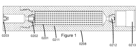
10019] FIG. 1 illustrates a cross-section overview diagram of downhole
wellbore time
delay tool according to an exemplary embodiment of the present invention.
1:0020] FIG. 2 illustrates a cross-section overview diagram of downhole
wellbore time
delay tool with an energetic device and a firing pin according to an exemplary
embodiment of the
present invention.
[0021] FIG. 3A-3D illustrates a cross-section view of downhole wellbore
time delay
tool with an energetic device and a firing pin describing an initial set up,
actuation position, a
degradation position, and a triggering position according to an exemplary
embodiment of the
present invention.
[0022] FIG. 3E-3E1 illustrates a cross-section view of downhole wellbore
time delay
tool with an energetic device and a firing pin with a shear pin restraint
describing an initial set
up, actuation position, a degradation position, and a triggering position
according to an
exemplary embodiment of the present invention.
[0023] FIG. 4A illustrates a perspective view of a downhole wellbore
time delay tool
with an energetic device and a firing pin according to an exemplary embodiment
of the present
invention.
[0024] FIG. 4B illustrates a perspective view of a downhole wellbore
time delay tool
with an energetic device and a firing pin with a shear pin restraint according
to an exemplary
embodiment of the present invention.
CA 03015514 2018-08-22
WO 2017/146850 PCT1US2017/014622
[0025] FIG. 5A-5D illustrates a cross-section view of downhole wellbore
time delay
tool with an energetic device and a firing pin and a spring loaded device
describing an initial set
up, actuation position, a degradation position, and a triggering positions
according to an
exemplary embodiment of the present invention.
[0026] FIG. 6 illustrates a perspective view of a downhole wellbore time
delay tool.
with an energetic device and a firing pin and a spring loaded device according
to an exemplary
embodiment of the present invention.
[0027] FIG, 7A-7D illustrates a cross-section view of downhole wellbore
time delay
tool with a spool valve describing an initial set up, actuation position, a
degradation position, and
a triggering positions according to an exemplary embodiment of the present
invention.
[0028] FIG. 7E-7F illustrates a cross-section view of downhole wellbore
time delay
tool with a spool valve and a tensile member according to an exemplary
embodiment of the
present invention.
[0029] FIG. 8 illustrates a perspective view of a dm,viihole 1,vellbore
time delay tool
with a spool valve according to an exemplary embodiment of the present
invention.
[0030] FIG, 9A-9D illustrates a cross-section view of downhole wellbore
time delay
tool with a firing pin and a switch describing an initial set up, actuation
position, a degradation
position, and a triggering position according to an exemplary embodiment of
the present
invention.
[0031] FIG, 10 illustrates a perspective view of a downhole wellbore
time delay tool
with a -firing pin and a switch according to an exemplary embodiment of the
present invention,
[0032] FIG. 11 illustrates a cross section view of a downhole wellbore
time delay tool
with a dissolvable plug according to an exemplary embodiment of the present
invention.
[0033] FIG. 12 illustrates an exemplary flow chart for a time delay
method operating
in conjunction with a downhole wellbore time delay tool according to an
embodiment of the
present invention.
CA 03015514 2018-08-22
WO 2017/146850 PCT11JS2017/014622
[0034] FIG. 13 illustrates a preferred exemplary flowchart embodiment of
a time delay
firing method in conjunction with a downhole wellbore time delay tool that is
integated into an
energetic device used in TCP operation according to an embodiment of the
present invention.
[0035] FIG. 14 illustrates an exemplary Time vs Temperature curve for
calculating a
time delay based on a known fluid and known restraining element according to
an embodiment
of the present invention.
[0036] FIG. 15 illustrates an exemplary predictable time delay flowchart
operating in
conjunction with a predictable downhole time delay tool according to an
embodiment of the
present invention.
[0037] FIG. 16A illustrates a cross section view of a detonating
restriction plug
element with a detonating assembly according to an exemplary embodiment of the
present
invention.
[0038] FIG. 16B illustrates another cross section view of a detonating
restriction plug
element with a detonating assembly according to an exemplary embodiment of the
present
invention.
[0039] FIG. 16C illustrates a cross section view of a detonating
restriction plug
element with a detonating assembly without a reservoir and a pressure
actuating device according
to an exemplary embodiment of the present invention.
[0040] FIG. 17 illustrates a flowchart embodiment of a detonating method
operating in
conjunction with a detonating restriction plug element according to an
exemplary embodiment of
the present invention.
OBJECTIVES OF THE INVENTION
[0041] Accordingly, the objectives of the present invention are (among
others) to
circumvent the deficiencies in the prior art and affect the following
objectives:
* Provide for a known degradable element that can react and degrade in a known
fluid
at a known temperature for a known amount of time so that a pre-determined
time
may be achieved to trigger a mechanism in a device.
CA 03015514 2018-08-22
WO 2017/146850 PCT11JS2017/014622
O Provide for a low cost configurable time delay flow restriction element
that is
commonly available,
O Provide for a predictable time delay,
e Provide for a cost effective time delay solution that is independent of
the wellbore
fluids,
a Provide for a tubing conveyed perforating gun with a delay mechanism which
provides a known delay interval between pressuring the tubing to a second
predetermined level and the actual firing of the perforating gun.
O Provide for a delay means to move a firing pin holder out of locking
engagement with
a firing pin, to release firing pin, after a predetermined time interval.
e Provide for portable and inexpensive hydraulics for a time delay tool.
a Provide for an inexpensive time delay tool that functions reliably at
downhole
temperatures.
4, Provide for a time delay tool suitable for wireline conveyed, coil tubing
conveyed,
casing conveyed or pump down.
O Provide for isolating multiple hydraulic fracturing zones without the
need for a
milling operation.
O Provide for positioning restrictive elements that could be removed in a
feasible,
economic, and timely manner,
* Provide for tools that prevent undesired premature preset conditions that
hinder
further µvellbore operations.
[0042] While these objectives should not be understood to limit the teachings
of the
present invention, in general these objectives are achieved in part or in
whole by the disclosed
invention that is discussed in the following sections. One skilled in the art
will no doubt be able
to select aspects of the present invention as disclosed to affect any
combination of the objectives
described above.
CA 03015514 2018-08-22
WO 2017/146850 PCT11JS2017/014622
Description of the Presently Preferred Exemplary Embodiments
[0043] While this invention is susceptible of embodiment in many
different forms,
there is shown in the drawings and will herein be described in detailed
preferred embodiment of
the invention with the understanding that the present disclosure is to be
considered as an
exemplification of the principles of the invention and is not intended to
limit the broad aspect of
the invention to the embodiment illustrated.
[0044] The numerous innovative teachings of the present application will
be described
with particular reference to the presently preferred embodiment, wherein these
innovative
teachings are advantageously applied to the particular problems of a hydraulic
time delay system
and method. However, it should be understood that this embodiment is only one
example of the
many advantageous uses of the innovative teachings herein. In general,
statements made in the
specification of the present application do not necessarily limit any of the
various claimed
inventions. Moreover, some statements may apply to some inventive features but
not to others.
Preferred Exemplary Downhole We['bore Time Delay Tool Intearated into an
Enemetic
Device (0200 - 06001
[0045] As generally illustrated in FIG. 1 and FIG. 2 (0200), a downhole
wellbore time
delay tool (0210) for use in a wellbore casing comprises a reservoir (0211)
for containing a
reactive fluid (0201), an actuating device (0202) such as a rupture disk, a
mechanical restraining
element (0203) such as a nut and mechanically connected to a wellbore device
such as an
energetic device (0220) with firing pin (0204), a percussion initiator (0205),
a booster (0206) and
a detonating cord (0207). A detailed view of the wellbore tool (0210) is
illustrated in FIG, 1. The
entire tool (0200) may be piped into the casing string as an integral part of
the string and
positioned where functioning of the tool is desired or the tool may be
deployed to the desired
location with TCP, CT or a wire line. The wellbore may be cemented or not. The
fluid in the
reservoir (0211) is held at an initial position by the actuating device
(0202), such as a rupture
disk, The tool mandrel is machined to accept the actuating device (0202) (such
as rupture discs)
that ultimately controls the flow of reactive fluid (0201). The fluid
reservoir (0211) may be
further installed in within a fluid holding body (0208). The fluid holding
body (0208) may be
operatively connected to a body (0209) of the energetic device (0220). In one
embodiment, the
rated pressure of the actuating device may range from 500 PSI to 15000 PSI.
-10-
CA 03015514 2018-08-22
WO 2017/146850 PCT11JS2017/014622
[0046] 'The reservoir (0211) may be in fluid communication with the mechanical
restraining element via the actuation device (0202). Alternatively, the
reactive fluid may be
directly in fluid communication with the mechanical restraining element via
the actuation device
(0202) without a reservoir. For example, the mechanical restraining element
may not be in fluid
communication initially with any fluid. When the pressure in the wellbore
casing increases to
actuate the actuating device, wel.lbore fluids may enter and react with the
mechanical restraining
element. It should be noted that the reservoir to contain a reactive fluid may
not be construed as a
limitation A pressure port (0213) may be attached to another end of the
reservoir through
another actuating device (0212). The reservoir (0211) may be a holding tank
that may be
positioned inside a fluid holding body (0208) of a well casing. The volume of
the reservoir may
range from 25 ml to 5 liters. The material of the reservoir may be chosen so
that the reactive fluid
inside the reservoir does not react with the material of the reservoir and
therefore does not
corrode or erode the reservoir (0211). According to a preferred exemplary
embodiment, the
material of the reservoir may be selected from a group comprising: metal,
ceramic, plastic,
degradable, long teiiii degradable, glass, composite or combinations thereof.
The reservoir may
also be pressurized so that there is sufficient flow of the reactive fluid
towards the restraining
element, The actuation device (0202) may be a reverse acting rupture disk that
blocks fluids
communication between the reactive fluid and the restraining element. The
actuation device
(0212) ruptures or actuates when a pressure in the wellbore through the
pressure port (0213)
exceeds a rated pressure of the actuating device (0212). After the actuating
device (0212) rupture,
the pressure acting through the pressure port (0213) may act on the fluid
which further acts on
the actuating device (0202). When the pressure of the fluid acting on the
actuation device (0202)
exceeds a rated pressure of the actuating device (0202), the reactive fluid
(0201) flows through
and enters a chamber and comes in contact with the restraining element (0203).
According to
another preferred exemplary embodiment the actuating device is an electronic
switch that is
actuated by a signal from a device storing a stored energy.
[0047] The pressure on the actuation device (0202) may be ramped up to the
rated
pressure with pressure from the reactive fluid. The reactive fluid (0201) is
configured to react
with the mechanical restraining element (0203) at a temperature expected to be
encountered in
the wellbore. According to a preferred exemplary embodiment a physical
property change in the
-11-
CA 03015514 2018-08-22
WO 2017/146850 PCT11JS2017/014622
restraining element may occur at a pre-determined temperature expected to be
encountered in the
wellbore casing. According to a further preferred exemplary embodiment the pre-
determined
temperature ranges from 25 C ¨ 250 C. The mechanical restraining element
(0203) may be a nut,
a shear pin, or a holding device that degrades as the reaction takes place.
Upon further
degradation, the mechanical restraining element (0203) may release a restraint
on the energetic
device (0220) and enable the entire pressure or stored energy to act on an end
of the energetic
device (0220).
[0048] According to a preferred exemplary embodiment the reactive fluid is
selected
from a group comprising: fresh water, salt water, KCL, NaC1,1-1CL, or
hydrocarbons.
[0049] The energetic device (0220) may be operatively connected to the
mechanical
restraining element via threads, seals or a connecting element. The tool
mandrel may be
machined to accept the wellbore reservoir, the actuating device and the
wellbore device such as a
firing pin assembly. hi some instances, the mechanical restraining element may
be a nut that may
be screwed or attached to a counterpart in the wellbore device. In other
instances the restraining
element may be a tensile member. The wellbore device may be an energetic
device (0220) with a
firing pin (0204) as illustrated in FIG, 2 (0200).
[0050] According to a preferred exemplary embodiment, when a stored energy,
such as
a pressure from a fluid, is applied on the firing pin assembly, the actuating
device (0202) is
actuated and the reactive fluid (0201) from the reservoir (0211) comes into
contact with the
mechanical restraining element (0203) and enables a physical property change
in the mechanical
restraining element such that the stored energy applied on the wellbore device
is delayed by a
pre-determined time delay while the mechanical restraining element undergoes
the physical
property change. The physical property change may enable the restraining
element to change
shape for a pre-determined period of time. The physical property may be
strength, ductility or
elasticity. In tubing conveyed perforating gun with a delay mechanism, a known
delay interval
between pressuring the tubing to a second pre-determined level and the actual
firing of the
perforating gun may be achieved by the pre-determined time delay. In a select
fire system, a delay
means, to move a firing pin holder out of locking engagement with a firing pin
to release the
firing pin, may be achieved by the predetermined time interval. 5. The firing
pin (0204) may
contact a percussion detonator/initiator (0205) that connects to a
bidirectional booster (0206),
-12-
CA 03015514 2018-08-22
WO 2017/146850 PCT11JS2017/014622
The bidirectional booster (0206) may accept a detonation input from the
detonator. The
detonating cord (0207) may be initiated in turn by the booster (0206). When
the tiring pin is
actuated after the mechanical restraint (0203) is released, the firing pin
(0204) may contact a
percussion detonator (0205) and in turn initiate a detonator through a booster
(0206) and a.
detonating cord (0207).
[0051] According to a preferred exemplary embodiment, the stored energy
is applied
from a spring, According to another preferred exemplary embodiment, the stored
energy is
applied from a pressure from a fluid and a seal. According to a further
preferred exemplary
embodiment, the stored energy is applied from a magnetic field. According to
yet another
preferred exemplary embodiment, the stored energy is applied from a weight.
[0052] According to a preferred exemplary embodiment, the pre-determined time
delay ranges from 1 hour to 48 hours. According to a more preferred exemplary
embodiment, the
pre-determined time delay ranges from 2 days to 14 days. According to a most
preferred
exemplary embodiment, the pre-determined time delay ranges from .01 seconds to
1 hour.
[0053] According to a preferred exemplary embodiment, the chemical reaction
may be
an exothermic reaction that gives off heat. The energy needed to initiate the
chemical reaction
may be less than the energy that is subsequently released by the chemical
reaction. According to
another preferred exemplary embodiment, the chemical reaction may be an
endothermic reaction
that absorbs heat. The energy needed to initiate the chemical reaction may be
greater than the
energy that is subsequently released by the chemical reaction.
[0054] The rate of the chemical reaction may be accelerated or retarded
based on
factors such as nature of the reactants, particle size of the reactants,
concentration of the
reactants, pressure of the reactants, temperature and catalysts. According to
a preferred
exemplary embodiment, a catalyst may be added to alter the rate of the
reaction. According to a
preferred exemplary embodiment, the material of the restraining element may be
selected from a
group comprising: mixture of aluminum, copper sulfate, potassium chlorate, and
calcium sulfate,
iron, magnesium, steel, plastic, degradable, magnesium-iron alloy, particulate
oxide of an alkali
or alkaline earth metal and a solid, particulate acid or strongly acid salt,
or mixtures thereof. The
catalyst may be selected from a group comprising salts. According to a
preferred exemplary
-13-
CA 03015514 2018-08-22
WO 2017/146850 PCT11JS2017/014622
embodiment, the material of the restraining element may be selected from a
group comprising:
metal, non-metal or alloy.
[0055] According to a preferred exemplary embodiment the mechanical
restraining
element is a restrictive plug element. For example, the restriction plug
element may be a ball or a
plug that is used to isolate pressure communication between zones or stages in
a well casing.
[0056] According to a preferred exemplary embodiment the pre-determined time
delay
is determined by concentration of the reactive fluids. According to another
preferred exemplary
embodiment the pre-determined time delay is determined by reaction rate of the
reactive fluids
with the mechanical restraining element. According to yet another preferred
exemplary
embodiment the pre-determined time delay is determined by reaction time of the
reactive fluids
with the mechanical restraining element. According to a further preferred
exemplary embodiment
the pre-determined time delay is determined by masking a contact area of the
mechanical
restraining element. According to a further preferred exemplary embodiment the
pre-determined
time delay is determined by masking a total area of the mechanical restraining
element in contact
with the mechanical restraining element.
[0057] According to a preferred exemplary embodiment the shape of the
mechanical
restraining element is selected from a group comprising: square, circle, oval,
and elongated.
[0058] A sealed cap may seal the exposed end of the reservoir to
physically protect the
reservoir from undesired wellbore conditions.
[0059] According to an alternate preferred embodiment, a multi stage
restraining
element comprising a blocking member and a restraining member may further
increase a time
delay. For example, mechanical restraining element (0203) may be coupled with
a blocking
member that may have a different composition and reaction time with the fluid
in the reservoir.
The blocking member may react with the fluid for a period of time and may
restrict fluid access
to the mechanical restraining element for a pre-determined period of time. It
should be noted that
the multi stage restraining element may not limited to a blocking member and a
restraining
element. Any number of blocking members and restraining elements may be used
in combination
to achieve a desired time delay. The reaction times and therefore the time
delays of each of the
- I 4-
CA 03015514 2018-08-22
WO 2017/146850 PCT/US2017/014622
bonding members with the fluid may be characterized at various temperatures
expected in the
wellbore.
[0060] In another preferred exemplary embodiment, the reservoir may be filled
with
vvellbore fluids. For example, the reservoir may be empty when deployed into
the wellbore and
later filled with wellbore fluids. A time vs temperature chart for the
restraining element may be
characterized with different compositions of wellbore fluids expected in the
wellbore at
temperatures expected in the wellbore casing. Alternatively, the fluid
reservoir may be partially
filled with the known fluid and wellbore fluids may fill the remaining portion
of the reservoir.
The reservoir may be filled with the known fluid, wellbore fluids or a
combination thereof The
mechanical restraining element may comprise one or more material types that
react and have
different degradation rates in one or more fluid types. The desired time delay
may be achieved
with a combination of fluid types and restraining element material types.
[0061] The present exemplary embodiment is generally illustrated in more
detail in
FIG. 3A (0300), FIG. 3B (0310), FIG. 3C (0320), FIG. 3D (0330), wherein the
downhole
wellbore delay tool is deployed inside a wellbore casings FIG. 3A-3D generally
illustrates
different positions of a firing pin assembly (0304). The positions include an
initial set up position
(0300), an actuation position (0310), a degradation position (0320) and a
triggering position
(0330). The entire tool may be piped into the casing string as an integral
part of the string and
positioned where functioning of the tool is desired. In one exemplary
embodiment, the tool may
be a firing pin assembly that is positioned where detonation, perforation of a
formation and fluid
injection into a formation is desired. The tool may be installed in either
direction with no change
in its function. A detailed view of the tool in the initial set up position is
shown in FIG.3 (0300)
where in the fluid in the reservoir is held by the actuating device (0302).
When ready to operate,
the pressure is increased for example with TCP. The tool then moves to the
actuation position
(0310), when pressure acting on the actuating device (0302) exceeds its rated
pressure, the
actuation device ruptures and enables reactive fluid in the fluid reservoir
(0301) to enter the
adjacent chamber and contacts the restraining element. Subsequently, after
elapse of a pre-
determined time delay, the restraining element degrades or changes shape due
to the chemical
reaction as illustrated in the degradation position in HG. 3C (0320), In the
triggering position
(0330), the firing pin (0304) in the energetic device is triggered as the
restraining element (0303)
-15-
CA 03015514 2018-08-22
WO 2017/146850 PCT11JS2017/014622
no longer holds or restrains the firing pin (0304) due to change of shape or
strength. The entire '
stored energy may be applied to move the firing pin and contact a
bidirectional booster, after the
pre-determined time delay in the degradation position. The stored energy may
be applied by
pressure and seal, magnetic field, a weight, a spring or combination thereof
[0062] FIG,4A (0400) generally illustrates a perspective view of the
downhole delay
tool with a firing pin as the wellbore device.
[0063] Similar to FIGS. 3A-3D, a downhole delay tool with a firing pin
and a shear
= pin restraint is generally illustrated in FIGS. 3E-3H. As generally
illustrated in more detail in
FIG. 3E (0350), FIG. 3F (0360), FIG. 3G (0370), FIG. 311 (0380), wherein the
downhole
wellbore delay tool is deployed inside a wellbore casing. FIG. 3E-3H generally
illustrates
different positions of a tiring pin assembly (0324) restrained by a shear pin
(0325) in addition to
a mechanical restraining element (0323). The positions include an initial set
up position (0350),
an actuation position (0360), a degradation position (0370) and a triggering
position (0380). A
detailed view of the tool in the initial set up position is shown in FIG.3E
(0350) wherein the fluid
in the reservoir is held by the actuating device (0322). When ready to
operate, the pressure is
increased for example with TCP. The tool then moves to the actuation position
(0360), when
pressure acting on the actuating device (0322) exceeds its rated pressure, the
actuation device
ruptures and enables reactive fluid in the fluid reservoir (0321) or well
fluids from the wellbore
casing to enter the adjacent chamber and contacts the restraining element.
Subsequently, after
elapse of a pre-determined time delay, the restraining element degrades or
changes shape due to
the chemical reaction as illustrated in the degradation position in FIG, 3G
(0370). In the
triggering position (0380), the firing pin (0324) in the energetic device is
triggered as the
restraining element (0323) no longer holds or restrains the firing pin (0324)
and the shear pin
(0325) due to change of Shape or a physical property. According to a preferred
exemplary
embodiment, the shear pins provide additional control, when the time delay
enables, but it would
need an active input to finally fire, FIG.4B (0410) generally illustrates a
perspective view of the
downhole delay tool with an energetic device and a firing pin and a shear pin
restraint
mechanism as the wellbore device. The mechanical restraining element (0323)
could be
degraded, releasing the shear pin (0325), and then the tool would have to be
pumped to a
-16-
CA 03015514 2018-08-22
WO 2017/146850 PCT11JS2017/014622
pressure sufficient to shear the shear pins (0325), which would allow the
firing pin (0324) to
strike a percussion initiator (not shown),
[0064] Similar to FIGS. 3A-3D, a downhole delay tool with a firing pin
and a spring is
generally illustrated in FIGS. 5A-5D. As generally illustrated in more detail
in FIG. 5A (0500),
FIG. 5B (0510), FIG. 5C (0520), FIG. 5D (0530), wherein the downhole wellbore
delay tool is
deployed inside a wellbore casing. FIG. 5A-5D generally illustrates different
positions of a firing
pin assembly (0504) restrained by a spring (0505). The positions include an
initial set up position
(0500), an actuation position (0510), a deD=adation position (0520) and a
triggering position
(0530). A detailed view of the tool in the initial set up position is shown in
FIG,5A (0500)
wherein the fluid in the reservoir is held by the actuating device (0502).
When ready to operate,
the pressure is increased for example with TCP. The tool then moves to the
actuation position
(0510), when pressure acting on the actuating device (0502) exceeds its rated
pressure, the
actuation device ruptures and enables reactive fluid in the fluid reservoir
(0501) to enter the
adjacent chamber and contacts the restraining element. Subsequently, after
elapse of a pre-
determined time delay, the restraining element degrades or changes shape due
to the chemical
reaction as illustrated in the degradation position in FIG. 5C (0520). In the
triggering position
(0530), the firing pin (0504) in the energetic device is triggered as the
restraining element (0503)
no longer holds or restrains the firing pin (0504) and the spring (0505) due
to change of shape or
a physical property. FIG.6 (0600) generally illustrates a perspective view of
the downhole delay
tool with an energetic device and a firing pin and a spring loading mechanism
as the wellbore
device.
Preferred Exemplary Downhole Wellbore Time Delay Tool Integrated with a Spool
Valve
(0700 - 0800)
[0065] Similar to FIGS. 3A-3D, a clownhole delay tool with a spool valve
is generally
illustrated in FIGS. 7A-7D. A detailed view of the tool in the initial set up
position is shown in
FIG.7A (0700) wherein the fluid in the reservoir is held by the actuating
device (0702) and a
sleeve (0704) may block ports (0705, 0706) and disable pressure or fluid
communication to a
hydrocarbon formation. When ready to operate, the pressure is increased for
example with TCP.
The tool then moves to the actuation position (0710), when pressure acting on
the actuating
device (0702) exceeds its rated pressure, the actuation device ruptures and
enables reactive fluid
-17-
CA 03015514 2018-08-22
WO 2017/146850 PCT11JS2017/014622
in the fluid reservoir (0701 to enter the adjacent chamber and contacts the
restraining element
(0703). Subsequently, after elapse of a pre-determined time delay, the
restraining element
degrades or changes shape due to the chemical reaction as illustrated in the
degradation position
in FIG, 7C (0720). In the triggering position (0730), a movement in a sleeve
(0704) in the spool
valve is triggered as the restraining element (0703) no longer holds or
restrains the sleeve (0704)
due to change of shape. After being released from the restraining element, the
sleeve (0704) may
slide and unblock one or more ports (0705, 0706) and enable pressure or fluid
communication to
a hydrocarbon formation. Similar to the mechanical restraining element (0703)
in FIG 7A (0700),
a tensile member (0713) is generally illustrated in FIG. 7E (0740). The
tensile member (0713)
may react with a reactive fluid from a reservoir (0711) and provide a time
delay for the tensile
member (0713) to break and enable a sleeve in the spool valve to slide and
open ports (0714,
071.5). FIG. 7F (0750) generally illustrates a sleeve position after the ports
(0714, 0715) are
opened to the hydrocarbon formation, FIG.8 (0800) generally illustrates a
perspective view of the
downhole delay tool with a spool valve and a sliding sleeve as a wellbore
device.
Preferred Exemplary Downhole Wellbare Time Delay Tool Integrated with a Pin
and a
Switch (0900 - 1000)
[0066] Similar to FIGS. 3A-3D, a downhole delay tool with a pin and a
switch is
generally illustrated in FIGS, 9A-9D. As generally illustrated in more detail
in FIG. 9A (0900),
FIG. 9B (0910), FIG. 9C (0920), FIG. 91) (0930), wherein the downhole wellbore
delay tool is
deployed inside a well.bore casing. FIG. 9A-9D generally illustrate different
positions of a firing
pin assembly (0904) and a switch (0906) with a contact (0905). The positions
include an initial
set up position (0900), an actuation position (0910), a degradation position
(0920) and a
triggering position (0930). A detailed view of the tool in the initial set up
position is shown in
FIG.9A (0900) where in the fluid in the reservoir is held by the actuating
device (0902). In the
initial set up position (0900), the electrical contact may not be connected to
the pin (0904). When
ready to operate, the pressure is increased for example with TCP. The tool
then moves to the
actuation position (0910), when pressure acting on the actuating device (0902)
exceeds its rated
pressure, the actuation device ruptures and enables reactive fluid in the
fluid reservoir (0901) to
enter the adjacent chamber and contacts the restraining element (0903).
Subsequently, after
elapse of a pre-determined time delay, the restraining element degrades or
changes shape due to
-18-
CA 03015514 2018-08-22
WO 2017/146850 PCT11JS2017/014622
the Chemical reaction as illustrated in the degradation position in FIG. 9C
(0920). In the
triggering position (0930), the pin (0904) in the wellbore device is triggered
as the restraining
element (0903) no longer holds or restrains the pin (0904) due to change of
shape or a physical
property. The movement of the pin enables the pin to complete an electrical
connection that may
be used to trigger an electrical event for purposes of perforating or
determining a status. FIG. 10
(1.000) generally illustrates a perspective view of the downhole delay tool
with a pin and a switch
as the wellbore device.
Preferred Exemplary Downhole Vilellbore Time Delay Tool Integrated with a
Degradable
restriction element (1100)
[0067] Figure 11(1100) generally illustrates a degradable restriction
element (1103)
blocking a flow channel (1104) in a wellbore casing. A known reactive fluid
may be provided to
react with the degradable restriction element (1103). After an elapse of a
predictable time period,
the degradable restriction element (1.103) may degrade or change physical
shape to enable fluid
communication through the channel (1104).
Preferred Exemplary Flowchart Embodiment of a Time Delay Method (12001
[0068] As generally seen in the flow chart of FIG. 12 (1200), a
preferred exemplary
flowchart embodiment of a time delay method may be generally described in
temis of the
following steps:
(I) positioning a wellbore tool at a desired wellbore location (1201);
The entire tool may be piped into the casing string as an integral part of the
string
and positioned where functioning of the tool is desired or the tool may be
deployed to the desired location using TCP, Coiled tubing (CT) or a wire line.
The
wellbore may be cemented or not. The wellbore tool and the wellbore device may
be deployed separately or together.
(2) applying stored energy on the wellbore device (1202);
The stored energy may be applied by pressure and seal, magnetic field, a
weight, a
spring or combination thereof. The energy may be transferred via TCP or
wireline.
-19-
CA 03015514 2018-08-22
WO 2017/146850 PCT/US2017/014622
The stored energy may be directly applied via the restraining element. The
stored
energy may be applied indirectly via an actuating device and pressure.
(3) actuating the actuating device and enabling contact between the
mechanical
restraining element and the reactive fluid (1203);
If the differential pressure acting on the piston is greater than a rated
pressure of a
pressure activated opening device, the device ruptures and allows the piston
to
move. The rating of the pressure activated device could range from 5000 PSI to
15000 PSI.
(4) initiating a chemical reaction between the mechanical restraining
element and the
reactive fluid (1204);
According to a preferred exemplary embodiment the pre-determined time delay is
determined by composition of the reactive fluids. According to another
preferred
exemplary embodiment the pre-detemii* time delay is determined by reaction
rate of the reactive fluids with the mechanical restraining element. According
to
yet another preferred exemplary embodiment the pre-determined time delay is
determined by reaction time of the reactive fluids with the mechanical
restraining
element. According to a further preferred exemplary embodiment the pre-
determined time delay is determined by masking a contact area of the
mechanical
restraining element.
(5) progressing the chemical reaction for a pre-determined time delay and
altering
size of the .mechanical restraining element (1205);
According to a preferred exemplary embodiment, the pre-determined time delay
ranges from 1 hour to 48 hours. According to a more preferred exemplary
embodiment, the pre-determined time delay ranges from 2 days to 14 days.
According to a most preferred exemplary embodiment, the pre-determined time
delay ranges from .01 seconds to 1 hour.
(6) releasing restraint on the wellhore device by the mechanical
restraining element
(1206); and
-20-
CA 03015514 2018-08-22
WO 2017/146850 PCT11JS2017/014622
the mechanical restraint may be a nut that decreases in size or loses threads
and
grip, thereby releasing the wellbore device.
(7) triggering the wellbore device (1207),
The triggering step (7) may move a piston in the wellbore device. The
triggering
step (7) may open a port in the wellbore device. The triggering step (7) may
unplug a wellbore device. The triggering step (7) may enable a rotational
movement in the wellbore device.
Preferred Exemplary Flowchart Embodiment of a Time Delay Firing Method (1300)
[0069] As generally seen in the flow chart of FIG. 13 (1300), a
preferred exemplary
flowchart embodiment of a time delay firing method in conjunction with a
downhole wellbore
time delay tool; the downhole wellbore time delay tool integrated into an
energetic device used in
TCP operation may be generally described in terms of the following steps:
(1) positioning a downhole wellbore time delay tool at a desired wellbore
location
(1301);
The entire tool may be piped into the casing string as an integral part of the
string
and positioned where functioning of the tool is desired or the tool may be
deployed to the desired location using TCP or a wire line. The wellbore may be
cemented or not. The downhole wellbore time delay tool may be a tool (0210) as
aforementioned in FIG.2 (0200).
(2) increasing pressure to actuate an actuating device (1302);
The pressure may be applied through T(....T or the wellbore pressure may be
pumped out until the actuating device such as a rupture disk ruptures.
(3) initiating a chemical reaction between a mechanical restraining element
and a
reactive fluid in the wellbore time delay tool (1303);
(4) progressing the chemical reaction for a pre-determined time delay and
altering
physical property of the mechanical restraining element (1304);
-21-
CA 03015514 2018-08-22
WO 2017/146850 PCT/US2017/014622
According to a preferred exemplary embodiment, the pre-determined time delay
ranges from 1 hour to 48 hours. According to a more preferred exemplary
embodiment, the pre-determined time delay ranges from 2 days to 14 days.
According to a most preferred exemplary embodiment, the pre-determined time
delay ranges from ,01 seconds to 1 hour.
(5) bleeding pressure until optimal conditions for perforation is reached
(1305); and
bleeding pressure creates a balanced or an underbalanced condition for
perforation.
(6) firing the wellbore device when the change in the physical property in
the
mechanical restraining element releases a firing pin in the energetic device
(1306).
the mechanical restraining element may be a nut that decreases in size or
loses
threads and grip, thereby releasing the wellbore device. Alternatively, the
mechanical restraining element may be a shear pin, a tensile member or a seal.
Preferred Exemplary Time vs Temperature Reaction Curve Embodiment (1400)
[0070] A time (1401) vs temperature (1402) reaction curve is generally
illustrated in
FIG. 14 (1400). The nature of the curve depends on the known fluid type
reacting with a material
of a mechanical restraining element. For example, curve (1410) may represent a
fluid type "A"
reacting with a material "A" of a mechanical restraining element, curve (1420)
may represent a
fluid type B reacting with a material "B", and curve (1430) may represent a
fluid type "C"
reacting with a material "C". The reactive fluid may be a known fluid such as
fresh water, salt
water, MI, 'NaCI, HCL, oil, hydrocarbon or combination thereof Th.e fluid may
be contained in
a reservoir (0211) as illustrated in FIG. 2. The mechanical restraining
element may be a nut
(0203) as illustrated in FIG. 2. The material of the mechanical restraining
element may be a
metal, a non-metal or an alloy. For example the material of the mechanical
restraining element
may be Aluminum, Magnesium or an aluminum-Magnesium alloy. A curve may be
drawn for
each combination of a known fluid and a known material. A model may be
developed from the
curve in order to calculate a time delay when a temperature is determined in a
wellbore. For
example, at a temperature of 180 F the time delay for curve (1410) may be 4
minutes (1411).
Similarly, the time delay for curve (1420) may be 20 minutes (1412) and time
delay for curve
-22-
CA 03015514 2018-08-22
WO 2017/146850
PCT11JS2017/014622
(1430) may be 74 minutes (1413). A model may be developed for each combination
of a known
fluid and material. The model may be stored and used to determine a time delay
when a
temperature is determined in a welibore casing. The predictability of time
delay based on a
measured temperature enables a triggering event to be delayed reliably with a
geater accuracy.
Any time delay may be achieved by changing the combination of the reactive
fluid and material
of the restraining element. The reservoir may be filled with the known fluid,
wellbore fluids or a
combination thereof The mechanical restraining element may comprise one or
more material
types that react and have different degradation rates in one or more fluid
types. The desired time
delay may be achieved with a combination of fluid types and restraining
element material types.
The mechanical restraining element may be used in combination with a shear pin
mechanism as
illustrated in FIG. 3E-3H so that additional control may be provided before a
detonator can
finally fire. According to a preferred exemplary embodiment, a predictable
downhole time delay
tool for determining time delay may comprise a known fluid and a known
mechanical restraining
element wherein the known fluid is configured to react with the mechanical
restraining element;
and the time delay is determined based upon a condition encountered in the
wellbore when the
known fluid reacts with the mechanical restraining element. According to
another preferred
exemplary embodiment, the time delay is further based on a pre-determined
reaction curve
between the known fluid and the the mechanical restraining element According
to yet another
preferred exemplary embodiment, the wellbore condition is wellhore
temperature. According to
yet another preferred exemplary embodiment, the wellbore temperature is
determined by
distributed temperature sensing. The known fluid may be wellbore fluids that
are sampled and
characterized for time delay and temperature. The known fluid may be contained
in a reservoir or
an open chamber configured to permit fluid to interact with a restraining
element.
Preferred Exemplary Flowchart Embodiment of a Time Delay Firing Method (1500)
[0071] As generally seen in the flow chart of FIG. 15 (1500), a
preferred exemplary
flowchart embodiment of a predictable time delay method, the method operating
in conjunction
with a predictable downhole time delay tool comprising a known fluid and a
known mechanical
restraining element may be generally described in terms of the following
steps:
(1)
positioning the wellbore time delay tool at a desired wellbore location
(1501);
CA 03015514 2018-08-22
WO 2017/146850 PCT/US2017/014622
The wellbore time delay tool may be deployed with TCP, CT, a slick line, a
wire
line or pumped from the surface.
(2) determining a wellbore condition at the wellbore location (1502); and
A wellbore condition such as a temperature may be determined with known
methods. For example, a fiber optic cable run with the wellbore casing may be
used to determine the temperature. Other wellbore conditions such as wellbore
pressure, composition of the wellbore fluids may also be determined using know
methods and tools.
(3) calculating a time delay based on the wellbore condition (1503).
A time delay may be calculated with a Time vs Temperature curve as illustrated
in
FIG. 14 (1400). A triggering event may he initiated in a wellbore device in
the
wellbore after elapse of the time delay. The triggering event may be the
release of
a firing pin to initiate a percussion primer to a detonation train. Another
trigger
event may be unplugging a restriction in a wellbore easing. Yet another
triggering
event may be sliding a piston to open a port to establish a connection to a
hydrocarbon formation.
Preferred Exemplary Detonating Restriction Plug Element (1.600)
[0072] It is frequently desired to treat hydrocarbon bearing formations
with
pressurized treatment fluids prior to producing from those formations. In
order to ensure that a
proper treatment is performed on a desired formation, that formation is
typically isolated during
treatment from other formations traversed by the wellbore. To achieve
sequential treatment of
multiple formations, the casing adjacent to the toe of a horizontal, vertical,
or deviated wellbore
is first perforated while the other portions of the casing are left
unperforated. The perforated zone
is then treated by pumping fluid under pressure into that zone through
perforations. Following
treatment a restriction plug element such as element (1600) is placed adjacent
to the perforated
zone. The process is repeated until all the zones are perforated. The
plugs/elements are
particularly useful in accomplishing operations such as isolating perforations
in one portion of a
well from perforations in another portion or for isolating the bottom of a
well from a wellhead.
The purpose of the plug is to isolate some portion of the well from another
portion of the well. In
-24.
CA 03015514 2018-08-22
WO 2017/146850 PCT11JS2017/014622
order to reestablish flow past the existing plugs, in present systems an
operator must remove
and/or destroy the plugs by milling, drilling, or dissolving the plugs.
According to a preferred
exemplary embodiment the restriction plug element comprising a detonating
assembly may
detonate after the treatment step. Therefore, the milling or plug removal step
may be completely
eliminated.
[0073] As generally illustrated in FIG. 16A and FIG. 1613, a detonating
restriction plug
element (1600) for isolating stages in a =wellbore casing may comprise a body
(1620) of
degradable material, The restriction plug element may be configured with a
hollow passage by
drilling a cavity into the degradable element body (1620). The hollow passage
may be configured
to receive a detonating assembly (1630) that may comprise a detonating device
coupled to a
mechanical restraining element (1603). The mechanical restraining element
(1603) is chosen
such that it reacts with a reactive fluid (1601) and the mechanical
restraining element (1603) also
restrains a firing pin (1604) in the detonating device, The reactive fluid
(1601) may come into
contact with the mechanical restraining clement (1603) and initiate a chemical
reaction and that
reaction enables a physical property Change in the mechanical restraining
element (1603) for a
pre-determined time delay. The firing pin (1604) initiates a detonating event
after elapse of the
pre-determined time delay. In other cases the firing pin may initiate a
detonating event just before
the elapse of the pre-determined time delay. The reactive fluid (1601) may be
contained in a
reservoir (1611) or a space confined within the detonating assembly (1630).
The reactive fluid
may be pre-filled in the reservoir (1611) or wellbore fluids may enter the
space after the
restriction plug element (1600) is deployed into the wellbore casing. The
hollow passage may be
machined in the body (1620) to receive the detonating assembly (1630) and
capped with a seal
(1610).
[0074] The restriction plug element (1600) may be dropped or pumped into the
casing
string to a desired location where isolation is required. The wellbore may be
cemented or not.
The fluid in the reservoir (1611) may be held at an initial position by the
actuating device (1602)
such as a rupture disk. The tool mandrel is machined to accept the actuating
device (1602) (such.
as rupture discs) that ultimately controls the flow of reactive fluid (1601),
The fluid reservoir
(1611) may be further installed within a fluid holding body. In one
embodiment, the rated
pressure of the actuating device may range from 500 PSI to 15000 PSI.
-25-
CA 03015514 2018-08-22
WO 2017/146850 PCT11JS2017/014622
[0075] The reservoir (1611) may be in fluid communication with the mechanical
restraining element via the actuation device (1602). Alternatively, the
reactive fluid may be
directly in fluid communication with the mechanical restraining element via
the actuation device
(1602) without a reservoir. For example, the mechanical restraining element
may not he in fluid
communication initially with any fluid. Instead, the reactive fluid may be
directly in fluid
communication with the mechanical restraining element without an actuation
device. When the
pressure in the wellborc casing increases to actuate the actuating device,
wellbore fluids may
enter and react with the mechanical restraining element. It should be noted
that the reservoir to
contain a reactive fluid may not be construed as a limitation. The volume of
the reservoir may
range from 25 ml to 100 mi. According to a preferred exemplary embodiment, the
material of the
reservoir may be selected from a group comprising: metal, ceramic, plastic,
degradable, long
term degradable, glass, composite or combinations thereof. The reservoir may
also be pressurized
so that there is sufficient flow of the reactive fluid towards the restraining
element. The actuation
device (1602) may be a reverse acting rupture disk that blocks fluid
communication between the
reactive fluid and the restraining element. When the pressure of the fluid
acting on the actuation
device (1602) exceeds a rated pressure of the actuating device (1602), the
reactive fluid (1601)
may flow through and comes in contact with the restraining element (1603).
[00761 The pressure on the actuation device (1602) may be ramped up to the
rated
pressure with pressure from the reactive fluid. The reactive fluid (1601) is
configured to react
with the mechanical restraining element (1603) at a temperature expected to be
encountered in
the wellbore. According to a preferred exemplary embodiment a physical
property change in the
restraining element may occur at a pre-determined temperature expected to be
encountered in the
wellbore casing. According to a further preferred exemplary embodiment the pre-
determined
temperature ranges from 25 C ¨ 250 C. The mechanical restraining element
(1603) may be a nut,
a shear pin, a tensile member, or a holding device that degrades as the
reaction takes place. Upon
further degradation, the mechanical restraining element (1603) may release a
restraint on the
firing pin (1604) and initiate a detonating event in the detonator (1609).
[0077] According to a preferred exemplary embodiment the reactive fluid is
selected
from a group comprising: fresh water, salt water, KCI,, NaCI, FICL, or
hydrocarbons.
-26-
CA 03015514 2018-08-22
WO 2017/146850 PCT11JS2017/014622
[0078] The detonator (1609) and the firing pin (1604) may be operatively
connected to
the mechanical restraining element (1603) via threads, seals (1613) or a
connecting element. In
some instances, the mechanical restraining element may be a nut that may be
screwed or attached
to a counterpart in the detonating assembly. In other instances the
restraining element may be a
tensile member.
[0079] According to a preferred exemplary embodiment, a physical property
change
due to a chemical reaction may enable the restraining element to change shape
for a pre-
determined period of time. The physical property may be strength, ductility or
elasticity. A delay
means, to move a firing pin holder out of locking engagement with a firing pin
to release the
firing pin and may be achieved by the predetermined time interval. The firing
pin (1604) may
contact a percussion detonator/initiator that may connect to a bidirectional
booster. The
bidirectional booster may accept a detonation input from the detonator (1609).
The detonating
cord may be initiated in turn by the booster. When the firing pin (1604) is
actuated after the
mechanical restraint (1603) is released, the firing pin (1604) may contact a
percussion detonator
and in turn initiate a detonator (1609) through a booster and a detonating
cord.
[0080] According to a preferred exemplary embodiment, the pre-determined time
delay ranges from 1 hour to 48 hours. According to a more preferred exemplary
embodiment, the
pre-determined time delay ranges from 2 days to 14 days. According to a most
preferred
exemplary embodiment, the pre-determined time delay ranges from .01 seconds to
1 hour.
[0081] According to a preferred exemplary embodiment, the chemical reaction
may be
an exothermic reaction that gives off heat. 'I'he energy needed to initiate
the chemical reaction
may be less than the energy that is subsequently released by the chemical
reaction. According to
another preferred exemplary embodiment, the chemical reaction may be an
endothermic reaction
that absorbs heat. The energy needed to initiate the chemical reaction may be
greater than the
energy that is subsequently released by the chemical reaction.
[0082] The rate of the chemical reaction may be accelerated or retarded
based on
factors such as nature of the reactants, particle size of the reactants,
concentration of the
reactants, pressure of the reactants, temperature and catalysts. According to
a preferred
exemplary embodiment, a catalyst may be added to alter the rate of the
reaction. According to a
-27-
CA 03015514 2018-08-22
WO 2017/146850 PCT/US2017/014622
preferred exemplary embodiment, the material of the restraining element may be
selected from a
group comprising: mixture of aluminum, copper sulfate, potassium chlorate, and
calcium sulfate,
iron, magnesium, steel, plastic, degradable, magnesium-iron alloy, particulate
oxide of an alkali
or alkaline earth metal and a solid, particulate acid or strongly acid salt,
or mixtures thereof. The
catalyst may be selected from a group comprising salts. According to a
preferred exemplary
embodiment, the material of the restraining element may be selected from a
group comprising:
metal, non-metal or alloy.
[0083] According to a preferred exemplary embodiment the pre-determined time
delay
is determined by concentration of the reactive fluids. According to another
preferred exemplary
embodiment the pre-determined time delay is determined by reaction rate of the
reactive fluids
with the mechanical restraining element. According to yet another preferred
exemplary
embodiment the pre-determined time delay is determined by reaction time of the
reactive fluids
with the mechanical restraining element. According to a further preferred
exemplary embodiment
the pre-determined time delay is determined by masking a contact area of the
mechanical
restraining element. According to a further preferred exemplary embodiment the
pre-determined
time delay is determined by masking a total area of the mechanical restraining
element in contact
with the mechanical restraining element.
[0084] According to a preferred exemplary embodiment the shape of the
mechanical
restraining element is selected from a group comprising: square, circle, oval,
and elongated.
[0085] A sealed cap (1610) may seal the exposed end of the detonating assembly
(1630) to keep the detonating assembly in the restriction element. The sealed
cap may be shaped
to fit the detonating restriction plug element such that the cap and the
element form a complete
sphere or a cylindrical shape.
[0086] According to an alternate preferred embodiment, a multi stage
restraining
element comprising a blocking member and a restraining member may further
increase a time
delay. For example, mechanical restraining element (1603) may be coupled with
a blocking
member that may have a different composition and reaction time with the fluid
in the reservoir.
The blocking member may react with the fluid for a period of time and may
restrict fluid access
to the mechanical restraining element for a pre-determined period of time. It
should be noted that
-28-
CA 03015514 2018-08-22
WO 2017/146850 PCT11JS2017/014622
the multi stage restraining element may not limited to a blocking member and a
restraining
element. Any number of blocking members and restraining elements may be used
in combination
to achieve a desired time delay. The reaction times and therefore the time
delays of each of the
bonding members with the fluid may be characterized at various temperatures
expected in the
wellbore.
100871 In another prefened exemplary embodiment, the reservoir may be filled
with
welibore fluids. For example, the reservoir may be empty when deployed into
the wellbore and
later filled with wellbore fluids. A time vs temperature chart for the
restraining element may be
characterized with different compositions of wellbore fluids expected in the
wellbore at
temperatures expected in the wellbore casing. Alternatively, the fluid
reservoir may be partially
filled with the known fluid and wellbore fluids may fill the remaining portion
of the reservoir.
The reservoir may be filled with the known fluid, wellbore fluids or a
combination thereof The
mechanical restraining element may comprise one or more material types that
react and have
different degradation rates in one or more fluid types. The desired time delay
may be achieved
with a combination of fluid types and restraining element material types.
[0088] As generally illustrated in FIG. 16C a detonating restriction
plug element for
isolating stages in a wellbore casing may comprise a body of degradable
material. The restriction
plug element may be configured with a hollow passage by drilling a cavity into
the degradable
element body. The hollow passage may be configured to receive a detonating
assembly that may
comprise a detonating device coupled to a mechanical restraining element
(1603). The
mechanical restraining element (1603) is chosen such that it reacts with a
reactive fluid and the
mechanical restraining element (1603) also restrains a firing pin (1604) in
the detonating device.
The reactive fluid may come into contact with the mechanical restraining
element (1603) and
initiate a chemical reaction and that reaction enables a physical property
change in the
mechanical restraining element (1603) for a pre-detemined time delay. The
firing pin (1604)
initiates a detonating event after elapse of the pre-determined time delay. In
other cases the firing
pin may initiate a detonating event just before the elapse of the pre-
determined time delay. The
reactive fluid may not be held in a reservoir or a chamber as shown in FIG.
16A and FIG. 16B. In
a preferred exemplary embodiment, the reactive fluid reacts with the
mechanical retaining
-29-
CA 03015514 2018-08-22
WO 2017/146850 PCT11JS2017/014622
element without a pressure actuation device. It should be noted that the
reactive fluid may be
wellbore fluids that come in contact with the mechanical restraining element.
Preferred Exemplary flowchart Embodiment of a Detonating Method (1700)
[0089] As generally seen in the flow chart of FIG. 17 (1700), a
preferred exemplary
flowchart embodiment of a detonating method operating in conjunction with a
detonating
restriction plug element (1600) for isolating stages in a wellbore casing may
be generally
described in terms of the following steps:
(1) Deploying the detonating restriction plug element into the wellbore
casing and
isolating a stage to block fluid communication (1701);
The detonating restriction plug element may be pumped or dropped into the
wellbore casing to a desired location. The element may seat in a sleeve member
or
open a sliding sleeve.
(2) Fracturing the stage that was isolated in step (1) (1.702);
(3) Initiating a chemical reaction between a mechanical restraining element
and a
reactive fluid (1703);
(4) Progressing the chemical reaction for a pre-determined time delay and
altering
physical property of the mechanical restraining element (1704);
According to a preferred exemplary embodiment, the pre-detetTnined time delay
ranges from 1 hour to 48 hours. According to a more preferred exemplary
embodiment, the pre-deteimined time delay ranges from 2 days to 14 days.
According to a most preferred exemplary embodiment, the pre-determined time
delay ranges from .01 seconds to 1 hour,
(5) Releasing the firing pin in the detonating assembly after elapse of the
pre-
determined time delay (1705).
the mechanical restraining element may be a nut that decreases in size or
loses
threads and grip, thereby releasing the firing pin. Alternatively, the
mechanical
restraining element may be a shear pin, a tensile member or a seal.
-30-
CA 03015514 2018-08-22
WO 2017/146850 PCT11JS2017/014622
(6) Initiating a detonating event (1706).
According to a preferred exemplary embodiment the element fragments after the
detonating event.
According to another preferred exemplary embodiment the hollow passage
remains intact while the element further degrades in the wellbore
According to yet another preferred exemplary embodiment the initiating step is
further delayed by a pressure actuating device.
System Summary
[0090] The present invention system anticipates a wide variety of variations
in the
basic theme of time delay, but can be generalized as a downhole wellbore time
delay tool for use
with a wellbore device in a wellbore casing, comprising:
(a) a mechanical restraining element;
(b) a reactive fluid, the reactive fluid configured to react with the
mechanical
restraining element;
(c) an actuating device configured to enable fluid communication between
the
reactive fluid and the mechanical restraining element;
whereby,
when a stored energy is applied on the wellbore device, the actuating device
actuates and
the reactive fluid comes in contact with the mechanical restraining element
and initiates a
chemical reaction; the chemical reaction enables a physical property change in
the mechanical
restraining element such that the stored energy applied on the wellbore device
is delayed by a
pre-determined time delay while the mechanical restraining element undergoes
the physical
property change.
[0091] This general system summary may be augmented by the various elements
described herein to produce a wide variety of invention embodiments consistent
with this overall
design description.
-31-
CA 03015514 2018-08-22
WO 2017/146850 PCT/US2017/014622
Method Stimmary
[0092] The present invention method anticipates a wide variety of
variations in the
basic theme of implementation, but can be generalized as a detonating
restriction plug element
for use with a wellbore device in a wellbore casing
wherein
the restriction plug element configured with a hollow passage;
the hollow passage configured to receive a detonating assembly;
the detonating assembly comprising a detonating device coupled to a mechanical
restraining element;
the mechanical restraining element configured to react with a reactive fluid;
the mechanical restraining element configured to restrain a firing pin in the
detonating
device
(1) deploying the restriction plug element into the wellbore casing and
isolating a
stage to block fluid communication;
(2) fracturing the stage;
(3) initiating a chemical reaction between the mechanical restraining
element and the
reactive fluid;
(4) progressing the Chemical reaction for a pre-determined time delay and
changing a
physical property of the mechanical restraining element;
(5) releasing the firing pin after elapse of the time delay; and
(6) initiating a detonating event
[0093] This general method summary may be augmented by the various elements
described herein to produce a wide variety of invention embodiments consistent
with this overall
design description.
Stem/Method Variations
[0094] The present invention anticipates a wide variety of variations in
the basic theme
of oil and gas extraction. The examples presented previously do not represent
the entire scope of
possible usages. They are meant to cite a few of the almost limitless
possibilities.
CA 03015514 2018-08-22
WO 2017/146850 PCT11JS2017/014622
[0095] This basic system and method may be augmented with a variety of
ancillary
embodiments, including but not limited to:
* An embodiment wherein the chemical reaction occurs at a pre-deteiinined
temperature
expected to be encountered in the wellbore casing.
* An embodiment wherein the pre-determined temperature ranges from 25 C ¨
250 C.
* An embodiment wherein the reactive fluid is contained in a reservoir; the
reservoir in
pressure communication with the mechanical restraining element.
* An embodiment wherein the reactive fluid is wellbore fluid expected in
the wellbore
casing.
* An embodiment wherein the reactive fluid is selected from a group
comprising: fresh
water, salt water, KCIõ NaCI, HU:, oil or hydrocarbon.
* An embodiment wherein the element fragments after the detonating event.
= An embodiment wherein the element remains intact after the detonating
event and
creates a flow channel.
* An embodiment wherein the time delay is determined by a time greater than
a
fracturing time of an isolated stage.
* An embodiment wherein the element is pumped down into the wellbore
casing.
* An embodiment wherein the time delay ranges from 1 hour to 48 hours.
= An embodiment wherein the time delay ranges from .01 seconds to 1 hour.
* An embodiment wherein the element further comprises a degradable
material.
= An embodiment wherein the mechanical restraining element is a nut.
* An embodiment wherein the mechanical restraining element is a tensile
member.
-33-
CA 03015514 2018-08-22
WO 2017/146850 PCT11JS2017/014622
e An embodiment wherein the pre-determined time delay is determined by
composition
of the reactive fluids.
e An embodiment wherein the pre-determined time delay is determined by
reaction rate
of the reactive fluids with the mechanical restraining element.
e An embodiment wherein the pre-determined time delay is determined by
reaction time
of the reactive fluids with the mechanical restraining element.
= An embodiment wherein the pre-determined time delay is determined by
masking a
contact area of the mechanical restraining element.
= An embodiment wherein the pre-determined time delay is determined by
masking a
total area of the mechanical restraining element in contact with the
mechanical
restraining element.
* An embodiment wherein a shape of the mechanical restraining element is
selected
from a group comprising: square, circle, oval, and elongated.
* An embodiment wherein a material of the mechanical restraining element is
selected
from a group comprising: Magnesium, Aluminum, or Magnesium-Aluminum alloy.
e An embodiment wherein the detonating device is a slim detonator,
* An embodiment wherein the detonating assembly further comprises a
detonating cord
coupled to the detonating device.
e An embodiment wherein the reactive fluid is pressure isolated from the
mechanical
restraining element through a pressure actuating device,
e An embodiment wherein the actuating device is a rupture disk; the rupture
disk
actuated by pressure in the welibore casing.
-34-
CA 03015514 2018-08-22
WO 2017/146850 PCTTUS2017/014622
[0096] One skilled in the art will recognize that other embodiments are
possible based
on combinations of elements taught within the above invention description.
-35-
CA 03015514 2018-08-22
WO 2017/146850 PCT11JS2017/014622
CONCLUSION
[0097] A detonating restriction plug element and method in a wellbore
casing has been
disclosed. The element includes a hollow passage in the restriction plug
element that receives a
detonating assembly coupled to a mechanical restraining element, and a space
fi-yr containing a
reactive fluid. The mechanical restraining element undergoes a change in shape
for a pre-
determined time delay due to a chemical reaction when the reactive fluid in
the space such as
wellbore fluids comes in contact with the restraining element A firing pin in
the detonating
assembly is released when the restraining elements changes shape and releases
the restraint on
the firing pin. The firing pin contacts a detonator in the detonating assembly
and causes a
detonating event such that the restriction plug element fragments.
-36-