Note: Descriptions are shown in the official language in which they were submitted.
CONFORMABLE TANK WITH SANDWICH STRUCTURE WALLS
BACKGROUND
[0001] The present invention relates generally to pressurized tanks, and
more particularly
to pressurized tanks used on an aircraft for potable water.
[0002] The aircraft industry currently employs pressurized tanks
constructed of dense
metal alloys to transport and make use of potable water on board an aircraft.
Potable water on an
aircraft may be used for direct human consumption, food preparation, hygienic
activities, and
sanitation. For example, water may be used for the preparation of hot and cold
beverages for
consumption, reconstituting dehydrated foods, ingestion from cold water taps
or water fountains,
brushing of teeth, hand washing, cleaning of utensils, lavatory use, and
onboard showering
facilities.
[0003] In general, any tank for use in an aircraft is subjected to
pressure, vibration, flight
loads, and shock stresses. The pressure, in particular, can create large
bending stresses on flat
walls of the tanks. Metal tanks have internal bracing to support various
sections and joints that
are under such stresses, especially those portions with flat walls and sharp
corners. However,
metal tanks are relatively heavy. The higher the total weight of an aircraft
the more fuel that is
required to fly. Thus, it is desirable to find a lightweight conformable tank
which can withstand
the pressure, vibration, flight loads, and shock stresses encountered on board
an aircraft to
improve its fuel efficiency.
SUMMARY
[0004] A conformable tank includes a body with a plurality of composite
walls formed
around a cavity, and an internal support connected to one of the plurality of
composite walls and
positioned in the cavity. The plurality of composite walls includes a flat
side wall disposed
opposite a curved side wall. A first section of one of the plurality of
composite walls includes an
exterior facing, an interior facing, and a core positioned between the
exterior facing and the
interior facing.
[0005] A potable water system for an aircraft includes a conformable tank
positioned
adjacent to a fuselage of the aircraft that is configured to hold potable
water, a fluid flow inducer
CA 3015647 2018-08-27
connected to the conformable tank that is configured to pump water through the
potable water
system, and a control valve connected to the fluid flow inducer and the
conformable tank that is
configured to control the flow of water. The conformable tank includes a body
with a plurality
of composite walls formed around a cavity, and an internal support connected
to one of the
plurality of composite walls and positioned in the cavity. A first section of
one of the plurality of
composite walls includes an exterior facing, an interior facing, and a core
positioned between the
exterior facing and the interior facing.
BRIEF DESCRIPTION OF THE DRAWINGS
[0006] FIG. IA is a schematic of an aircraft with a first embodiment of a
potable water
system.
[0007] FIG. 1B is a schematic of an aircraft with a second embodiment of
a potable water
system.
[0008] FIG. 1C is a cross-sectional view of an aircraft fuselage, showing
a conformable
tank.
[0009] FIG. 2 is a perspective view of the conformable tank of FIG. 1B.
[0010] FIG. 3A is a side cross-sectional view of a first embodiment of
the conformable
tank taken along line A-A of FIG. 2.
[0011] FIG. 3B is a side cross-section view of the first embodiment of
the conformable
tank taken along line 3B-3B of FIG. 3A.
[0012] FIG. 4A is a side cross-sectional view of a second embodiment of
the
conformable tank taken along line A-A of FIG. 2.
[0013] FIG. 4B is a side cross-sectional view of the second embodiment of
the
conformable tank taken along line 4B-4B of FIG. 4A.
[0014] FIG. 5 is a cross-sectional view of a tank wall including a
sandwich structure.
[0015] FIG. 6A is a cross-sectional view of a tank wall with an internal
support integrally
connected to an exterior facing of a sandwich structure.
[0016] FIG. 6B is a cross-sectional view of a tank wall with an internal
support integrally
connected to an interior facing of a sandwich structure.
[0017] FIG. 6C is a cross-sectional view of a tank wall with an internal
support
connected to a sandwich structure by a mechanical fastener.
2
CA 3015647 2018-08-27
[0018] FIG. 7A is a cross-sectional view of a first embodiment of a
conformable tank
having a sandwich structure.
[0019] FIG. 7B is a cross-sectional view of a second embodiment of a
conformable tank
having a sandwich structure.
DETAILED DESCRIPTION
[0020] FIG. IA is a schematic of aircraft 10 with a first embodiment of
potable water
system 12, which includes hydraulic pump 14A, control valve 16, point of use
17, and
conformable tank 18. FIG. 1B is a schematic of aircraft 10 with a second
embodiment of potable
water system 12, which includes compressed air source 14B, control valve 16,
point of use 17,
and conformable tank 18. FIG. 1C is a cross-sectional view of aircraft 10,
showing conformable
tank 18, fuselage 20, and internal structure 22.
[0021] Situated in an aft portion of aircraft 10 is potable water system
12. In the first
embodiment shown in FIG. 1A, potable water system 12 includes hydraulic pump
14A, control
valve 16, point of use 17, and conformable tank 18 that are connected to one
another by
hydraulic tubes, lines, or hoses. Fluid flow within potable water system 12 is
induced using
hydraulic pump 14A. Fluid flow within potable water system 12 is controlled
using control valve
16. Potable water for use in potable water system 12 is stored in conformable
tank 18. In the
embodiment shown in FIG. 1B, potable water system 12 includes compressed air
source 14B,
control valve 16, point of use 17, and conformable tank 18 that are connected
to one another by
hydraulic tubes, lines, or hoses. Fluid flow within potable water system 12 is
induced by
compressed air source 1413. Fluid flow within potable water system 12 is
controlled using control
valve 16. Potable water for use in potable water system 12 is stored in
conformable tank 18 at an
elevated pressure, as compared to ambient pressure outside conformable tank
18.
[0022] As shown in FIG. 1C, conformable tank 18 is configured to conform
to both
fuselage 20 and internal structure 22. A curved wall on a first side of
conformable tank 18 is
configured to conform to the curvature of fuselage 20. Likewise, a flat wall
on a second side of
conformable tank 18 opposite of the curved wall is configured to conform to
internal structure
22. FIG. IC shows one embodiment of conformable tank 18 and is not meant to
limit the
disclosure to a single embodiment. Conformable tank 18 is conformable for use
in a plurality of
3
CA 3015647 2018-08-27
irregular aircraft spaces. The following description details two possible
embodiments of
conformable tank 18.
[0023] FIG. 2 is a perspective view of conformable tank 18. Conformable
tank 18
includes body 24 and port 26. Body 24 includes front wall 28, rear wall 30,
top wall 32, bottom
wall 34, curved side wall 36, and flat side wall 38. In the embodiment shown
in FIG. 2, front
wall 28, rear wall 30, and top wall 32 are shown as flat walls and bottom wall
34 is shown as a
curved wall. In alternate embodiments, front wall 28, rear wall 30, top wall
32 and bottom wall
34 can be flat walls, curved walls, or irregular shaped walls.
[0024] Conformable tank 18 is made out of a continuous fiber filament
reinforced
composite that is produced using a fused deposition modeling process in the
embodiment shown
in FIG. 2. In alternate embodiments, conformable tank 18 can be manufactured
out of any
suitable material using any suitable process. Conformable tank 18 includes
body 24 that forms a
housing for conformable tank 18. A fluid can be stored in body 24 of
conformable tank 18. Port
26 extends through body 24 of conformable tank 18. Port 26 is an inlet/outlet
for conformable
tank 18 that allows a fluid to flow into and out of conformable tank 18. As
conformable tank 18
is a pressurized tank, port 26 is used to allow the fluid to flow into and out
of conformable tank
18 while maintaining the pressure in conformable tank 18. In alternate
embodiments, other
mechanisms can be used to allow the fluid to flow into and out of conformable
tank 18.
[0025] Body 24 of conformable tank 18 includes front wall 28 that is
positioned opposite
of rear wall 30, top wall 32 that is positioned opposite of bottcm wall 34,
and curved side wall 36
that is positioned opposite of flat side wall 38. Front wall 28 is in contact
with and connects to
top wall 32, bottom wall 34, curved side wall 36, and flat side wall 38. Rear
wall 30 is in contact
with and connects to top wall 32, bottom wall 34, curved side wall 36, and
flat side wall 38. Top
wall 32 extends between and connects to front wall 28, rear wall 30, curved
side wall 36, and flat
side wall 38. Bottom wall 34 extends between and connects to front wall 28,
rear wall 30, curved
side wall 36, and flat side wall 38. Curved side wall 36 is in contact with
and connects to front
wall 28, rear wall 30, top wall 32, and bottom wall 34. Flat side wall 38 is
in contact with and
connects to front wall 28, rear wall 30, top wall 32, and bottom wall 34.
[0026] In the embodiment shown in FIG. 2, port 26 is situated on top wall
32. In alternate
embodiments, port 26 can be situated on any of the walls of body 24, such as
front wall 28, rear
wall 30, top wall 32, bottom wall 34, curved side wall 36, or flat side wall
38. Further, in the
4
CA 3015647 2018-08-27
embodiment shown in FIG. 2 there is only one port 26. In alternate
embodiments, there can be a
plurality of port 26, extending through the same wall or different walls of
body 24. Port 26 is
configured to aid in filling and emptying conformable tank 18. In the
embodiment shown in FIG.
2, conformable tank 18 is designed to store potable water for use on aircraft
10 as a part of
potable water system 12 (shown in FIG. IA). Port 26 of conformable tank 18 can
be connected
by a tube to hydraulic pump 14A of potable water system 12, as shown in FIG.
1A. Likewise,
port 26 of conformable tank 18 can be connected by a tube to compressed air
source 14B and
control valve 16 of potable water system 12, as shown in FIG. 1B.
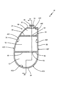
[0027] FIG. 3A is a side cross-sectional view of a first embodiment of
conformable tank
18 taken along line A-A of FIG. 2. FIG. 3B is a side cross-section view of the
first embodiment
of conformable tank 18 taken along line 3B-3B of FIG. 3A. Conformable tank 18
includes body
24 and port 26. Body 24 includes front wall 28, rear wall 30, top wall 32,
bottom wall 34, curved
side wall 36, and flat side wall 38. Front wall 28, rear wall 30, top wall 32,
bottom wall 34,
curved side wall 36, and flat side wall 38 include inner surfaces 40A, 40B,
40C, 40D, 40E, and
40F, and outer surfaces 42A, 42B, 42C, 42D, 42E, and 42F, respectively.
Conformable tank 18
further includes first baffle 44, second baffle 46, first cavity 48, second
cavity 50, third cavity 52,
first aperture 54, second aperture 56, and third aperture 58.
[0028] Conformable tank 18 includes body 24 that forms a housing of
conformable tank
18. Port 26 extends through body 24 of conformable tank 18 to provide an
inlet/outlet to
conformable tank 18. Body 24 of conformable tank 18 includes front wall 28
that is positioned
opposite of rear wall 30, top wall 32 that is positioned opposite of bottom
wall 34, and curved
side wall 36 that is positioned opposite of flat side wall 38.
[0029] Front wall 28 includes inner surface 40A and outer surface 42A.
Rear wall 30
includes inner surface 40B and outer surface 42B. Top wall 32 includes inner
surface 40C and
outer surface 42C. Bottom wall 34 includes inner surface 40D and outer surface
42D. Curved
side wall 36 includes inner surface 40E and outer surface 42E. Flat side wall
38 includes inner
surface 40F and outer surface 42F. Inner surfaces 40A, 40B, 40C, 40D, 40E, and
40F form an
interior of conformable tank 18 and outer surfaces 42A, 42B, 42C, 42D, 42E,
and 42F form an
exterior of conformable tank 18.
[0030] Conformable tank 18 further includes first baffle 44 and second
baffle 46
extending through an interior of conformable tank 18. First baffle 44 extends
from inner surface
CA 3015647 2018-08-27
40E of curved side wall 36 to inner surface 40F of flat side wall 38. First
baffle 44 also extends
from inner surface 40A of front wall 28 to inner surface 40B of rear wall 30.
Second baffle 46
extends from inner surface 40E of curved side wall 36 to inner surface 40F of
flat side wall 38.
Second baffle 46 also extends from inner surface 40A of front wall 28 to inner
surface 40B of
rear wall 30.
[0031] First baffle 44 and second baffle 46 are configured to act as
internal supports and
provide structural support to body 24 of conformable tank 18. Without first
baffle 44 and second
baffle 46, conformable tank 18 could deform under internal pressure. In the
embodiment shown,
conformable tank 18 includes two baffles. In alternate embodiments,
conformable tank 18 can
include any number of baffles.
[0032] First baffle 44 and second baffle 46 divide the interior of
conformable tank 18
into first cavity 48, second cavity 50, and third cavity 52. First cavity 48
is defined as the volume
enclosed by front wall 28, rear wall 30, top wall 32, curved side wall 36,
flat side wall 38, and
first baffle 44. Second cavity 50 is defined as the volume enclosed by front
wall 28, rear wall 30,
curved side wall 36, flat side wall 38, first baffle 44, and second baffle 46.
Third cavity 52 is
defined as the volume enclosed by front wall 28, rear wall 30, bottom wall 34,
curved side wall
36, and flat side wall 38, and second baffle 46. First cavity 48, second
cavity 50, and third cavity
52 are configured to store potable water, or any other fluid, at an elevated
pressure in
conformable tank 18.
[0033] Extending through first baffle 44 and fluidly connecting first
cavity 48 and second
cavity 50 is first aperture 54. Extending through second baffle 46 and fluidly
connecting second
cavity 50 and third cavity 52 is second aperture 56. The embodiment shown in
FIGS. 3A-3B
shows a single aperture extending through each baffle. Alternate embodiments
may include any
number of apertures extending through each baffle. Further, the apertures can
be of equal shape
and size or varying shape and size.
[0034] Extending through top wall 32 is third aperture 58. Third aperture
58 provides a
means for filling and emptying conformable tank 18. Third aperture 58 can be
fitted with port 26
or any other component used to aid in filling and emptying conformable tank
18. According to
the embodiment shown in FIGS. 3A-3B, third aperture 58 extends through top
wall 32. In
alternate embodiments, third aperture 58 can extend through any of the walls
of body 24, such as
front wall 28, rear wall 30, top wall 32, bottom wall 34, curved side wall 36,
or flat side wall 38.
6
CA 3015647 2018-08-27
[0035] Conformable tank 18 is configured to store fluids, particularly
potable water, at an
elevated pressure when compared to ambient pressure outside conformable tank
18. The baffles
within conformable tank 18 provide structural support to prevent excessive
deformation from the
internal pressure while still allowing fluid to pass from cavity to cavity.
Conformable tank 18 can
be designed to fit in and conform to a plurality of irregular aircraft spaces.
[0036] FIG. 4A is a side cross-sectional view of a second embodiment of
conformable
tank 18 taken along line A-A of FIG. 2. FIG. 4B is a side cross-sectional view
of the second
embodiment of conformable tank 18 taken along line 4B-4B of FIG. 4A.
Conformable tank 18
includes body 24 and port 26. Body 24 includes front wall 28, rear wall 30,
top wall 32, bottom
wall 34, curved side wall 36, and flat side wall 38. Front wall 28, rear wall
30, top wall 32,
bottom wall 34, curved side wall 36, and flat side wall 38 include inner
surfaces 40A, 40B, 40C,
40D, 40E, and 40F, and outer surfaces 42A, 42B, 42C, 42D, 42E, and 42F,
respectively.
Conformable tank 18 further includes internal cavity 60, first rib 62, second
rib 64, third rib 66,
and fourth rib 68.
[0037] Conformable tank 18 includes body 24 that forms a housing of
conformable tank
18. Port 26 extends through body 24 of conformable tank 18 to provide an
inlet/outlet to
conformable tank 18. Body 24 of conformable tank 18 includes front wall 28
that is positioned
opposite of rear wall 30, top wall 32 that is positioned opposite of bottom
wall 34, and curved
side wall 36 that is positioned opposite of flat side wall 38.
[0038] Front wall 28 includes inner surface 40A and outer surface 42A.
Rear wall 30
includes inner surface 40B and outer surface 42B. Top wall 32 includes inner
surface 40C and
outer surface 42C. Bottom wall 34 includes inner surface 40D and outer surface
42D. Curved
side wall 36 includes inner surface 40E and outer surface 42E. Flat side wall
38 includes inner
surface 40F and outer surface 42F. Inner surfaces 40A, 40B, 40C, 40D, 40E, and
40F form an
interior of conformable tank 18 and outer surfaces 42A, 42B, 42C, 42D, 42E,
and 42F form an
exterior of conformable tank 18. Internal cavity 60 is formed in the interior
of conformable tank
18.
[0039] Conformable tank 18 includes first rib 62, second rib 64, third
rib 66, and fourth
rib 68 in cavity 60 to provide structural support for conformable tank 18.
First rib 62 extends
along inner surface 40B of rear wall 30 and abuts inner surface 40F of flat
side wall 38 and
protrudes into internal cavity 60. Second rib 64 extends along inner surface
40F of flat side wall
7
CA 3015647 2018-08-27
38 and protrudes into internal cavity 60. Third rib 66 extends along inner
surface 40B of rear
wall 30 and protrudes into internal cavity 60. Fourth rib 68 extends from
inner surface 40D of
bottom wall 34 and protrudes into internal cavity 60.
[0040] The embodiment shown in FIGS. 4A-4B is on embodiment of
conformable tank
18 with ribs utilized as internal supports. The ribs provide structural
support to conformable tank
18 and prevent it from deforming excessively under internal pressure. This
embodiment is not
meant to limit the disclosure to a single embodiment. In alternate
embodiments, conformable
tank 18 can include a plurality of ribs of varying shapes and sizes. The ribs
can connect to any of
the walls of body 24 and extend along or protrude from the walls in any
suitable manner.
[0041] Conformable tank 18 is configured to store fluids, particularly
potable water, at an
elevated pressure when compared to ambient pressure outside conformable tank
18. The ribs
within conformable tank 18 provide structural support to prevent excessive
deformation from the
internal pressure while still allowing fluid flow within the internal cavity.
Conformable tank 18
can be designed to fit in and conform to a plurality of irregular aircraft
spaces.
[0042] FIG. 5 is a cross-sectional view of tank wall 100 including
sandwich structure
102. Sandwich structure 102 includes interior facing 104, exterior facing 106,
and core 108.
Interior facing 104 includes inner surface 110, and exterior facing 106
includes outer surface
112.
[0043] Tank wall 100 can be any of front wall 28, rear wall 30, top wall
32, bottom wall
34, curved side wall 36, and flat side wall 38, as discussed in reference to
FIGS. 2-4B. Tank
wall 100 includes sandwich structure 102. Sandwich structure 102 is
constructed with interior
facing 104 separated from exterior facing 106 by core 108. Interior facing 104
and exterior
facing 106 are a composite material such as thermoplastic, fiberglass, carbon
fiber reinforced
plastic, synthetic fibers (such as Kevlar or aramid fibers), or any
combination thereof. Core 108 is
displaced between and physically contacts interior facing 104 and exterior
facing 106. Core 108
may be made of composite honeycomb, foam, like material or any combination
thereof. When
core 108 includes composite honeycomb, the composite honeycomb may be made of
thermoplastic, fiberglass, carbon materials, synthetic fibers (such as Kevlar0
or aramid fibers), like
material, or any combination thereof. The cell size, density, and shape of the
honeycomb or foam
of core 108 can also vary in order to meet tank design specifications.
Interior facing 104 forms
inner surface 110 of tank wall 100, inner surface 110 being positioned to face
an interior of
8
CA 3015647 2018-08-27
conformable tank 18. Exterior facing 106 forms outer surface 112 of tank wall
100, outer surface
112 being positioned to face an exterior of conformable tank 18. Interior
surface 110 and exterior
surface 112 may be covered with non-structural materials to prevent water
leakage, as a chemical
barrier, for aesthetics, for thermal insulation, or for electrical
conductivity.
[0044] Core 108 is made of lightweight material that supports interior
facing 104 and
exterior facing 106. Sandwich structure 102 increases relative stiffness and
strength of tank wall
100 without substantially increasing the weight of tank wall 100. This results
in conformable
tank 18 (shown in FIGS. 1A-4B) that is lightweight relative to a similarly
constructed metal tank
while still being able to meet the rigorous pressure (e.g. operating pressure,
proof pressure, burst
pressure), mounting, vibration, flight load, and shock specifications required
for an application
such as aircraft use. The sandwich structure 102 wall is particularly useful
for conformable tank
18 with flat walls and sharp corners where internal pressures can cause large
bending stresses.
[0045] FIG. 6A is a cross-sectional view of tank wall 100 with internal
support 114
integrally connected to exterior facing 106 of sandwich structure 102. FIG. 6B
is a cross-
sectional view of tank wall 100 with internal support 114 integrally connected
to interior facing
104 of sandwich structure 102. FIG. 6C is a cross-sectional view of tank wall
100 with internal
support 114 integrally connected to sandwich structure 102 by mechanical
fastener 116. Tank
wall 100 includes sandwich structure 102. Sandwich structure 102 includes
interior facing 104,
exterior facing 106, and core 108. Interior facing 104 includes inner surface
110, and exterior
facing 106 includes outer surface 112. FIGS. 6A-6B further show internal
support 114. FIG. 6C
also shows mechanical fastener 116. Mechanical fastener 116 includes head 118.
[0046] Referring to FIGS. 6A-6C, tank wall 100 is made of sandwich
structure 102.
Sandwich structure 102 is constructed with interior facing 104 separated from
exterior facing
106 by core 108. Interior facing 104 forms inner surface 110 of tank wall 100,
inner surface 110
being positioned in an interior of conformable tank 18. Exterior facing 106
forms outer surface
112 of tank wall 100, outer surface 112 being positioned in an exterior of
conformable tank 18.
Internal support 114 is attached to tank wall 100. Internal support 114 may be
a rib (as shown in
FIGS. 4A-4B) or a baffle (as shown in FIGS. 3A-3B) consisting of any composite
material such
as thermoplastic, fiberglass, carbon fiber reinforced plastic, synthetic
fibers (such as Kevlar0 or
aramid fibers), or any combination thereof.
9
CA 3015647 2018-08-27
[0047] Referring now to FIG. 6A, internal support 114 is attached to tank
wall 100 by
being integrally connected to exterior facing 106 and extending through
interior facing 104 and
core 108. One way of integrally connecting internal support 114 to exterior
facing 106 is by
weaving internal support 114 into exterior facing 106. Weaving, as used
herein, means braiding,
stitching, sewing, contour weaving, steered weaving, and through thickness
weaving.
[0048] Referring now to FIG. 6B, internal support 114 may be attached to
wall 100 by
being integrally connected to interior facing 104. Integrally connecting
internal support 114 to
interior facing 104 may be accomplished by weaving internal support 114 into
interior facing
104.
[0049] In another embodiment shown in FIG. 6C, internal support 114 is
attached to tank
wall 100 by mechanical fastener 116. Mechanical fastener 116 extends through
exterior facing
106, core 108, and interior facing 104. Mechanical fastener 116 is attached to
internal support
114 and holds internal support 114 in place. Mechanical fastener 116 may be
attached to internal
support 114 by an embedded nut disposed in internal support 114. Where an
embedded nut is
used, mechanical fastener 116 is threaded into the embedded nut to connect
mechanical fastener
116 to internal support 114. Mechanical fastener 116 includes head 118, which
is larger than the
hole extending through tank wall 100 in which mechanical fastener 116 is
placed. Thus,
mechanical fastener 116 can be secured in place by tank wall 100 and attached
to internal
support 114.
[0050] Internal supports 114 provide support to tank wall 100 and prevent
excessive
bending of the flat walls due to internal or external forces. FIGS. 6A-6C
represent three ways of
attaching internal supports 114 to tank wall 100 comprising sandwich structure
102.
[0051] FIG. 7A is a cross-sectional view of a first embodiment of
conformable tank 18
having sandwich structure 102. Figure 7B is a cross-sectional view of a second
embodiment of
conformable tank 18 having sandwich structure 102. Conformable tank 18
includes body 24.
Body 24 includes front wall 28 (shown in FIG. 2), rear wall 30, top wall 32,
bottom wall 34,
curved side wall 36, and flat side wall 38. Conformable tank 18 further
includes first baffle 44,
second baffle 46, first cavity 48, second cavity 50, third cavity 52, sandwich
structure 102, single
facing composite structure 120, and corners 122.
[0052] As shown in FIGS. 7A-7B, conformable tank 18 includes body 24.
Body 24 of
conformable tank 18 includes front wall 28 that is positioned opposite of rear
wall 30, top wall
CA 3015647 2018-08-27
32 that is positioned opposite of bottom wall 34, and curved side wall 36 that
is positioned
opposite of flat side wall 38. Conformable tank 18 further includes first
baffle 44 and second
baffle 46 extending through an interior of conformable tank 18. First baffle
44 extends from
curved side wall 36 to flat side wall 38 and from front wall 28 to rear wall
30. Second baffle 46
extends from inner surface 40E of curved side wall 36 to inner surface 40F of
flat side wall 38.
Second baffle 46 also extends from inner surface 40A of front wall 28 to inner
surface 40B of
rear wall 30.
[0053] Conformable tank 18 has areas with sandwich structure 102 and
areas with single
facing composite structure 120. Single facing composite structure 120
comprises one facing
which may be thermoplastic, fiberglass, carbon fiber reinforced plastic,
Kevlar, aramid, or any
combination thereof. Single composite facing structure 120 is thinner and
lighter than sandwich
structure 102, Conformable tank 18 also includes corners 122. Corners 122 can
include any
corners where any of front wall 28, rear wall 30, top wall 32, bottom wall 34,
curved side wall
36, and flat side wall 38 meet one another. Sandwich structure 102 can be
positioned in corners
122. It is possible that corners 122 include minimal or no core 108 (shown in
FIG. 5) of
sandwich structure 102. This reduces the local flexural rigidity of corners
122 and reduces the
local compressive stress on interior facing 104 and exterior facing 106.
[0054] In FIG. 7A, front wall 28 (not shown in FIG. 7A), rear wall 30,
top wall 32,
curved side wall 36, and flat side wall 38 are made out of sandwich structure
102. Bottom wall
34 is made out of single facing composite structure 120. Bottom wall 34 is
rounded and is an
area where compressive stresses are low enough that added support from
sandwich structure 102
is not required to meet design specifications of conformable tank 18. Bottom
wall 34 incurs
lower bending stresses relative to the curved side wall 36 and flat side wall
38 of conformable
tank 18. Thus, single facing composite structure 120 may be used to reduce the
overall weight of
conformable tank 18 while still meeting required operating, proof, and burst
pressures of
conformable tank 18.
[0055] In FIG. 7B, front wall 28 (not shown in FIG. 7A), rear wall 30,
top wall 32,
bottom wall 34, curved side wall 36, and flat side wall 38 all mostly made out
of sandwich
structure 102. In the areas where first baffle 44 and second baffle 46 connect
to front wall 28,
rear wall 30, curved side wall 36, and flat side wall 38, conformable tank 18
is made out of
single facing composite structure 120. Front wall 28, rear wall 30, curved
side wall 36, and flat
11
CA 3015647 2018-08-27
side wall 38 include sandwich structure 102 positioned betw -en the areas
where first baffle 44
and second baffle 46 connect to front wall 28, rear wall 30, curved side wall
36, and flat side
wall 38.
[0056] As seen in FIGS. 7A-78, conformable tank 18 can have sandwich
structure 102
located in first sections and single facing composite structure 120 located in
second sections.
FIGS. 7A-78 are two embodiments of conformable tank 18, however in alternate
embodiments
conformable tank 18 can have first sections with sandwich structure 102 and
second sections
with single facing composite structure 120 located in any areas of conformable
tank 18.
[0057] It is advantageous to reduce the amount of sandwich structure 102
used in
conformable tank 18, because sandwich structure 102 is heavier and thicker
than single
composite facing structure 120. Sandwich structure 102 is used for added
strength and stiffness.
Single facing composite structure 120 is used where increased strength and
stiffness is less
desirable relative to flat areas of conformable tank 18. Thus, the overall
weight of conformable
tank 18 may be reduced by utilizing single facing composite structure 120
while still meeting
required operating, proof, and burst pressures of conformable onk 18.
[0058] Discussion of Possible Embodiments
[0059] The following are non-exclusive descriptions of possible
embodiments of the
present invention.
[0060] A conformable tank includes a body with a plurality of composite
walls formed
around a cavity, and an internal support connected to one of the plurality of
composite walls and
positioned in the cavity. The plurality of composite walls includes a flat
side wall disposed
opposite a curved side wall. A first section of one of the plurality of
composite walls includes an
exterior facing, an interior facing, and a core positioned between the
exterior facing and the
interior facing.
[0061] The conformable tank of the preceding paragraph can optionally
include,
additionally and/or alternatively, any one or more of the following features,
configurations
and/or additional components:
[0062] Wherein the plurality of composite walls includes a top wall
connected to the
curved side wall and the flat side wall; a bottom wall connected to the curved
side wall and the
flat side wall; a front wall connected to the curved side wall, the top wall,
the flat side wall, and
12
CA 3015647 2018-08-27
the bottom wall; and a rear wall connected to the curved side wall, the top
wall, the flat side wall,
and the bottom wall.
[0063] Wherein the first section of one of the plurality of composite
walls is a first
section of the flat side wall.
[0064] Wherein a second section of the flat side wall includes a single
facing composite
structure.
[0065] Wherein the bottom wall comprises a single facing composite
structure.
[0066] Wherein the internal support is a baffle.
[0067] Wherein the baffle extends through the interior facing and the
core of the first
section of one of the plurality of composite walls and is integrally formed
with the exterior
facing.
[0068] Wherein the baffle is connected to the first section of one of the
plurality of
composite walls by a mechanical fastener that extends through the exterior
facing, the core, and
the interior facing of the first section of one of the plurality of composite
walls.
[0069] Wherein the internal support is a rib.
[0070] Wherein the rib extends through the interior facing and the core
of the first section
of one of the plurality of composite walls and is integrally formed with the
exterior facing.
[0071] Wherein the rib is connected to the first section of one of the
plurality of
composite walls by a mechanical fastener that extends through the exterior
facing, the core, and
the interior facing of the first section of one of the plurality of composite
walls.
[0072] Wherein the core is selected from the group consisting of
honeycomb, foam, or
any combination thereof.
[0073] A potable water system for an aircraft includes a conformable tank
positioned
adjacent to a fuselage of the aircraft that is configured to hold potable
water, a fluid flow inducer
connected to the conformable tank that is configured to pump water through the
potable water
system, and a control valve connected to the fluid flow inducer and the
conformable tank that is
configured to control the flow of water. The conformable tank includes a body
with a plurality
of composite walls formed around a cavity, and an internal support connected
to one of the
plurality of composite walls and positioned in the cavity. A fist section of
one of the plurality of
composite walls includes an exterior facing, an interior facing, and a core
positioned between the
exterior facing and the interior facing.
13
CA 3015647 2018-08-27
[0074] The potable water system of the preceding paragraph can optionally
include,
additionally and/or alternatively, any one or more of the following features,
configurations
and/or additional components:
[0075] Wherein the body of the conformable tank includes a second section
of one of the
plurality of composite walls includes a single facing composite structure.
[0076] Wherein the second section of one of the plurality of composite
walls is
connected to the internal support.
[0077] Wherein the internal support extends through the interior facing
and the core of
the first section of one of the plurality of composite walls and is integrally
formed with the
exterior facing.
[0078] Wherein the internal support is connected to the first section of
one of the
plurality of composite walls by a mechanical fastener that extends through the
exterior facing,
the core, and the interior facing of the first section of one of the plurality
of composite walls.
[0079] Wherein the core is selected from the group consisting of
honeycomb, foam, or
any combination thereof.
[0080] Wherein the internal support is a baffle or a rib.
[0081] Wherein the fluid flow inducer is a hydraulic pump or a compressed
air system.
[0082] While the invention has been described with reference to an
exemplary
embodiment(s), it will be understood by those skilled in the art that various
changes may be
made and equivalents may be substituted for elements thereof without departing
from the scope
of the invention. In addition, many modifications may be made to adapt a
particular situation or
material to the teachings of the invention without departing from the
essential scope thereof.
Therefore, it is intended that the invention not be limited to the particular
embodiment(s)
disclosed, but that the invention will include all embodiments falling within
the scope of the
appended claims.
14
CA 3015647 2018-08-27