Note: Descriptions are shown in the official language in which they were submitted.
ULTRASONIC FLUID MEASUREMENT PROBE
WITH ULTRASONICALLY WELDED BASE CAP
BACKGROUND INFORMATION
1. Field:
The present disclosure relates generally to systems and methods for ultrasonic
fluid measurement. More particularly, the present disclosure relates to an
ultrasonic
fluid measurement probe for measuring the level of fluid in a container, such
as for
measuring the level of fuel in a fuel tank on an aircraft or other vehicle.
2. Background:
Ultrasonic sensing uses ultrasonic transducers to transmit ultrasonic waves
and to receive those ultrasonic waves reflected by an object. The time delay
between transmission and reception of the ultrasonic waves may be used to
determine the distance of the object from an ultrasonic transducer. Ultrasonic
transducers may be used to determine the height or level of fluid in a
container by
reflecting an ultrasonic signal from the surface of the fluid in the
container. For
example, without limitation, ultrasonic sensing may be used for fuel gauging,
to
measure the level of fuel in a fuel tank on an aircraft or other vehicle.
A current fuel probe assembly is comprised of a piezoelectric transducer that
is
glued to a plastic base inside a cavity. The transducer has wires soldered to
it. A
foam pad is placed on top of the transducer to create an air space. The foam
pad is
covered by a polysulfide potting material to seal out fuel from the air space
created
by the foam pad.
There may be a need for a method and apparatus that take into account at
least some limitations of current fuel probes, as well as other possible
issues.
1
CA 3016214 2018-08-30
SUMMARY
In one embodiment there is provided an apparatus comprising a base
comprising a transducer chamber, wherein the transducer chamber comprises a
transducer chamber floor, a transducer chamber edge, and transducer chamber
walls extending from the transducer chamber floor to the transducer chamber
edge.
The apparatus further includes an ultrasonic transducer attached to the
transducer
chamber floor and a tube comprising an end attached to the base such that an
ultrasonic signal generated by the ultrasonic transducer is directed into the
tube.
The apparatus further includes a fluid entry port formed in the tube where the
tube is
attached to the base and a cap welded to the transducer chamber edge and that,
along with the transducer chamber floor and the transducer chamber walls,
encloses
the transducer chamber to form an enclosed air space between the ultrasonic
transducer and the cap.
The base may further include a flange portion, and a mounting hole in the
flange portion.
The base may also include a wiring channel in communication with the
transducer chamber, wherein the wiring channel comprises a wiring channel
floor, a
wiring channel edge, and wiring channel walls extending from the wiring
channel
floor to the wiring channel edge and wherein the cap is welded to the wiring
channel
edge.
The apparatus may also include wires attached to the ultrasonic transducer
and extending from the ultrasonic transducer, through the transducer chamber,
through the wiring channel, and through the wiring channel floor.
The wires may be soldered to the ultrasonic transducer.
The ultrasonic transducer may be a piezoelectric transducer.
The cap may be made of plastic. This may enhance the design as a result of a
decrease in weight while not impacting performance or reliability.
2
Date recue / Date received 2021-12-13
The cap may be fabricated from polyphenylene sulphide. The base may be
attached to an inside surface of a fuel tank on an aircraft such that the tube
extends
from the base into the fuel tank.
In another embodiment there is provided a method of enhancing reliability of
an
ultrasonic fluid measurement probe. The method involves generating an
ultrasonic
signal by an ultrasonic transducer in a transducer chamber in a base of the
ultrasonic fluid measurement probe such that the ultrasonic signal is directed
into a
tube comprising an end attached to the base of the ultrasonic fluid
measurement
probe. The transducer chamber comprises a transducer chamber floor, transducer
chamber walls, and a cap welded to an edge of the transducer chamber walls
such
that the cap, along with the transducer chamber floor and the transducer
chamber
walls, encloses the transducer chamber to form an enclosed air space. The
method
further involves detecting a reflection of the ultrasonic signal by the
ultrasonic
transducer.
The method may also include processing the detected reflection of the
ultrasonic signal to determine a level of fluid in a container. This can
enhance
performance and reliability.
Processing the detected reflection of the ultrasonic signal to determine the
level
of fluid in a container may include processing the detected reflection of the
ultrasonic
signal to determine a level of fuel in a fuel tank.
The base may further comprise a wiring channel in communication with the
transducer chamber and the wiring channel have a wiring channel floor, a
wiring
channel edge, and wiring channel walls extending from the wiring channel floor
to
the wiring channel edge. The cap may be welded to the wiring channel edge.
In another embodiment there is provided a method of enhancing reliability of
an
ultrasonic fluid measurement probe. The method involves attaching an
ultrasonic
transducer to a transducer chamber floor of a transducer chamber in a base,
wherein the transducer chamber comprises the transducer chamber floor, a
transducer chamber edge, and transducer chamber walls extending from the
3
Date recue / Date received 2021-12-13
transducer chamber floor to the transducer chamber edge. The method further
involves welding a cap to the transducer chamber edge such that the cap, along
with
the transducer chamber floor and the transducer chamber walls, encloses the
transducer chamber to form an enclosed air space between the ultrasonic
transducer and the cap. The method further involves attaching an end of a tube
to
the base such that an ultrasonic signal generated by the ultrasonic transducer
is
directed into the tube.
The base may also include a wiring channel in communication with the
transducer chamber, wherein the wiring channel may also include a wiring
channel
floor, a wiring channel edge, and wiring channel walls extending from the
wiring
channel floor to the wiring channel edge, and the method may further include
welding the cap to the wiring channel edge.
The method may also include attaching wires to the ultrasonic transducer; and
extending the wires from the ultrasonic transducer, through the transducer
chamber,
.. through the wiring channel, and through the wiring channel floor.
The cap may be made of plastic.
The cap may be made of polyphenylene sulphide.
Welding the cap to the transducer chamber edge may include ultrasonically
welding the cap to the transducer chamber edge.
The method may also include detecting a reflection of the ultrasonic signal by
the ultrasonic transducer and processing the detected reflection of the
ultrasonic
signal to determine a level of fluid in a container.
In another embodiment, there is provided an ultrasonic fluid measurement
probe comprising a base comprising a transducer chamber having a transducer
chamber floor, a transducer chamber edge, and transducer chamber walls
extending
from the transducer chamber floor to the transducer chamber edge. The probe
further includes an ultrasonic transducer attached to the transducer chamber
floor,
and a cap ultrasonically welded to the transducer chamber edge and that, along
with
4
Date recue / Date received 2021-12-13
the transducer chamber floor and the transducer chamber walls, encloses the
transducer chamber to form an enclosed air space between the ultrasonic
transducer and the cap. The probe further includes a tube attached to the base
such
that an ultrasonic signal generated by the ultrasonic transducer is directed
into the
tube.
In another embodiment, there is provided a method of enhancing reliability of
an ultrasonic fluid measurement probe. The method involves attaching an
ultrasonic
transducer to a transducer chamber floor of a transducer chamber in a base,
wherein the transducer chamber comprises the transducer chamber floor, a
transducer chamber edge, and transducer chamber walls extending from the
transducer chamber floor to the transducer chamber edge. The method further
involves ultrasonically welding a cap to the transducer chamber edge such that
the
cap, along with the transducer chamber floor and the transducer chamber walls,
encloses the transducer chamber to form an enclosed air space between the
ultrasonic transducer and the cap. The method further includes attaching a
tube to
the base such that an ultrasonic signal generated by the ultrasonic transducer
is
directed into the tube.
The features and functions can be achieved independently in various
embodiments of the present disclosure or may be combined in yet other
embodiments in which further details can be seen with reference to the
following
description and drawings.
BRIEF DESCRIPTION OF THE DRAWINGS
Illustrative embodiments, as well as a preferred mode of use, further
objectives,
and features thereof, will best be understood by reference to the following
detailed
description of an illustrative embodiment of the present disclosure when read
in
conjunction with the accompanying drawings, wherein:
Figure 1 is an illustration of a block diagram of an ultrasonic fuel gauging
system in accordance with an illustrative embodiment;
5
Date recue / Date received 2021-12-13
Figure 2 is an illustration of a block diagram of an ultrasonic fluid
measurement
probe with an ultrasonically welded base cap in accordance with an
illustrative
embodiment;
Figure 3 is an illustration of an exploded perspective view of a base assembly
for an ultrasonic fluid measurement probe in accordance with an illustrative
embodiment;
Figure 4 is an illustration of a perspective view of the base assembly for an
ultrasonic fluid measurement probe of Figure 3 with a cap ultrasonically
welded to a
base in accordance with an illustrative embodiment; and
Figure 5 is an illustration of a flow chart of a method of making and using an
ultrasonic fluid measurement probe in accordance with an illustrative
embodiment.
5a
Date recue / Date received 2021-12-13
DETAILED DESCRIPTION
The illustrative embodiments recognize and take into account different
considerations. For example, the illustrative embodiments recognize and take
into
account that ultrasonic fuel measuring probes in fuel tanks on aircraft may be
subject
to extreme environmental conditions which may cause them to need to be
repaired
or replaced prematurely. An aircraft may need to be removed from service and
maintenance personnel may need to perform a fuel tank entry when an ultrasonic
fuel probe in an aircraft fuel tank needs to be repaired or replaced. Fuel
tank entry
by maintenance personnel to repair or replace a fuel probe requires draining
and
.. purging of the fuel tank. In many cases, repair or replacement of an
ultrasonic fuel
probe in the fuel tank of an aircraft may require up to two days of down time
in which
the aircraft is out of service. Such down time may be very costly to an
airline or
other operator of the aircraft.
There may be relatively very many ultrasonic fuel measurement probes on an
aircraft. For example, a Boeing 777-300ER passenger aircraft may use 76
ultrasonic fuel measurement probes in a fuel quantity indicating system.
Illustrative
embodiments recognize and take into account that reliability for commercial
passenger aircraft and other aircraft may be improved and the cost of
operating such
aircraft reduced by reducing the need to repair or replace the ultrasonic fuel
measurement probes that may be used for fuel gauging in such aircraft.
Illustrative embodiments recognize and take into account that the polysulfide
potting around the transducer in the base of a conventional ultrasonic fuel
measurement probe may not perform as desired and thereby may allow fuel
ingress
into the foam pad area of the transducer. Fuel in the foam pad compromises the
air
space around the transducer and may result in the transducer being sensitive
to
reflections from the opposite direction it was intended to. This sensitivity
to
reflections from the opposite direction than intended may result in a reading
from the
ultrasonic transducer of a fuel height corresponding to the distance between
the
ultrasonic transducer and the bottom of the fuel tank on which the ultrasonic
fuel
6
CA 3016214 2018-08-30
measurement probe is placed. For example, a conventional ultrasonic
fuel
measurement probe in which an inconsistency in the polysulfide potting
material
results in fuel in the foam pad area around the ultrasonic transducer may
provide a
reading that indicates a fuel height of one or two centimeters regardless of
the actual
height of fuel in the fuel tank.
Illustrative embodiments recognize and take into account that the polysulfide
potting material in the base of an ultrasonic fuel measurement probe that is
used to
measure fuel height in an aircraft fuel tank may flex as the aircraft changes
altitude
from ground level to cruise altitude. Air trapped in the air space between the
polysulfide potting material and the ultrasonic transducer remains at ground
level
pressure, therefore, the polysulfide potting material must endure a pressure
difference between the pressure at ground level and the pressure at cruise
level.
For example, without limitation, the polysulfide potting material may be
required to
endure a pressure difference between sea level pressure in the air space on
one
side of the polysulfide potting material and the pressure at a cruising
altitude near
40,000 feet above sea level on the other side of the polysulfide potting
material.
Such a pressure differential may cause the polysulfide potting material to
expand
under internal pressure from the air in the air space as the aircraft climbs
from the
ground to cruising altitude and then contract again as the aircraft descends
from
cruising altitude to the ground for landing. This cyclic mechanical stress may
eventually compromise the seal of the polysulfide potting material. This
cyclic
mechanical stress also may cause tension in the wires that are soldered to the
ultrasonic transducer disk, which may cause inconsistencies in the solder
joints.
Illustrative embodiments also recognize and take into account that various
manufacturing issues may be associated with the use of polysulfide potting
material
in the base of an ultrasonic fluid measurement probe. For example, without
limitation, contamination of the polysulfide potting material, achieving the
appropriate
ratio of materials that may be mixed together to form the polysulfide potting
material,
and achieving an acceptable consistency in the thickness of the polysulfide
potting
material deposited on the base of the probe may be some of the issues
associated
7
CA 3016214 2018-08-30
with the use of a polysulfide potting material in the base of a known
ultrasonic fluid
measurement probe.
Illustrative embodiments recognize and take into account that sealing the
transducer chamber in the base of an ultrasonic fluid measurement probe with a
polysulfide potting material may be relatively messy and difficult to
accomplish. For
example, without limitation, the surfaces of the base that are to be adjacent
to the
polysulfide potting material may have to be bead blasted and cleaned
thoroughly to
allow the polysulfide potting material to adhere completely. The polysulfide
material
used for the potting in an ultrasonic fluid measurement probe for fuel gauging
may
be made from a two part compound that may require mixing in precise ratios for
curing and that must be contamination free.
Furthermore, deposition of the
polysulfide potting material on the base of an ultrasonic fluid measurement
probe to
seal the transducer chamber may require expert skilled labor.
Illustrative embodiments eliminate the foam pad and polysulfide potting
material used in the base of a conventional ultrasonic fuel probe. In
accordance with
an illustrative embodiment, the cavity containing the ultrasonic transducer is
sealed
with a plastic cap that is ultrasonically welded to the base. The foam pad and
polysulfide potting material used in conventional ultrasonic fuel probes are
not
required.
Ultrasonic welding of a cap to seal the air space around the ultrasonic
transducer of an ultrasonic fluid measurement probe may reduce or eliminate
the
various limitations of using polysulfide potting material in the base of an
ultrasonic
fluid measurement probe for such purpose. The strength and durability of the
ultrasonically welded cap would not only eliminate the manufacturing issues
associated with using a polysulfide potting material, but would also provide a
significantly more robust design against environmental stresses. The result is
a part
that is more easily manufactured and more durable. An ultrasonic fuel
measurement
probe in accordance with an illustrative embodiment would not need to be
repaired
8
CA 3016214 2018-08-30
or replaced as often as a conventional ultrasonic fluid measurement probe
using
polysulfide potting material.
Turning to Figure 1, an illustration of a block diagram of an ultrasonic fuel
gauging system is depicted in accordance with an illustrative embodiment. For
example, without limitation, ultrasonic fuel gauging system 100 may comprise
part of
a fuel quantity indicating system for indicating the amount of fuel in fuel
tanks 102 on
an aircraft.
Ultrasonic fuel gauging system 100 may be configured to perform a variety of
functions. For example, without limitation, ultrasonic fuel gauging system 100
may
be configured to measure fuel quantity in fuel tanks 102, calculate the weight
of fuel
in fuel tanks 102, measure the temperature of the fuel in fuel tanks 102,
control
fueling operations, and show when there is water in fuel tanks 102.
Components of fuel gauging system 100 may include ultrasonic sensor probes
104 for measuring fuel height, densitometers 106, temperature sensors 108, and
water detectors 110. Each ultrasonic sensor probe 104 may comprise base 122
and
tube 124. Base 122 of each ultrasonic sensor probe 104 may comprise an
ultrasonic transducer. Densitometers 106 measure the fuel density in each fuel
tank
102.
Appropriate wiring may be used to connect the ultrasonic fuel sensor probes
104 to fuel quantity processor unit 112. Fuel quantity processor unit 112 may
send a
signal to each ultrasonic sensor probe 104 to find the fuel height. The
ultrasonic
sensor probe 104 sends a sound pulse from base 122 at the bottom of fuel tank
102
to the fuel surface in tube 124 attached to base 122. Fuel quantity processor
unit
112 calculates the fuel height by measuring the time it takes for the pulse to
give a
reflection back to base 118.
Fuel quantity processor unit 112 may use the fuel height to calculate the fuel
volume. Fuel quantity processor unit 112 may then multiply fuel volume and
density
to calculate the fuel weight. Fuel quantity processor unit 112 may send fuel
quantity
9
CA 3016214 2018-08-30
data to integrated refuel panel 114 and to display 116 on the flight deck of
the
aircraft.
The speed of the ultrasonic signal sent through the fuel in ultrasonic sensor
probe 104 is dependent on fuel density and temperature. Densitometer 106 in
each
fuel tank 102 may be used to calculate fuel type during refueling. Some of
ultrasonic
sensor probes 104 may be calibration probes configured to calibrate the
calculations
of fuel height based on the information provided by other ultrasonic sensor
probes
104 in fuel tanks 102.
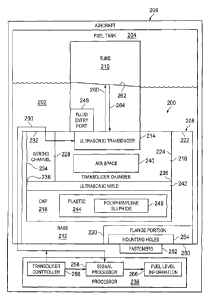
Turning to Figure 2, an illustration of a block diagram of an ultrasonic fluid
measurement probe with an ultrasonically welded base cap is depicted in
accordance with an illustrative embodiment. Probe 200 may be an ultrasonic
fluid
measurement probe that is used to determine the quantity of fuel 202 in fuel
tank
204. In this case, probe 200 may be referred to as an ultrasonic fuel
measurement
probe or an ultrasonic fuel gauging probe.
Probe 200 may be used to determine the quantity of fuel 202 in fuel tank 204
on aircraft 206. Aircraft 206 may comprise any appropriate type of vehicle
that is
configured to operate in the air. For example, without limitation, aircraft
206 may be
a commercial passenger aircraft, a transportation aircraft, a military
aircraft, a
personal aviation aircraft, or any other type of aircraft configured to
perform any
appropriate operation or mission.
Alternatively, or in addition, probe 200 may be used to determine the quantity
of fuel 202 in fuel tank 204 in a vehicle other than aircraft 206 or on any
appropriate
platform other than a vehicle. Alternatively, or in addition, probe 200 may be
used to
measure fluids other than fuels in containers or environments other than fuel
tanks.
For example, without limitation, probe 200 in accordance with an illustrative
embodiment may be used to measure water in a water tank, fluid waste in a
waste
tank, or any other appropriate fluid in any other appropriate container or
environment.
CA 3016214 2018-08-30
Probe 200 may comprise base assembly 208 and tube 210. Base assembly
208 may comprise base 212, ultrasonic transducer 214, and cap 216. Base 212
may
comprise transducer chamber 218 and flange portion 220. Base 212 may be made
of any appropriate material and by any appropriate method. For example,
without
limitation, base 212 may be molded of a single piece of plastic.
Transducer chamber 218 may be defined by transducer chamber floor 222 and
transducer chamber walls 224 that extend from transducer chamber floor 222.
Transducer chamber walls 224 may terminate at transducer chamber edge 226.
Ultrasonic transducer 214 may be attached to transducer chamber floor 222
inside transducer chamber 218. For example, without limitation, ultrasonic
transducer 214 may comprise a piezoelectric transducer that is glued to
transducer
chamber floor 222 using any appropriate adhesive. Alternatively, ultrasonic
transducer 214 may comprise any other appropriate transducer that may be
attached to transducer chamber floor 222 using any other appropriate method,
material, or structure.
Base 212 may also comprise wiring channel 228. Wiring channel 228 may be
in communication with transducer chamber 218 such that wires 230 may be run
through wiring channel 228 into transducer chamber 218. Wiring channel 228 may
be defined by wiring channel floor 232 and wiring channel walls 234 that
extend from
.. wiring channel floor 232. Wiring channel walls 234 may terminate at wiring
channel
edge 236.
Wires 230 may be run from processor 238 through wiring channel floor 232,
through wiring channel 228, into transducer chamber 218, and be attached to
ultrasonic transducer 214. Wires 230 may be attached to ultrasonic transducer
214
in any appropriate manner. For example, without limitation, wires 230 may be
soldered to ultrasonic transducer 214.
Cap 216 may be attached to transducer chamber edge 226 to thereby enclose
transducer chamber 218 and form enclosed air space 240 between ultrasonic
11
Date recue / Date received 2021-12-13
transducer 214 and cap 216. Cap 216 also may be attached to wiring channel
edge
236 to enclose wiring channel 234.
Cap 216 preferably may be ultrasonically welded to transducer chamber edge
226 and to wiring channel edge 236. Cap 216 thus may be attached to transducer
chamber edge 226 and to wiring channel edge 236 by ultrasonic weld 242.
Cap 216 may be made of any appropriate material and by any appropriate
method. For example, cap 216 may be made of any appropriate plastic 244 by
molding, by cutting cap 216 from a piece of plastic 244, or in any other
appropriate
manner. For example, without limitation, cap 216, may be made of polyphenylene
sulphide 246.
Tube 210 is attached to base assembly 208 such that an ultrasonic signal
generated by ultrasonic transducer 214 is directed into tube 210. Tube 210 may
be
attached to base assembly 208 in any appropriate manner. Fluid entry port 248
may
be formed in tube 210 at or near where tube 210 is attached to base assembly
208.
Fluid entry port 248 may be configured in any appropriate manner to allow a
fluid,
such as fuel 202, to enter tube 210 when probe 200 is placed in the fluid to
measure
the level of the fluid.
Probe 200 may be used to measure the level of fuel 202 in fuel tank 204 by
attaching base assembly 208 of probe 200 to bottom 250 of fuel tank 204 such
that
tube 210 extends upward from bottom 250 of fuel tank 204. Fuel 202 may then
enter tube 210 through fluid entry port 248 and rise to a level corresponding
to the
level of fuel 202 in fuel tank 204. For example, without limitation, probe 200
may be
attached to bottom 250 of fuel tank 204 by using any appropriate fasteners 252
extending through mounting holes 254 in flange portion 220 of base 212 and
into
bottom 250 of fuel tank 204.
Processor 238 may comprise transducer controller 256 and signal processor
258. Transducer controller 256 may be configured to send a signal on wires 230
to
ultrasonic transducer 214 to cause ultrasonic transducer 214 to generate
ultrasonic
signal 260. Ultrasonic signal 260 is directed through fuel 202 in tube 210 and
is
12
CA 3016214 2018-08-30
reflected off of surface 262 of fuel 202 in tube 210. Reflected ultrasonic
signal 264 is
directed from surface 262 of fuel 202 through tube 210 back to ultrasonic
transducer
214. Ultrasonic transducer 214 sends a signal on wires 230 back to processor
238
in response to receiving reflected ultrasonic signal 264. Signal processor 258
in
processor 238 may then process the signal received from ultrasonic transducer
214
in a known manner to provide fuel level information 266 from which the level
of fuel
202 in fuel tank 204 may be determined.
The illustration of ultrasonic fluid measurement probe 200 in Figure 2 is not
meant to imply physical or architectural limitations to the manner in which
illustrative
embodiments may be implemented. Other components, in addition to or in place
of
the ones illustrated, may be used. Some components may be optional. Also, the
blocks are presented to illustrate some functional components. One or more of
these blocks may be combined, divided, or combined and divided into different
blocks when implemented in an illustrative embodiment.
Turning to Figure 3, an illustration of an exploded perspective view of a base
assembly for an ultrasonic fluid measurement probe is depicted in accordance
with
an illustrative embodiment. Base assembly 300 may be an example of one
implementation of base assembly 208 for ultrasonic fluid measurement probe 200
in
Figure 2.
Base assembly 300 comprises base 302 and cap 304. Base 302 comprises
transducer chamber 306, wiring channel 308, and flange portion 310. Transducer
chamber 306 is defined by transducer chamber floor 312 and transducer chamber
walls 314. Transducer chamber walls 314 extend from transducer chamber floor
312 to transducer chamber edge 316. An ultrasonic transducer may be attached
to
transducer chamber floor 312 inside transducer chamber 306.
Wiring channel 308 is in communication with transducer chamber 306 such that
wires may be run through wiring channel 308 into transducer chamber 306.
Wiring
channel 308 is defined by wiring channel floor 318 and wiring channel walls
320.
13
CA 3016214 2018-08-30
Wiring channel walls 320 extend from wiring channel floor 318 to wiring
channel
edge 322.
Cap 304 may be placed over transducer chamber 306 and wiring channel 308,
by moving cap 304 in the direction of arrow 324, such that edge 326 of cap 304
is
aligned with transducer chamber edge 316 and wiring channel edge 322 to
thereby
enclose transducer chamber 306 and wiring channel 308. Cap 304 may be attached
to transducer chamber edge 316 and wiring channel edge 322 by ultrasonically
welding edge 326 of cap 304 to transducer chamber edge 316 and wiring channel
edge 322.
Flange portion 310 extends radially outward from transducer chamber 306.
Mounting holes 328 are formed in flange portion 310 such that base assembly
300
may be attached to a surface by extending appropriate fasteners through
mounting
holes 328 into the surface.
Turning to Figure 4, an illustration of a perspective view of the base
assembly
300 for an ultrasonic fluid measurement probe of Figure 3 with cap 304
ultrasonically welded to base 302 is depicted in accordance with an
illustrative
embodiment. An ultrasonic weld is thus formed at joint 400 between cap 304 and
base 302.
Turning to Figure 5, an illustration of a flow chart of a method of making and
using an ultrasonic fluid measurement probe is depicted in accordance with an
illustrative embodiment. Process 500 may be an example of one method for
making
and using ultrasonic fluid measurement probe 200 in Figure 2.
Process 500 may begin with mounting an ultrasonic transducer in a transducer
chamber in a base (operation 502). Wires may be run through a wiring channel
in
the base and connected to the ultrasonic transducer (operation 504). A cap may
then be placed over the transducer chamber and the wiring channel on the base
to
form an enclosed air space between the cap and the transducer (operation 506).
The cap may then be ultrasonically welded to the base to form a base assembly
14
CA 3016214 2018-08-30
(operation 508). A tube may then be attached to the base assembly to form the
ultrasonic fluid measurement probe (operation 510).
The ultrasonic fluid measurement probe may then be mounted in a fuel tank by
attaching the base assembly to the fuel tank (operation 512). The wires from
the
ultrasonic transducer may then be connected to a processor (operation 514).
The
processor may then control the ultrasonic transducer to measure the level of
fuel in
the fuel tank (operation 516), with the process terminating thereafter.
The flowcharts and block diagrams described herein illustrate the
architecture,
functionality, and operation of possible implementations of systems and
methods
according to various illustrative embodiments. In some alternative
implementations,
the operation noted in a block may occur out of the order noted in the
figures. For
example, the operations of two blocks shown in succession may be performed
substantially concurrently, or the operations of the blocks may sometimes be
performed in the reverse order, depending upon the functionality involved.
The description of the different illustrative embodiments has been presented
for
purposes of illustration and description and is not intended to be exhaustive
or
limited to the embodiments in the form disclosed. Many modifications and
variations
will be apparent to those of ordinary skill in the art. Further, different
illustrative
embodiments may provide different features as compared to other desirable
embodiments. The embodiment or embodiments selected are chosen and
described in order to best explain the principles of the embodiments, the
practical
application, and to enable others of ordinary skill in the art to understand
the
disclosure for various embodiments with various modifications as are suited to
the
particular use contemplated.
15
Date recue / Date received 2021-12-13