Note: Descriptions are shown in the official language in which they were submitted.
CA 03016275 2018-08-30
WO 2017/191486
PCT/IB2016/052493
FEMTOSECOND LASER OPHTHALMIC SURGERY DOCKING CONE IMAGE
PROCESSING AND PRESENTATION
TECHNICAL FIELD
[0001] The present disclosure relates to ophthalmic surgery and surgical
equipment, and
more specifically, to systems for and methods of processing and presenting an
image during
docking on an eye in femtosecond laser ophthalmic surgery.
DESCRIPTION OF THE RELATED ART
[0002] In ophthalmology, ophthalmic surgery is performed on the eye and
accessory visual
structures to save and improve the vision of tens of thousands of patients
every year.
However, given the sensitivity of vision to even small changes in the eye and
the minute and
delicate nature of many eye structures, ophthalmic surgery is difficult to
perform and the
reduction of even minor or uncommon surgical errors or modest improvements in
accuracy of
surgical techniques can make a tremendous difference in the patient's vision
after the surgery.
[0003] One type of ophthalmic surgery, refractive eye surgery, is used to
correct a variety of
vision problems. One common such refractive surgery is known as LASIK (laser-
assisted in
situ keratomileusis) and is used to correct myopia and hyperopia, astigmatism,
or more
complex refractive errors. Other ophthalmic surgeries may correct corneal
defects or other
problems. For instance, phototherapeutic keratectomy (PTK) may be used to
remove
diseased corneal tissue or corneal irregularities either alone or in
combination with LASIK.
Another common ophthalmic surgery is the removal of cataracts.
[0004] During LASIK, PTK, cataract surgery, and other ophthalmic surgeries,
corrective
procedures are commonly performed on interior parts of the eye, such as the
corneal stroma
or the lens, rather than on the eye surface. This practice tends to improve
surgical outcomes
by allowing the corrective procedure to be targeted to the most effective part
of the eye, by
keeping the outer, protective parts of the cornea largely intact, and for
other reasons.
[0005] The interior part of the eye may be accessed in a variety of manners,
but frequently
access involves cutting a flap in the cornea or otherwise cutting the cornea.
Corneal cutting
is often performed by a femtosecond laser that creates focused ultrashort
pulses, eliminating
collateral damage of surrounding tissues associated with slower lasers and
complications
-1-
CA 03016275 2018-08-30
WO 2017/191486
PCT/IB2016/052493
associated with mechanical cutting instruments, such as blades. Femtosecond
lasers can
therefore be used to dissect tissue on a microscopic level.
[0006] Femtosecond laser ophthalmic surgery typically includes docking,
imaging, analysis,
and laser treatment.
[0007] During docking, a patient's eye is docked to a suction cone in order to
provide
pressure to flatten the patient's cornea (known as applanation) and hold it in
position for the
laser treatment. A curved cone, which does not flatten the cornea, may also be
used for the
docking process. Docking is a sensitive process, and proper placement of the
suction cone is
important for successful femtosecond laser ophthalmic surgery. However,
correct placement
of the suction cone is currently typically guided through visual inspection by
the user, relying
on experience and perception.
SUMMARY
[0008] The present disclosure provides a system for femtosecond laser
ophthalmic surgery.
The system includes a suction cone, a control device operable to move the
suction cone up
and down in a z direction, a measuring device operable to measure the position
of the suction
cone in the z direction and generate data relating to the measured position, a
processor
operable to process data relating to the measured position of the suction cone
to create a
pictorial representation, histogram, or other graph based on the position of
the suction cone in
the z direction, and a display operable to receive the pictorial
representation, histogram, or
other graph when transmitted from the processor and to present the pictorial
representation,
histogram, or other graph during femtosecond laser ophthalmic surgery.
[0009] In additional embodiments, which may be combined with one another
unless clearly
exclusive: the measuring device includes a light barrier, a switch, a distance-
measuring
device, or a combination thereof; the display includes a screen, a head-up
display, or a
combination thereof, the processor is operable to create and the display is
operable to present
the pictorial representation, histogram, or other graph in real time; the
processor is operable
to process information data relating to the measured position to create at
least two of a
pictorial representation, a histogram, or other graph based on the position of
the suction cone
in the z direction and the display is operable to display at least two of the
pictorial
representation, histogram, or other graph simultaneously; the display presents
a pictorial
representation including a threshold marker corresponding to at least one
threshold position
-2-
CA 03016275 2018-08-30
WO 2017/191486
PCT/IB2016/052493
of the suction cone in the z direction; the at least one threshold position
includes a rest
threshold position, a low contact threshold position, a high contact threshold
position, an
ideal work area threshold position, and a z stop limit threshold position; the
display presents a
pictorial representation including threshold markers corresponding to all of
the threshold
positions; the display presents a warning indicator when the suction cone
reaches the z stop
threshold position; the processor is further operable to determine when the
suction cone
reaches a z stop threshold position and to stop further upward movement of the
suction cone
in the z direction when the suction cone reaches the z stop threshold
position; the processor is
further operable to create and the display is further operable to present a
pictorial
representation of applanation of the eye; the system is further operable to
record the measured
positions of the suction cone over time and the processor is further operable
to create and the
display is further operable to present a histogram of the measured positions
of the suction
cone over time; and the processor is further operable to create a pictorial
representation,
histogram, or other graph depicting a load resting on the eye as a function of
the measured
position of the suction cone.
[0010] The present disclosure further provides a method of docking a
suction cone in
femtosecond laser ophthalmic surgery. The method includes measuring the
position of the
suction cone in the z direction using a measuring device, generating data
relating to the
measured position of the suction cone using the measuring device, processing
the data
relating to the measured position of the suction cone with a processor to
create a pictorial
representation, histogram, or other graph of the position of the suction cone
in the z direction,
and transmitting the pictorial representation, histogram, or other graph from
the processor to
a display that presents the pictorial representation, histogram, or other
graph.
[0011] In additional embodiments, which may be combined with one another
unless clearly
exclusive: the position of the suction cone in the z direction may be measured
at at least one
threshold position of the suction cone in the z direction; the at least one
threshold position
includes a rest threshold position, a low contact threshold position, a high
contact threshold
position, an ideal work area threshold position, and a z stop limit threshold
position; the
display presents a warning indicator when the suction cone reaches the z stop
threshold
position; upward movement of the suction cone in the z direction is stopped
when the suction
cone has reached the z stop threshold position; the suction cone changes
position over time,
the processor further processes data relating to the measured position of the
suction cone over
-3-
CA 03016275 2018-08-30
WO 2017/191486
PCT/IB2016/052493
time to produce a histogram of the measured position of the suction cone over
time, and the
display displays the histogram; and the processor uses data relating to the
measured position
of the suction cone to determine the load of the suction cone resting on the
eye and to create a
graph depicting this load, which is transmitted to and presented by the
display.
[0012] The above systems may be used with the above methods and vice versa. In
addition,
any system described herein may be used with any method described herein and
vice versa.
BRIEF DESCRIPTION OF THE DRAWINGS
[0013] For a more complete understanding of the present invention and its
features and
advantages, reference is now made to the following description, taken in
conjunction with the
accompanying drawings, which are not to scale, in which like numerals refer to
like features,
and in which:
[0014] FIGURE 1 is a schematic representation of a docking apparatus for
femtosecond laser
ophthalmic surgery;
[0015] FIGURE 2 is a schematic representation of elements of a system for
femtosecond
laser ophthalmic surgery including a docking apparatus such as that of FIGURE
1;
[0016] FIGURE 3A is a schematic representation of a suction cone during
docking on an eye
in femtosecond laser ophthalmic surgery;
[0017] FIGURE 3B is a schematic representation of the suction cone of FIGURE
3A moved
in the z direction with respect to FIGURE 3A during docking on an eye in
femtosecond laser
ophthalmic surgery;
[0018] FIGURE 3C is a schematic representation of the suction cone of FIGURE
3B moved
in the z direction with respect to FIGURE 3B during docking on an eye in
femtosecond laser
ophthalmic surgery;
[0019] FIGURE 4 is a pictorial representation showing threshold markers
corresponding to
the position of a suction cone during docking on an eye in femtosecond laser
ophthalmic
surgery;
[0020] FIGURE 5 is a histogram showing position of a suction cone in the z
direction during
docking on an eye in femtosecond laser ophthalmic surgery;
-4-
CA 03016275 2018-08-30
WO 2017/191486
PCT/IB2016/052493
[0021] FIGURE 6 is a pictorial representation of applanation including the
changing shape of
a cornea during docking on an eye in femtosecond laser ophthalmic surgery;
[0022] FIGURE 7 is a pictorial representation of the load from a suction cone
on an eye as a
function of the position in the z direction of the suction cone during docking
on the eye in
femtosecond laser ophthalmic surgery;
[0023] FIGURE 8 is a bar graph showing the load from a suction cone on an eye
as a
function of the position in the z direction of the suction cone during docking
on the eye in
femtosecond laser ophthalmic surgery; and
[0024] FIGURE 9 is a flowchart of a method for docking on an eye in
femtosecond laser
ophthalmic surgery.
DETAILED DESCRIPTION
[0025] In the following description, details are set forth by way of example
to facilitate
discussion of the disclosed subject matter. It should be apparent to a person
of ordinary skill
in the field, however, that the disclosed embodiments are exemplary and not
exhaustive of all
possible embodiments.
[0026] The present disclosure provides systems and methods for docking a
suction cone on
an eye in a femtosecond laser ophthalmic surgery. The system measures the
position of the
suction cone during docking, processes data relating to the measured position,
and presents a
pictorial representation or a histogram based on the measured position, both
of which may be
accompanied by other representations, such as other graphs or a pictorial
representation of
applanation of the cornea during docking.
[0027] In the present disclosure, "lower," "down" and "downwards" in the z
direction refer
to movement or a position closer to the patient's eye. "Higher," "up" and
"upwards" in the z
direction refer to movement or a position further away from the patient's eye.
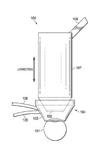
[0028] FIGURE 1 is a schematic representation of a docking apparatus 100 for
femtosecond
laser ophthalmic surgery. As shown, a typical docking apparatus 100 includes a
suction ring
103 which is suctioned to a patient's eye 101, where a patient interface 104
fits within the
suction ring 103. A series of two vacuums, first vacuum 105 and second vacuum
106 are
-5-
CA 03016275 2018-08-30
WO 2017/191486
PCT/IB2016/052493
attached to the suction ring and are used to provide suction to the patient's
eye 101 at
appropriate times.
[0029] During docking, the suction ring 103 is suctioned to the patient's eye
101 so that the
suction ring is in contact with eye 101. Once the suction ring 103 has been
properly
positioned on the eye 101, first vacuum 105 is turned on to provide initial
suction. The
docking apparatus 100 further includes a suction cone 107 that fits into the
suction ring 103.
The suction cone includes a flat glass plate 102. The suction cone 107 may be
lowered in the
z direction by a control device 108 into the patient interface 104 within the
suction ring 103,
until the flat glass plate 102 makes contact with the eye 101. Alternatively,
the suction cone
107 may remain stationery, while a patient's eye 101 is moved upwards towards
the suction
cone 107. This can be done, for example, by moving the patient upwards towards
the suction
cone 107. Once the glass plate 102 of the suction cone 107 makes contact with
the eye 101,
the suction cone 107 may be moved upwards in the z direction along with the
eye 101 to
provide different levels of contact with the patient's eye 101 until suction
cone 107 reaches a
threshold point in the z direction. After this threshold point is reached,
second vacuum 106 is
switched on and the suction cone 107 becomes firmly attached to the eye 101 by
suctioning
to the suction ring 103. This firm attachment to the eye 101 provides enough
pressure to
flatten the cornea of the patient's eye 101 because all or part of the cornea
is within suction
ring 103, a process which is known as applanation of the cornea. Once
applanation occurs,
docking is complete.
[0030] Proper placement of the suction cone during docking is important for
successful
ophthalmic surgery. However, in prior systems, the user was forced to rely on
experience
and perception to dock the suction cone properly, which makes it more
difficult to attain
proper placement and results in more placement errors. The present disclosure
provides a
system for femtosecond laser ophthalmic surgery in which the system contains a
docking
apparatus, such as that described above, and a measuring device to measure the
position of
the suction cone in the z direction during docking. The measuring device may
include or be
connected to a processor that uses the measured position to create a pictorial
representation,
histogram, or other graph of the position of the suction cone in the z
direction or in relation to
the cornea or another reference point on the eye, or of data relating to the
measured position,
such as the load of the suction cone on the eye or applanation of the cornea.
One or more of
these pictorial representations, histograms, or other graphs may be presented
in real time
-6-
CA 03016275 2018-08-30
WO 2017/191486
PCT/IB2016/052493
during the femtosecond laser ophthalmic surgery. In addition, a single image
or display may
include more than one of these items. For instance, a single image may include
both a
pictorial representation and a histogram.
[0031] Referring now to FIGURE 2, a schematic representation of elements of a
system for
femtosecond laser ophthalmic surgery 200 including a docking apparatus 100,
such as that of
FIGURE 1, is provided. Such a system may be used to measure the position of
suction cone
107 in the z direction and it may use the measured position to present a
pictorial
representation, histogram, or other graph based on the measured position. As
shown, the
disclosed docking apparatus includes a suction cone 107; a control device 108
that is used to
move the suction cone 107 up and down in the z direction; a measuring device
201 which
measures the position of the suction cone 107; a processor 202 or equivalent
programmed
processing device that is included in or connected to the measuring device 201
and which
processes data relating to the measured positions to create a pictorial
representation, a
histogram, or other graph of or based on the position of the suction cone 107
in the z
direction, and which transmits a pictorial representation, histogram, or other
graph to a
display. The display may be in the form of a screen 203 or a head-up display
204. The
system may present the pictorial representation, histogram, or other graph of
or based on the
position of the suction cone 107 in the z direction in real time to users so
that they may adjust
the position of the suction cone 107 accordingly using the control device 108.
Real time may
mean in less than half a second, in less than one second, or otherwise in less
than the normal
reaction time of a user of control device 108 based upon visual information.
[0032] Measuring device 201 may include lights barriers, switches, and
distance measuring
devices to measure the position of the suction cone 107 in the z direction. By
way of non-
limiting example, the distance measuring device may have a high resolution, as
the overall
acceptable moveable distance of suction cone 107 in the z direction is on the
order of
millimeters or centimeters. By way of non-limiting example, the light barriers
and switches
may only be able to measure or to otherwise react to the suction cone position
at discrete
positions. Measuring device 201 may also measure the position of the eye, the
cornea,
another reference point in the eye, or even an external reference point.
Processor 202 may
then use the measured position or positions to create a pictorial
representation of the position
of the suction cone 107 in the z direction as compared to the eye 101, or to
perform
calculations or other processing functions resulting in a histogram or other
graph.
-7-
CA 03016275 2018-08-30
WO 2017/191486
PCT/IB2016/052493
[0033] FIGURES 3A, 3B and 3C provide a schematic representation 300 of the
movement of
suction cone 107 in the z direction during docking on an eye 101 from a
position 301 through
at least some of a series of positions 302, 303, 304 and 305. In FIGURE 3A,
suction cone 107
is at position 302. In FIGURE 3B, suction cone 107 has moved upward in the z
direction to
position 303. In FIGURE 3C, suction cone 107 has moved upward in the z
direction to
position 305. The A portion of the patient's eye 101 moves upward in the z
direction as well.
[0034] Referring to FIGURES 1, 2, and 3, when the suction cone 107 is first
lowered into the
suction ring 103 it is moved to rest position 301, where it is in contact with
the eye 101. Once
the suction cone 107 is at rest position 301, in contact with the eye 101, the
position of the
suction cone in the z direction may be measured by measuring device 201, which
transmits
the measured position in the z direction to processor 202, which then uses
data relating to the
measured position in the z direction to create a pictorial representation of
the suction cone
107's position in the z direction that is presented on the display 203/204 for
a user, as
described further with reference to FIGURE 4.
[0035] Next, the suction cone 107 is typically moved upward in the z
direction, together with
the patient's eye 101. There are a number of threshold positions that the
suction cone 107
may reach when moving upwards in the z direction. Surgical system 200 may
measure when
each threshold position is reached and present related information, such as a
threshold marker
on the pictorial representation 300. The presentation may be in real time.
[0036] Specifically, as the suction cone 107 moves upwards, together with the
eye, it reaches
position 302, where contact with the eye 101 is considered low. When this
position is
measured via the measuring device 201, the display 203/204 will show that the
suction cone
107 is in a low contact position with the eye 101, or "EC Low." A schematic
representation
of the suction cone 107 at this threshold position is shown in FIGURE 3A.
[0037] Suction cone 107 then continues to travel upwards in the z direction
until the
measuring device 201 measures that the suction cone 107 has reached a position
303 of high
contact with the eye, or "EC High" 303, this is also presented. A schematic
representation of
the suction cone 107 at this threshold position is shown in FIGURE 3B. The
second vacuum
106, switches on, either automatically or because the user activates it, and
the suction cone
107 becomes firmly attached to the eye 101 by suctioning to the suction ring
103, which has
already been suctioned to the eye 101 by the suction from the first vacuum
105. Once the
-8-
CA 03016275 2018-08-30
WO 2017/191486
PCT/IB2016/052493
suction cone 107 reaches position 303, and second vacuum 106 is initiated,
applanation of the
cornea occurs. The suction cone 107 may then continue to move upward within
position 304,
which is represented as a shaded area rather than a line because any position
in the z direction
within that range is an acceptable position. Position 304 is known as the
ideal work area
where there is enough pressure on the eye 101 for applanation, but not so much
pressure as to
squeeze the eye. As the suction cone 107 continues to move upwards within the
ideal work
area position 304, the position of suction cone 107 in the z direction may be
presented to the
user in real time. If the suction cone 107 moves upwards in the z direction
past the ideal work
area position 304, there is a danger that too much pressure could squeeze the
eye 101.
Therefore, a threshold limit position 305, known as the z stop limit is
defined within the z
direction. A schematic representation of the suction cone 107 at this
threshold position is
shown in FIGURE 3C. When the measuring device 201 measures that the suction
cone 107
has reached this position 305, this is also presented, often in real time. The
user or the system
should halt all further upward movement in the z direction. System 200 may
further prevent
further upward movement in the z direction, particularly if processor 202 is
connected to
control device 108. Instead of stopping further upward movement only when the
suction cone
107 has reached the z stop limit position 305, the system may also be
configured to
automatically hold suction cone 107 still in a defined position within the
ideal work are 304.
[0038] FIGURE 4 is an example screen display 400 of a pictorial representation
showing the
position of suction cone 107 during docking on an eye 101 in femtosecond laser
ophthalmic
surgery as depicted in FIGURE 3. As shown, the screen display 400 provides a
pictorial
representation 401 of the suction cone 107 as well pictorial threshold markers
403 through
406 which correspond to threshold positions 302 through 305. As the suction
cone 107 is
moved up or down in the z direction during docking, the pictorial
representation of the
suction cone 401 will show when the actual suction cone 107 reaches the
threshold positions
via the corresponding pictorial threshold markers. When the suction cone 107
has reached a
threshold position 302 of low contact with the eye 101, "EC Low," the display
400 will show
the pictorial representation 401 with the suction cone at threshold marker
403. When the
suction cone 107 has reached a threshold position 303 of high contact with the
eye 101, "EC
High," the display 400 will show the pictorial representation 401 of the
suction cone at
threshold marker 404. At this threshold position, the suction cone 107 has
reached the ideal
work area 304 and the second vacuum 106 will be initiated to provide suction
for applanation
-9-
CA 03016275 2018-08-30
WO 2017/191486
PCT/IB2016/052493
of the cornea. While the suction cone 107 remains within the ideal work area
304, the display
400 will show the pictorial representation 401 of the suction cone within
threshold marker
406. If the suction cone 107 has reached z stop limit threshold position 305,
the display 400
will show the pictorial representation 401 of the suction cone at threshold
marker 405. In
addition, a warning indicator, such as a flashing light, a change in color of
all or a component
of the pictorial representation, or a text message on display 400 may occur.
[0039] Pictorial representation 401 may present more than one threshold marker
403-406
simultaneously. For instance, it may present all threshold markers 403-406
simultaneously as
depicted in FIGURE 4. However, pictorial representation 401 may also present
only one
threshold marker, such as the threshold marker closest to the measured
position of the suction
cone. Pictorial representation 401 may also present only a subset of threshold
markers 403-
406 simultaneously. For instance, it may present the threshold marker most
recently passed
and the next approaching threshold marker, or it may present the threshold
marker closest to
the measured position and another significant threshold marker, such as the
threshold marker
405 corresponding to the z stop position. If all threshold markers are not
displayed
simultaneously, one or more of those that are displayed may change over time
during the
surgery as the suction cone moves in the z direction.
[0040] Measurements made with measuring device 201 may also be used to
construct a
histogram 500 showing the position of a suction cone in the z direction during
docking on an
eye in femtosecond laser ophthalmic surgery, such as that shown in FIGURE 5.
In order to
construct such a histogram, the data relating to the measured position is
recorded so that the
histogram indicates suction cone 107's movement in the z direction over time.
The
histogram may be updated in real time or shown as a static histogram at the
end of the
treatment.
[0041] In addition to being used to present the position of the suction cone
107 in the z
direction during docking on a cornea, the positions measured by measuring
device 201 may
also be used to determine the curved interface of the cornea during docking
and initiation of
and level of applanation of the cornea. This information may also be presented
in real time.
[0042] Referring now to FIGURE 6, applanation 600 of a cornea during docking
in
femtosecond laser ophthalmic surgery is depicted. As shown, after initial
contact with the
patient's eye 101, as the suction cone 107 moves upwards in the z direction,
the shape of the
-10-
CA 03016275 2018-08-30
WO 2017/191486
PCT/IB2016/052493
cornea changes as the suction cone moves upwards in the z direction and
applies more
pressure on the eye. When there is no eye contact with the suction cone 107,
there is no
corneal deformation and any pictorial representation will present the eye 101
with no corneal
deformation 601. As the suction cone 107 is moved upwards with the eye 101,
applanation is
initiated when there is minimal corneal deformation 602, which may also be
presented.
When full applanation has occurred 603, and the cornea is sufficiently flat
for femtosecond
laser treatment to begin, this may also be presented. As an alternative to
presenting a
pictorial representation of applanation as depicted in FIGURE 6, a display may
instead
present another indicator of the degree of applanation, such as an indicator
of when
applanation is initiated and an indicator of when full applanation has
occurred.
[0043] Suction cone 107 positions measured by measuring device 201 may also be
used by
processor 202 to calculate other information regarding the eye, which may be
presented in a
pictorial representation or a graph. For instance, the example display of
FIGURE 7 presents
a pictorial representation 700 of the load resting on the eye 101 as a
function of the z
direction position of suction cone 107 during docking. In addition to
presenting a pictorial
representation of the position of the suction cone 107 in the z direction
during docking, the
positions measured by the measuring device 201 may also be used to determine
the load
amount 701 on eye 101 from the suction cone 107 resting on eye 101 at any
given time,
including in real time. This load may, for instance, be measured in grams or
another load
unit, or it may simply be depicted in relative amounts, for instance by color,
as acceptable,
approaching unacceptable, or unacceptable, or as a bar graph, such as that of
FIGURE 8. As
shown in FIGURE 7, after initial contact with the eye 101, as the suction cone
107 moves
upwards in the z direction, the measurement of the z direction position of the
suction cone
107 may be converted to a load amount 701.
[0044] Referring now to FIGURE 9, a method 900 for docking in femtosecond
laser
ophthalmic surgery, as described herein, is depicted as a flowchart. Method
900 may be used
in conjunction with the systems and apparatus described above.
[0045] Method 900 may be used to ensure that a suction cone is within the
ideal work area
for femtosecond laser treatment. Certain operations described in method 900
may be optional
or may be rearranged in variant femtosecond laser ophthalmic surgeries using
the systems
and apparatuses of this disclosure.
-11-
CA 03016275 2018-08-30
WO 2017/191486
PCT/IB2016/052493
[0046] Method 900 may begin, at step 901, by positioning the suction cone
above a patient's
eye. At step 902, the suction cone is moved downwards in the z direction using
a control
device until it makes contact with the patient's eye.
[0047] At step 903, a measuring device measures the position of suction cone
and presents
information related to the position on a display, so that the user may detect
if the suction cone
has made contact with the patient's eye. If eye contact has been made, the
method moves to
step 904. If eye contact has not yet been made, step 902 is continued until
eye contact is
made.
[0040] Once eye contact has been made, at step 904, the suction cone along
with the patient's
eye are moved upwards in the z direction using the control device. At step
905, the measuring
device measures the position of the suction cone in the z direction. At step
906, the measuring
device transmits data relating to the measured positions to a processor, which
uses the data to
create a pictorial representation, histogram, or other graph based on the
data, which are
displayed on a display, optionally in real time. A pictorial representation
may also present
one or more threshold markers and show the position of the docking cone with
respect to
these threshold markers. The threshold markers may include a threshold marker
corresponding to at least one of a low eye contact threshold position, a high
eye contact
threshold position, an ideal work area threshold position, and a z stop limit
threshold position.
[0049] At step 907, if the suction cone has reached the high eye contact
threshold position,
suction is applied by a second vacuum to initiate applanation of the patient's
cornea, step
908. If this level has not yet been reached, steps 904-906 are repeated until
the high eye
contact threshold point is reached. Once applanation is initiated, at step
909, the suction cone
may be moved upwards in the z direction within the ideal work area until it
reaches the z stop
limit threshold position. At step 910, if the suction cone has reached the z
stop limit threshold
position, all further movement of the suction cone in the upwards z direction
will be stopped,
step 911.
[0050] In addition to measurements of the suction cone position, the measuring
device may
also measure the position of the eye, or of another reference point. Data
relating to these
positions may also be used to present a pictorial representations, histogram,
or other graph
based on the data.
-12-
CA 03016275 2018-08-30
WO 2017/191486
PCT/IB2016/052493
[0051] The above disclosed subject matter is to be considered illustrative,
and not restrictive,
and the appended claims are intended to cover all such modifications,
enhancements, and
other embodiments which fall within the true spirit and scope of the present
disclosure. Thus,
to the maximum extent allowed by law, the scope of the present disclosure is
to be
determined by the broadest permissible interpretation of the following claims
and their
equivalents, and shall not be restricted or limited by the foregoing detailed
description.
-13-