Note: Descriptions are shown in the official language in which they were submitted.
CA 03016558 2018-08-31
WO 2017/151968 PCT/US2017/020516
HEATER-ACTUATED FLOW BYPASS
FIELD
[0001] The present disclosure relates to heating and sensing
systems
for fluid flow applications, for example vehicle exhaust systems, such as
diesel
exhaust and aftertreatment systems.
BACKGROUND
[0002] The statements in this section merely provide background
information related to the present disclosure and may not constitute prior
art.
[0003] The use of physical sensors in transient fluid flow
applications
such as the exhaust system of an engine is challenging due to harsh
environmental
conditions such as vibration and thermal cycling. One known temperature sensor
includes a mineral insulated sensor inside a thermowell that is then welded to
a
support bracket, which retains a tubular element. This design, unfortunately,
takes a
long amount of time to reach stability, and high vibration environments can
result in
damage to physical sensors.
[0004] Physical sensors also present some uncertainty of the actual
resistive element temperature in many applications, and as a result, large
safety
margins are often applied in the design of heater power. Accordingly, heaters
that
are used with physical sensors generally provide lower watt density, which
allows a
lower risk of damaging the heater at the expense of greater heater size and
cost
(same heater power spread over more resistive element surface area).
[0005] Moreover, known technology uses an on/off control or PID
control from an external sensor in a thermal control loop. External sensors
have
inherent delays from thermal resistances between their wires and sensor
outputs.
Any external sensor increases the potential for component failure modes and
sets
limitations of the any mechanical mount to the overall system.
[0006] One application for heaters in fluid flow systems is vehicle
exhausts, which are coupled to an internal combustion engine to assist in the
reduction of an undesirable release of various gases and other pollutant
emissions
into the atmosphere. These exhaust systems typically include various after-
treatment devices, such as diesel particulate filters (DPF), a catalytic
converter,
selective catalytic reduction (SCR), a diesel oxidation catalyst (DOC), a lean
NOx
1
CA 03016558 2018-08-31
WO 2017/151968 PCT/US2017/020516
trap (LNT), an ammonia slip catalyst, or reformers, among others. The DPF, the
catalytic converter, and the SCR capture carbon monoxide (CO), nitrogen oxides
(NO), particulate matters (PMs), and unburned hydrocarbons (HCs) contained in
the
exhaust gas. The heaters may be activated periodically or at a predetermined
time
to increase the exhaust temperature and activate the catalysts and/or to burn
the
particulate matters or unburned hydrocarbons that have been captured in the
system.
[0007] The heaters are generally installed in exhaust pipes or
components such as containers of the exhaust system. The heaters may include a
plurality of heating elements within the exhaust pipe and are typically
controlled to
the same target temperature to provide the same heat output. However, a
temperature gradient typically occurs because of different operating
conditions, such
as different heat radiation from adjacent heating elements, and exhaust gas of
different temperature that flows past the heating elements.
[0008] The life of the heater depends on the life of the heating
element
that is under the harshest heating conditions and that would fail first. It is
difficult to
predict the life of the heater without knowing which heating element would
fail first.
To improve reliability of all the heating elements, the heater is typically
designed to
be operated with a safety factor to reduce and/or avoid failure of any of the
heating
elements. Therefore, the heating elements that are under the less harsh
heating
conditions are typically operated to generate a heat output that is much below
their
maximum available heat output.
SUMMARY
[0009] In one form of the present disclosure, a fluid control
system is
provided that includes a first flow channel, a second flow channel in fluid
communication with the first flow channel, a heater disposed proximate at
least one
of the first flow channel and the second flow channel, and a fluid control
device
disposed upstream from the first and second flow channel. The fluid control
device
is operable to be actuated when the heater is turned on, thereby changing a
fluid
flow rate in at least one of the first flow channel and the second flow
channel.
Actuating the fluid control device in one form causes fluid to flow through
the second
flow channel, in another form prevents fluid from flowing through the first
flow
2
CA 03016558 2018-08-31
WO 2017/151968 PCT/US2017/020516
channel when fluid is flowing through both channels, and in another form
partially re-
directs a portion of the fluid flow through the second flow channel.
[0010] In another form, an exhaust system of an engine providing
exhaust to an exhaust fluid flow pathway is provided that includes at least
one
exhaust aftermath treatment system disposed in the exhaust fluid flow pathway.
A
bypass conduit is coupled to the exhaust fluid flow pathway at an upstream
location
from at least one exhaust aftertreatment system. A heater is disposed within
the
bypass conduit.
[0011] In still another form, an exhaust system is provided that
includes
at least one exhaust aftertreatment system provided in an exhaust fluid flow
pathway
and a regeneration device disposed downstream from at least one exhaust
aftertreatment system. The regeneration device includes at least one valve,
wherein
actuating the regeneration device restricts the exhaust fluid flow.
[0012] In yet another form, the teachings of the present disclosure
may
be applied to a fluid conduit without a bypass. Accordingly, a fluid heating
system is
provided that comprises a fluid conduit, a heater disposed within the fluid
conduit,
and a mechanism operable to be actuated when the heater is turned on to change
at
least one of a shape, position, orientation, and location of the heater.
[0013] Further areas of applicability will become apparent from the
description provided herein. It should be understood that the description and
specific
examples are intended for purposes of illustration only and are not intended
to limit
the scope of the present disclosure.
DRAWINGS
[0014] In order that the disclosure may be well understood, there
will
now be described various forms thereof, given by way of example, reference
being
made to the accompanying drawings, in which:
[0015] FIG. 1 is schematic diagram of a diesel engine and exhaust
aftertreatment system in which the principles of the present disclosure are
applied;
[0016] FIG. 2 is a schematic view of a flow control device provided
in
an upstream exhaust conduit according to the teachings of the present
disclosure;
[0017] FIG. 3 is a side view of the flow control device of FIG. 2;
[0018] FIG. 4 is a front view of the flow control device of FIG. 2;
3
CA 03016558 2018-08-31
WO 2017/151968 PCT/US2017/020516
[0019]
FIG. 5 is a schematic view of another form of a flow control
device provided in an upstream exhaust conduit according to the teachings of
the
present disclosure;
[0020]
FIG. 6 is a schematic view of yet another form of a flow control
device in a closed position provided in an upstream exhaust conduit according
to the
teachings of the present disclosure;
[0021]
FIG. 7 is a schematic view of the flow control device of FIG. 6 in
an open position;
[0022]
FIG. 8 is a schematic view of an exhaust system according to
another form of the present disclosure;
[0023]
FIG. 9 is a schematic view of a bypass channel where flow
control devices are installed at an inlet and an outlet of the bypass channel
according to the teachings of the present disclosure; and
[0024]
FIG. 10 is a schematic view of still yet another form of an
exhaust system according to of the teachings of the present disclosure.
[0025] The
drawings described herein are for illustration purposes only
and are not intended to limit the scope of the present disclosure in any way.
DETAILED DESCRIPTION
[0026] The
following description is merely exemplary in nature and is
not intended to limit the present disclosure, application, or uses. It should
be
understood that throughout the drawings, corresponding reference numerals
indicate
like or corresponding parts and features.
[0027]
Referring to FIG. 1, an exemplary engine system 10 generally
includes a diesel engine 12, an alternator 14 (or generator in some
applications), a
turbocharger 16, and an exhaust aftertreatment system 18. The
exhaust
aftertreatment system 18 is disposed downstream from the turbocharger 16 for
treating exhaust gases from the diesel engine 12 before the exhaust gases are
released to atmosphere. The exhaust aftertreatment system 18 can include one
or
more additional components, devices, or systems operable to further treat
exhaust
fluid flow to achieve a desired result. In the example of FIG. 1, the exhaust
aftertreatment system 18 includes a heating system 20, a diesel oxidation
catalyst
(DOC) 22, a diesel particulate filter device (DPF) 24, and a selective
catalytic
reduction device (SCR) 26. The heating system 20 includes a heater assembly 28
4
CA 03016558 2018-08-31
WO 2017/151968 PCT/US2017/020516
disposed upstream from the DOC 22, and a heater control device 30 for
controlling
operation of the heater assembly 28. The exhaust aftertreatment system 18
further
includes an upstream exhaust conduit 32 that receives the heater assembly 28
therein, an intermediate exhaust conduit 34 in which the DOC 22 and DPF 24 are
received, and a downstream exhaust conduit 36 in which the SCR is disposed.
Although a diesel engine 12 is shown, it should be understood that the
teachings of
the present disclosure are also applicable to a gasoline engine and other
fluid flow
applications. Therefore, the diesel engine application should not be construed
as
limiting the scope of the present disclosure.
[0028] The DOC 22 is disposed downstream from the heater assembly
28 and serves as a catalyst to oxide carbon monoxide and any unburnt
hydrocarbons in the exhaust gas. In addition, The DOC 22 converts nitric oxide
(NO) into nitrogen dioxide (NO2). The DPF 24 is disposed downstream from the
DOC 22 to remove diesel particulate matter (PM) or soot from the exhaust gas.
The
SCR 26 is disposed downstream from the DPF 24 and, with the aid of a catalyst,
converts nitrogen oxides (N0x) into nitrogen (N2) and water. A urea water
solution
injector 27 is disposed downstream from the DPF 24 and upstream from the SCR
26
for injecting urea water solution into the stream of the exhaust gas. When
urea
water solution is used as the reductant in the SCR 18, NOx is reduced into N2,
H20
and CO2.
[0029] It should be understood that the engine system 10
illustrated
and described herein is merely exemplary, and thus other components such as a
NO adsorber or ammonia oxidation catalyst, among others, may be included,
while
other components such as the DOC 22, DPF 24, and SCR 26 may not be employed.
Further, although a diesel engine 12 is shown, it should be understood that
the
teachings of the present disclosure are also applicable to a gasoline engine
and
other fluid flow applications. Therefore, the diesel engine application should
not be
construed as limiting the scope of the present disclosure. Such variations
should be
construed as falling within the scope of the present disclosure.
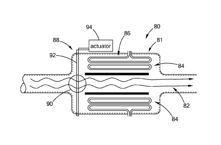
[0030] Referring to FIG. 2, one form of the present disclosure has
a
fluid control system 80 disposed in an upstream exhaust conduit 81. The
upstream
exhaust conduit 81 in one form defines a first flow channel 82 and a second
flow
channel 84 surrounding the first flow channel 82. The first flow channel 82
can be an
inner flow channel and the second flow channel 84 an outer flow channel
CA 03016558 2018-08-31
WO 2017/151968 PCT/US2017/020516
surrounding the first/inner flow channel 82. In the example of FIG. 2, the
second
flow channel 84 is in fluid communication with the first flow channel 82. The
first and
second flow channels 82, 84 are in a fluid flow path of the exhaust system,
such as
the exhaust system of FIG. 1. A heater 86 is disposed in the second flow
channel
84. A fluid control device 88 is provided upstream of the first and second
flow
channel 82, 84 to control the flow path of the exhaust gas. The fluid control
system
80 further includes an actuator 94 coupled to the fluid control device 88 and
adapted
to actuate the fluid control device 88 when the heater 86 is turned on. The
fluid
control device 88 may direct the exhaust gas through both the first and second
flow
channels 82, 84 during normal engine operation when the heater 86 is not
activated.
The fluid control device 88 is actuated when the heater 86 is turned on.
Actuating
the fluid control device 88 causes the first flow channel 82 to change a fluid
flow rate
in at least one of the first flow channel 82 and the second flow channel 84.
Actuating
the fluid control device 88 in one form causes fluid to flow through the
second flow
channel 84, in another form prevents fluid from flowing through the first flow
channel
82 when fluid is flowing through both channels, and in another form partially
re-
directs a portion of the fluid flow through the second flow channel 84.
[0031] In another form of the present disclosure, the exhaust gas
can
be directed through only one of the first flow channel 82 and the second flow
channel
84 during normal engine operation. In this configuration, the second flow
channel 82
functions as a bypass channel. When the heater 86 is not actuated, the exhaust
gas
is directed through only the first flow channel 82. When the heater 86 is
actuated,
the exhaust gas is directed through only the second flow channel 84. A fluid
control
device 88 is provided upstream of the first and second flow channels 82, 84 to
control the flow path of the exhaust gas.
[0032] Referring to FIGS. 2 through 4, in one form of the present
disclosure, the flow control device 88 includes a flapper member 90, a support
member 92. The support member 92 can be in the form of a bar extending from
opposing ends of the flapper member 90 and the actuator 94. The flapper member
90 is disposed upstream from the first and second flow channels 82, 84. In one
form, flapper member 90 defines a plate body having a position normal to the
flow of
exhaust gas. When the heater 86 is not activated, the flapper member 90 is
positioned such that the normal direction is perpendicular to the longitudinal
axis of
the first flow channels 82 and the exhaust gas is allowed to pass through the
first
6
CA 03016558 2018-08-31
WO 2017/151968 PCT/US2017/020516
flow channel 82. When the heater 86 is activated, the flapper member 90 is
positioned such that its normal direction is parallel to the longitudinal axis
of the first
flow channel 82 to close the first flow channel 82.
[0033] The flow control device 88 is actuated to position the
flapper
member 90 in a different position based on the status of the heater 86
disposed in
the second flow channel 84. When regeneration is necessary, the heater 86 is
turned on to heat the exhaust gas flowing through the heater 36. The heat from
the
heater 86 causes the flow control device 88 to be actuated to direct the flow
the
exhaust gas through the second flow channel 84, thereby controlling the flow
rate of
the exhaust gas.
[0034] Optionally, the flow control device 88 may include one or
more
actuating surfaces 96 that can cause actuation of the flow control device 88
by
thermal energy. The thermal energy can be provided through a number of
sources,
including by way of example, heat from the heater 86, a reaction to a change
in
temperature of the heater, the exhaust gas, a reaction to a change in
temperature of
the exhaust gas, differential thermal expansion, and combinations thereof.
When
regeneration is necessary and the heater 86 is turned on, the actuating
surface 96
faces the heater 86 and thus is heated. The heated actuating surface 96 may
transmit a signal to the actuator 94, causing the actuator 94 to position the
flow
control device 88 to change the flow path and/or flow rate of the exhaust gas
as
previously described.
[0035] The flow control device 80 may include a flapper valve,
butterfly
valve, or a similar structure. The actuator 94 may include a material such as
a
shape memory alloy that changes shape in response to heat or temperature
change.
In one form of the present disclosure, the flapper member 94 can be made of
the
shape memory alloys that change shape in response to a temperature or
temperature change associated with heater operation. The flow control device
80
can change its position due to the changed shape of the flapper member 94. In
another form, the flapper member 94 can be made of bi-metallic construction
where
a temperature associated with heater operation causes a displacement for
actuating
flow control device 90. The actuation of the flow control device 90 may be
directly
actuated by the actuating surface 96 or through the external actuator 94.
[0036] Referring to FIG. 5, another form of a flow control device
100 is
provided according to the present disclosure. The flow control device 100
includes a
7
CA 03016558 2018-08-31
WO 2017/151968 PCT/US2017/020516
pivoting member 102 and an actuating member 104. As shown, the actuating
member 104 is disposed proximate a wall of the first flow channel 82 and in
contact
with the heater 86. The pivoting member 102 is pivotably connected to the
actuating
member 84 and is pivotable to move between an open position A (where the first
flow channel 82 is open) and a closed position B (where the first flow channel
82 is
closed). The pivoting member 102 can further be operable to pivot and reduce
fluid
flow through first flow channel 82 by being positioned somewhere between a
fully
open and a fully closed position. In one form, when the heater 86 is not
actuated,
the pivoting member 102 is in the open position to allow the exhaust gas to
flow
through the first flow channel 82. When regeneration is necessary and the
heater 86
is turned on, heat is applied to the actuating member 104 and causes the
actuating
member 104 to change its shape. The changed shape triggers the pivoting member
102 to move from the open position A to the closed position B or somewhere in
between. In a fully closed position B, the first flow channel 82 is closed
thereby
preventing fluid flow through the first flow channel 82 and opening the second
flow
channel 84 in which the heater 86 is disposed. As a result, the exhaust gas is
directed through the second flow channel 84 and heated by the heater 86.
[0037] Referring to FIGS. 6 and 7, a flow control device 120
according
to another form of the present disclosure includes multiple flexing members
122 that
may be of a bi-metallic construction and mounted proximate a wall that defines
the
first flow channel 82 and positioned near the heater 86. The flexing members
122
are movable between an open position A (where the first flow channel 84 is
open)
and a closed position B (where the first flow channel 84 is closed). This
includes
various positions between position A and position B. When the heater 86 is not
turned on, the flexing members 122 can be in the open position A to open the
first
flow channel 82 and to block or reduce fluid flow through the second flow
channel
84. When regeneration is necessary and the heater 86 is actuated, the flexing
members 122 change their shape and move toward each other to the closed
positon
B to close or reduce fluid flow through the first flow channel 82. The exhaust
fluid is
then directed through the second flow channel 84 and is heated by the heater
86
therein.
[0038] The flow control device 120 can be directly actuated by the
operation of the heater 86 without using a separate actuator, such as a motor,
solenoid, air cylinder or hydraulic cylinder, and associated control logic.
Therefore,
8
CA 03016558 2018-08-31
WO 2017/151968 PCT/US2017/020516
an opening through the exhaust pipe may not be needed in order to connect the
flow
control device 120 to an external actuator and thus leakage of exhaust gas
through
such an opening would not occur. The flow control device 120 of this form can
reduce manufacturing costs and structural complexity.
[0039] Referring to FIG. 8, an engine system 150 is provided in
accordance with another form of the present disclosure and includes a diesel
engine
152, an exhaust aftertreatment system, including various exhaust treatment
units
154, 156, 158, and an SCR 160. The various exhaust treatment units 154, 156,
158
may be any combination of a catalytic converter, a DPF, a DOC, an LNT, an
ammonia slip catalyst, or reformers, depending on the application. The engine
system 150 further includes a bypass conduit 162 coupled to the exhaust fluid
flow
having an inlet 164 disposed upstream of the various exhaust treatment units
154,
156, 158 and an outlet 166 disposed at a downstream of the various exhaust
treatment units 154, 156, 158, which is also an inlet of the SCR 160.
[0040] Referring to FIG. 9, a heater 168 is provided in the bypass
conduit 162. Flow control devices 170 as shown in FIGS. 2 to 7 are disposed at
the
inlet 164 and outlet 166 of the bypass conduit 162. In one form, during normal
engine operation, the bypass conduit 162 is closed. When regeneration is
necessary, the flow control devices 170 may open the inlet 164 of the bypass
conduit
162 so that the exhaust gas is redirected through the bypass conduit 162 to be
heated by the heater 168. Furthermore, when regeneration is necessary, the
flow
control device 170 positioned near the outlet 166 of the bypass conduit 162
may
close the outlet 166 of the bypass conduit 162 to allow for the exhaust gas to
be
heated by the heater 168. By providing a bypass conduit 162 separate from the
main exhaust path and by providing the heater 168 in the bypass conduit 162,
the
exhaust gas can more smoothly flow in the bypass conduit 162. Therefore,
backpressure caused by the presence of the heater 168 in the main flow path as
shown in FIGS. 2 to 7 can be reduced.
[0041] Referring to FIG. 10, the exhaust system 180 may include an
exhaust aftertreatment system as shown in FIG. 8, and a regeneration device
182
including at least one valve 184 disposed downstream of an SCR 186 and a DPF
188. When regeneration is activated, the regeneration device 182 may close an
outlet of the exhaust pipe downstream from the SCR 186. By closing the outlet,
the
exhaust gas remains in the DPF 188 and SCR 186 and increases the gas pressure
9
CA 03016558 2018-08-31
WO 2017/151968 PCT/US2017/020516
inside the DPF 188 and the SCR 186. The increased pressure causes the
temperature of the exhaust gas to increase, resulting in burning of the
particles in the
DPF 188 and facilitating SCR process in the SCR unit 186.
[0042] The teachings of the present disclosure may also be used
within
a single conduit or fluid flow channel without being limited to a bypass
channel. A
heater actuated mechanism may be employed that would change the position,
orientation, angle of attack or other geometric characteristic of the heater
to allow it
to improve heat transfer when the heater is on and to allow it to shift into a
position
that reduces drag/backpressure when the heater is off. Such a mechanism may be
attached directly to the heater or parts of the heater (e.g. a metal member
attached
directly to the heater surface that would move the heater by differential
thermal
expansion). Such a mechanism may include any of the fluid control devices and
materials as disclosed herein, such as a shape memory alloy.
[0043] In other forms, each of the elements illustrated herein can
be
positioned or reconfigured such that they are aligned with the fluid flow
rather than
being arranged across the flow. Also, another separate bypass could be
employed
to divert flow around the heater, similar to a piping system. These variations
and
configurations should be construed as falling within the scope of the present
disclosure.
[0044] The description of the disclosure is merely exemplary in
nature
and, thus, variations that do not depart from the substance of the disclosure
are
intended to be within the scope of the disclosure. Such variations are not to
be
regarded as a departure from the spirit and scope of the disclosure.