Note: Descriptions are shown in the official language in which they were submitted.
CA 03016722 2018-09-06
1
Solar energy roof tile having a length-variable connecting element
The present invention relates to a solar energy roof tile to produce
electrical
and thermal energy from solar energy, wherein the solar energy roof tile
essentially has the shape of conventional roof tiles.
Solar-thermic, especially the provision of hot water, is the most widespread
technique for utilization of solar radiation, wherein solar collectors are
used
to heat fluids. The solar radiation meanwhile enters an absorber surface of
the collector to heat it. The generated heat will be transferred to a flow-
through medium, generally a fluid or even air. The medium heated by the
solar radiation is usually passed to a hot water storage tank by a circulating
pump, wherein the generated heat is transferred from the heated medium
(e.g. a carrier fluid) to the industrial water or drinking water in the hot
water storage tank via a heat exchanger. In doing so, the medium cools
down and will subsequently be recycled back to the collector.
If a fluid is used as a medium, a mixed antifreeze liquid and water is
especially suitable. Alternatively, heating-circuit water itself may be
pumped into the collector and may be heated therein. Even in this case,
drinking water may be heated via the heat exchanger.
Photovoltaics is also a widespread technique for the utilization of the solar
radiation. The solar radiation enters a photovoltaic module with solar cells.
Said solar cells convert the energy of the sunlight into electrically usable
energy. The conversion von solar energy into electrically usable energy is
well known and will not be described in further details.
Utilization of roof surfaces for affixing solar collectors is well-suited.
Commercially available solar collectors are mostly applied to already
completed roofs in addition. Fastening elements are often required to be
mounted through the roofing sheet onto the roof supporting structure,
wherein fastening is required to be stormproof and is preferably also
CA 03016722 2018-09-06
2
required to be corrosion-protected. When perforating the conventional
roofing sheet, sealing and subsequent tightness problems inevitably will
arise. In Addition, increase of the roof load occurs, often resulting in a
necessary reinforcement in the roof trusses. Moreover, such solar collectors
negatively interfere with the optical appearance of the roof.
Alternatively, solar thermal or photovoltaic roof tiles are known, which are
used instead of the generally used roof tiles, roof tiles or roofing stone
articles. Solar energy roof tiles also comprise an absorber for receiving the
solar energy and are passed through by a medium, preferably a fluid, which
becomes heated accordingly. Photovoltaic roof tiles, at the top, i.e. facing
the sun, include photovoltaic modules or solar cells for the reception and
conversion of the solar energy. In this way, the above-mentioned
disadvantages of the assembled solar collectors will largely be avoided, but
installation of such solar roof tiles is laborious, and is relatively
difficult,
compared to conventional roof covering with commercially available roof
tiles. An essential problem especially is the great installation effort for
establishing the fluid communication of individual solar thermal roof tiles.
The through-passing medium is required to be passed from one solar
thermal roof tile to the next one, requiring suitably tight connection. Thus,
expenditure in time and assembly work is significantly higher. Similarly, for
electrical connection of photovoltaic roof tiles, due to the connection
procedures, expenditure in assembly work and time is significantly higher
than with large-area solar collectors.
Such roof tiles for the utilization of solar energy and the assembly thereof
are for example described in DE 10 2011 055 904 Al and in DE 20 2013
002 407 U1. Assembly of the roof tiles as described therein is complex and
difficult, especially as additional components are required and modifications
to the supporting structure become necessary.
CA 03016722 2018-09-06
3
The object of the present invention is to provide a solar energy roof tile the
production, assembly and maintenance of which is as simple and
inexpensive as possible. In this context, it is essential for the mounting
procedure to differ as little as possible from a roof covering procedure with
usual roof tiles. The overall system for energy conversion, which makes use
of the solar energy roof tiles according to the invention is then expected to
operate in a permanent and reliable manner.
The object will be solved by a solar energy roof tile having the features of
the Claim 1 as well as the independent Process Claim. Thus, a solar energy
roof tile according to the invention comprises an absorber arranged on the
top side and being passed through by a medium, having an inlet line and
an outlet line, the absorber being arranged on a base tile. The base tile is
for fixing the solar thermal roof tile on a roof. Moreover, a photovoltaic
module is provided, which also is arranged on top, i.e. facing the sun.
The shape of the solar energy roof tile according to the invention essentially
corresponds to a conventional roof tile, so that the appearance of a roof or
a house, respectively, will hardly be changed by the use of the solar energy
roof tile. Herein, the meaning roof tile is to be understood as being
synonymous to roof covering elements such as roof tiles, roofing stones or
roofing shingles, and is not meant to limit the invention to roof tiles.
The absorber for the production of thermal energy comprises an inlet line
and an outlet line, the photovoltaic module comprises a first power line and
a second power line, respectively. Both the absorber and the photovoltaic
module are connectable to adjacent solar energy roof tiles via their lines.
In the following, it is to be considered that a fluid serves as a medium,
wherein a gaseous medium, for example air, may also be conceivable. The
inlet line, at its free end, has a first connecting element, and the outlet
line,
at its free end, has a second connecting element, which are connectable to
CA 03016722 2018-09-06
4
each other in fluid-medium communication. What is essential is that one of
the lines are formed as having length variation. In this way, in a first
initial
state both connecting elements may be arranged within external
dimensions of the solar energy roof tile, in the assembly state, the
connecting element may be expanded due to its length-changeable line so
that it projects beyond the external dimensions of the solar energy roof tile.
In this context, the meaning external dimensions or overall dimensions
relates to the overall dimensions of the solar energy roof tile in planar or
horizontal extension, respectively, which in a common rectangular solar
energy roof tile are determined by the two longitudinal sides and the two
transverse sides. In this context, the meanings horizontal and vertical
relate to a solar energy roof tile abutting against a horizontal plane, so
that
the main extension thereof is in the horizontal plane. This means that the
solar energy roof tile according to the invention, in its initial state, has
the
same dimensions as a commercially available roof tile without utilization of
solar thermics. In the assembly state, however, the second connecting
element may be expanded beyond the external dimensions of the solar
energy roof tile and may be connected to a first connecting element of an
adjacent solar energy roof tile. Both of the connected solar energy roof tiles
may subsequently be moved towards each other, wherein the outlet line
contracts again, until the two solar energy roof tiles, in some areas, are
arranged one over the other such that the two connecting elements are
arranged below the upper solar thermal roof tile, i.e. they are arranged as
being no more visible.
Basically, according to the invention, the inlet line or the outlet line or
even
both lines may be formed as being changeable in length, in an especially
advantageous embodiment, according to the invention, the outlet line is
formed as being changeable in length. In the following, the invention will
therefore be exemplified for that embodiment, but which is only one of the
various possibilities.
CA 03016722 2018-09-06
The second connecting element connected with the outlet line is preferably
guided in a longitudinal groove extending in an extension direction in the
base tile. On the other hand, the inlet line and the first connecting element
are fixedly arranged within the external dimensions of the solar energy roof
5 tile. The inlet line, which is changeable in length, significantly
facilitates
assembly on the roof, as the distance deviations between adjacent solar
energy roof tiles during roofing may quickly and simply be compensated.
The variable overlapping of the roof tiles results from different roof batten
clearances, which in turn arise due to integer number of roof tiles, when
varying roof lengths (from the gutter board to the crest) will be realized.
The meaning of inlet line changeable in length is to be understood such that
said inlet line varies in its length in relation to the extension direction of
the
second connecting element. In an especially preferred embodiment, the
outlet line may hence be formed as a so-called trumpet tube, where two
tube portions of different diameter that are sealed against each other may
slide into each other. Alternatively, an outlet line may also be used, the
absolute length of which remains constant, but enables increase in length
in extension direction due to the change in geometric set-up. This, for
example, applies to a helically wound elastic outlet line, which, according
to the invention, may also be used. Finally, operation of the invention is
essential, in that the outlet line allows for the second connecting elements
to be pulled out.
In an especially advantageous embodiment the two connecting elements
are formed as a snap-in connection or as an engaging connection. For
example, the first connecting element may comprise an accommodation
opening, into which the second connecting element is insertable and is
releasably maintained in a form-fitting manner. Form-fitting, in this
context, may be effected by undercutting in the accommodation opening,
at which undercut a retaining edge of the second connecting element abuts.
CA 03016722 2018-09-06
. '
6
To effect safe but still releasable connection, elastic engaging means may
be provided, which engage into the respective retaining region. In a
particularly easy embodiment, the second connecting element may
comprise openings or recesses, into which elastic and/or spring-loaded pins
of the first connecting element engage. During connection procedure, the
pins are initially displaced by the second connecting element until they may
return into the respective recesses or openings.
The two connecting elements are fixedly connected in the engaged state,
wherein the connection especially is effected by at least one, preferably two
spring-loaded pins. In this context, the engaging openings and the free end
of the pin are dimensioned such that the pin is only partially and not
completely inserted into the opening. For this purpose, the pin, at its free
end, may be formed conically. It will thereby be achieved that the
connection in vertical direction, i.e. transversally to the insertion
direction
of the pin, is locked, on the other hand, the spring force acting in
longitudinal direction of the pin compressed the two connecting elements
towards each other, thereby assuring a tight connection. It is to be
understood that other engaging connections may also be utilized, which
ensure sufficiently reliable connection of the two connecting elements. It
thereby is essential that the connection for the fluid passing through is
tight.
Advantageously, the connection may be released (with the help of an
appropriately formed tool) by compressing the pins opposite to the spring
force and the second connecting element will be pulled out of the first
connecting element. For this purpose, for example an appropriate tool may
be used, which disengages the pin and the engaging opening.
A rotary slide (rotatable disc with recesses) may be an alternative solution
of the connection, sein, the rotary slide, in the assembled state of two roof
tiles, being arranged in front of the two connecting elements in the direction
of the roof tile located higher on the rooftop. In this embodiment variant it
_
CA 03016722 2018-09-06
7
is possible for the second connecting element to be axially removed out of
the first connecting element. Thus, separation of the two connecting
elements is not done by removal towards the top, but by axial removal.
The rotary slide is operated via a shaft at the front end of the roof tile by
means of a tool, for example a hexagon-assembly tool for screws and nuts.
The rotary slide blocks the axial movement of the first connecting element
only in the õclosed" position, it is exclusively in this position that the
second
connecting element may be engaged and maintained in the first connecting
element, as described above. In the õopen" position, the rotary slide is
turned into a position, where a recess in the surface of the rotary slide
exposes an opening, through which the second connecting element may be
removed out of the first connecting element.
Advantageously, the rotary slide replaces retaining collars, via which the
roof tile would otherwise be engaged into a roof batten. The retaining
collars, in the mounted state, engage behind the roof batten. In this
embodiment, this function is now performed by the rotary slide.
In order for the roof tile itself and not only the connecting element to be
exposed, the rotary slide preferably has another recess for the roof batten.
Thus, the rotary slide, in the "closed" state, maintains the roof tile at the
roof batten. The rotary slide is arranged centrally at the upper edge of the
roof batten (in the mounted state), in relation to the width of the roof tile.
In order for the roof tile to be able to be removed, e.g. for repair, the
rotary
slide is only required to be turned into the õopen" position, so that it does
no longer engages behind the roof batten. Basically, the holding portion of
the rotary slide acting as retaining collars will be turned away. The second
connecting element as well as the roof tile holder will be released and the
roof tile may be pulled out of the tile-covered roof surface towards the
.. front.
CA 03016722 2018-09-06
8
When mounting another roof tile for replacing the removed one, the rotary
slide will first be turned into a õsemi-closed" position. In this position,
the
recess for the second connecting element is no longer located in front
thereof. Thus, the second connecting element may be joint and engaged
into the first one. The roof tile has to be placed in front of the gap in the
roof surface to be able to contact the connecting elements. The rotary slide
prevents axial displacement of the second connecting element but does not
protrude over the roof tile in the direction of the roof or of the roof
batten,
respectively. In this way, the roof tile may be inserted into the roof surface
for the remaining distance and the rotary slide may subsequently be turned
into the "closed" position. Consequently, the recess for the roof batten will
be turned away, the rotary slide engages behind the roof batten and thus
maintaining the roof tile in place. An especially advantageous embodiment
of the connection of the first and second connecting element is a sledge,
which sledge slides the inlet line and the current contacts into the second
connecting element in the moment, when the first and second connecting
elements will be inserted into their connection position. Thus, the electrical
leads also extend through the sledge. Das second connecting element, in
its final connection position, pushes a lever downwards, which releases the
sledge, so that it then inserts the outlet lines and the current contacts by
means of spring force. The second connecting element will be pushed by
some millimeters, preferably about 4 mm to abut the rotary slide, the rotary
slide, at an undercut, locking upwardly with its front edge.
When replacing the solar roof tile (e.g. in case of damage), this sledge,
following removal of the solar roof tile, will be re-biased by being pushed
back into its initial position and will re-engage with the lever.
The solar energy roof tile preferably is built up in a sandwich-type manner,
wherein, between the base tile, which comprises the elements for mounting
on a roof supporting structure, and a transparent covering element the
CA 03016722 2018-09-06
9
absorber with the respective connecting elements, as well as the
photovoltaic module is arranged.
The absorber may consist of an upper non-medium-containing absorber
element and a lower medium-containing absorber element. The upper
absorber element is designed such that it heats-up to the maximum,
especially by way of dark or black coloring, respectively. It is preferred,
that the two absorber elements are fabricated of metal and are soldered or
welded to each other. In order to keep the manufacture especially easy and
cost-effective, the roll-welding process has been proven as a preferred
connecting process. Both the upper absorber element itself and the base
tile may be produced by a deep drawing process. A circumferential frame
element arranged between the base tile and the absorber or the covering
element, respectively, is, on the one hand, for fixing the individual elements
to each other, and on the other hand, the tightness of the solar energy roof
tile will be increased.
In order to additional facilitate assembly, the second connecting element is
preferably guided at the absorber or the base tile. The guide may for
example be effected by a longitudinal groove in the base tile, into which
the retention region of the second connecting element protrudes and is
retained. It is thereby assured that the second connecting element may
exclusively displace along the longitudinal groove and especially may not
get distorted.
In an especially advantageous embodiment, the accommodation opening is
formed within the first connecting element in a T-shaped manner and is
formed as being open towards the top. Accordingly, the second connection
element is also formed in a t-shaped manner and is insertable into the
accommodation opening from the top. By way of the T-shape, locking in
the essentially horizontal pulling direction is automatically created. For the
connection in the vertical direction may not be released, spring-loaded pins,
CA 03016722 2018-09-06
which are arranged in the first connection element, engage into openings
of the second connecting element, which are preferably arranged in the two
short regions of the T-shape that are formed transversally to the
longitudinal extension of the second power line.
5
Thus, the solar energy roof tiles according to the invention may
be installed fast and easy onto a roof supporting structure.
They may be conveyed, with the second connection element
being retreated, like commercially available roof tiles onto the
10 roof and may be processed thereon. For this, it is only required
for the second connection element to be pulled out of the solar
energy roof tile and to couple it, via the engaging connection,
to an adjacent first connection element.
A first power line preferably extends from the cable connections of the
photovoltaic module along the outlet lines to the second connecting
element and is for example attached to the outside thereof or helically
surrounds it. In an especially advantageous embodiment variant, it may as
well be integrated in the outlet line, for example to extend in the interior
of
the outlet line. In this case, the power line must be suitable for being
installed in a fluid. Alternatively, it may be provided for the outlet line to
comprise a cavity, preferably a longitudinal channel in its wall, in which the
power line extends. In this way, the power line does not come into contact
with the fluid within the outlet line. Finally, in an especially advantageous
embodiment variant, the outlet line itself is fabricated of electrically
conductive material, at least in certain areas. For example, areas of the
outlet line may be fabricated of electrically conductive material, which areas
cannot come into contact with the fluid.
According to the invention, the electrical connection of the connecting
elements is done by contact surfaces, which are arranged at the respective
connecting elements. Said connecting elements, in the assembled state of
CA 03016722 2018-09-06
11
the connecting elements, contact each other so that the electrical power
may be conducted. Alternatively, contact surfaces may as well be arranged
at another location of the solar energy roof tile, i.e. it may be provided
independently of the connecting elements.
Preferably, the accommodation and the snap-in element, at least in certain
areas, may be formed of electrically conductive material, and may form the
contact surfaces for conducting electrical power. Especially, the pins per se
and an edge of the accommodation, which contact the pins in the
assembled state, may form the contact surfaces.
An overall system for utilization of thermal energy comprises the above-
described solar thermal roof tiles, wherein, in addition, a manifold,
preferably below the so-called ridge-tile row, and a supply line, which
preferably replaces the so called gutter board, are provided. For this, the
uppermost row of solar energy roof tiles adjacent to the ridge-tile row will
be connected via a collecting supply line, which especially may be formed
elastically, to the collecting line. The collecting supply line may also be
formed as being changeable in length, but very often, a relative supple and
flexible tubing will also be sufficient. It replaces the outlet line, i.e. it
is not
connected to the absorber, but has a free end, which may be inserted into
the collecting line.
The solar energy roof tiles adjacent to the gutter board have supply feeding
lines instead of inlet lines. The supply feeding line may also be formed as
being changeable in length, but here also a flexible tubing will very often
be sufficient. The supply feeding line is connected to the first connecting
element, but has no connection towards the absorber, but, with its free
end, is rather connectable to the feeding line. The collecting line and the
feeding line are each connected to the heating system in the house,
preferably the heat exchanger. Appropriate connecting lines, a cold-water
line towards the feeding line and a hot water line towards the collecting line
CA 03016722 2018-09-06
12
may be installed inside or outside of the house. Installation within a
downspout that is arranged within a house has been proven to be especially
advantageous. Said downspout is for discharging rainwater, but on the
other hand, the connecting lines may be accommodated in the interior
thereof. In an especially preferred embodiment, said connecting lines may
be separated by a separating wall from a rainwater-conducting region of
the downspout. Thus, for this purpose, the downspout is divided into two
compartments.
In addition, a main power line is provided, which connects the photovoltaic
modules with a power infeed site in the house. Said main power line may
as well extend through the downspout.
Moreover, it has been proven to be of advantage, if a pilot current may be
fed via the connecting elements, besides the electrical line for the recovered
energy. Said pilot current is especially required for so called CAN busses.
An essential advantage of the invention results in that the absorber or the
fluid passed through the solar energy roof tile may be utilized for cooling
the photovoltaic module, respectively. In this way, effectivity of the
photovoltaic module is significantly increased, and the released heat may
additionally be utilized by the solar thermal system. It is therefore
provided,
to arrange the absorber and/or the inlet and outlet lines within the solar
energy roof tile, such that optimal heat transfer from the photovoltaic
module to the absorber and/or to the inlet and outlet lines is assured.
Different elements may either directly contact each other or connecting
elements of materials are used, which have high heat conductivity. An
essential advantage of the described connection configuration with the
connecting elements according to the invention, are the degrees of freedom
of the connection in translational and rotational direction. This, for
example,
may additionally be assisted by a rubber bearing of the two connecting
elements.
CA 03016722 2018-09-06
13
The solar roof tile of the invention is especially suitable for use with a
wind
suction protection which is also new and advantageous. In some geographic
regions, wind suction protections have already become mandatory.
Prevention of unroofing the roof due to storm (wind suction) is therewith
intended. This will typically be realized by attaching a wire or a clamp to
the an der roof tile, which anchors the roof tile in the roof batten. The
anchoring procedure is comparatively time-consuming, and depending on
the on-site situation, sometimes requiring more time than the roofing
procedure with the roof tile. Moreover, it is extremely difficult to replace
such a roof tile (e.g. if it is damaged) in the roof network structure
(completely tiled roof).
The wind suction protection of the invention diminishes those problems. A
snap-in lug is activated when overlaying the roof tile onto the roof tile, it
will be urged behind the roof tile by spring force and thus clasping behind.
For disengaging this connection mechanism, if repair is required, a return
mechanism having a draw bar including draw bar eye is advantageously
provided at the bottom side of the roof tile in the front region. When
slightly
lifting the roof tile in the front, it is possible for a hook to engage into
the
draw bar eye and pulling the snap-in lug back to its engaging position. This
engaging position is the delivery default state and will be changed during
roofing procedure, i.e. when the roof tile will be laid onto the roof batten
in
proper position. Replacing a conventional roof tile has always been
relatively difficult (even without additional wind suction protection). This
is
due to the fact that the roof tile to be replaced is required to be removed
from the roof batten, even though two adjacent roof tiles are loaded
thereon (on top and usually on the left-hand side thereof). However, if
another two connections are required to be released, this is almost
impossible, unless additional auxiliary tool will be used. The wind suction
protection with snap-in lug solves the problem by providing an additional
mechanism for lifting the roof tile. For this, a draw bar including draw bar
CA 03016722 2018-09-06
14
eye is drawn under the roof tile at the front end, which in turn actuates a
draw key between the roof tile and the roof batten to lift the roof tile.
Another improvement or alternative according to invention, respectively, is
to actuate another draw bar with drawbar eye at the front end of the roof
tile, to release the connection between the roof tiles by actuating an ejector
(to eject a pater from a mater). In this way, a lifting tool becomes
unnecessary.
Said three draw bar eyes are all located below the roof tile at the lower
end. The draw bar eyes are vertically oriented and would "spring-off" from
the bottom side of the roof tile as soon the latter will be lifted in the
front.
An eye is then advantageously arranged slightly offset from the center of
the roof tile (center of the front side) and releases the connection. This
position is advantageous as the connection is arranged as being exactly
located in the center of the roof tile. Some centimeters offset thereof, for
example about 3 cm to the left, according to the invention, the draw bar
eye for the snap-in lug of the wind suction protection is positioned. This
position is advantageous as the typical wind suction protection is always
provided at the left roof tile side. On the other side, some centimeters to
the right of the center, preferably also 3 cm to the right of the center, the
draw bar eye for the draw key is preferably arranged, which is for lifting
the roof tile.
According to the invention, combination of the draw bar eyes for the snap-
in lug and the roof tile lifter is conceivable. The sequence would be such
that in the first half of the draw path, the snap-in trap will be retracted,
and in the second half of the drawing distance, the draw key for lifting the
tile will be actuated. It is preferred that a spring element is provided, via
which the bias applied to the snap-in lug will be maintained, for said snap-
in lug does not snap back when lifting.
CA 03016722 2018-09-06
Alternatively, wind suction protection may also be done by a bolt along and
across the roof tile, which is transversally screwed into the lower third of
the roof batten. The bolt is approximately arranged in the center of the roof
tile. When using a rotary slide, it is positioned exactly opposite to the
rotary
5 slide. Rotation of the bolt is done at front side of the roof tile. For
the rotary
slide, it is arranged at the lower left-hand side of the central elevation of
the der roof tile, and the bolt for the wind suction protection is arranged at
the lower right-hand side thereof. This has the advantage that they optically
hardly attract attention, considering the fact that they are formed as having
10 a black surface (matching the roof tile appearance).
The invention will be explained in detail by way of the following figures,
said figures showing a preferred working example of the invention, which,
however, is not intended to limit the invention to the features shown,
15 wherein
figure 1 shows a top view of the solar energy roof tile according to the
invention;
figure 2 shows a portion of a roof, which is covered with solar energy roof
tiles according to the invention;
figure 3 shows a row of assembled solar energy roof tiles in cross section;
figure 4 shows a sectional enlargement of figure 3;
figure 5 shows a water-bearing unit of the solar energy roof tile in
longitudinal section;
figure 6 shows a longitudinal section of the solar energy roof tile according
to the invention, with the connection element being extended;
CA 03016722 2018-09-06
16
figure 7 shows a top view of a solar energy roof tile according to invention;
figure 8: shows two connecting elements of two solar energy roof tiles in
the assembled state;
figure 9 shows a releasing operation of the connection of figure 8 with the
help of a tool;
figure 10 shows a strongly simplified representation of a system for
obtaining thermal and electrical energy according to the invention;
figure 11 shows coupling of solar energy roof tiles to a feeder line;
figure 12 shows coupling of the solar energy roof tiles to a manifold;
figure 13 shows a cross section of a downspout including connecting lines;
figure 14 shows an alternative connection means by a rotary slide in a
schematic diagram;
figure 15 shows the alternative connection means of fig. 14 with additional
sledge;
figure 16 shows a perspective representation of the sledge.
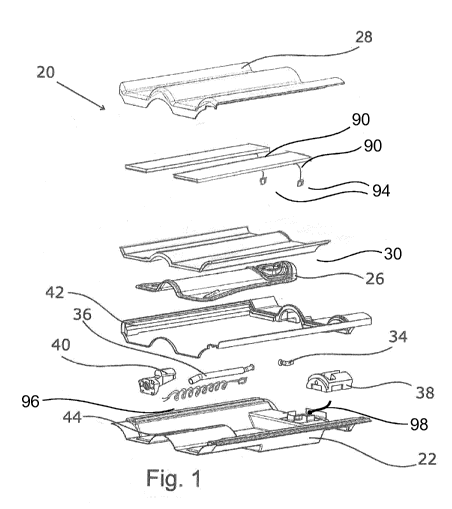
Figure 1 shows an explosive representation of a preferred embodiment of
a solar energy roof tile 20 according to the invention. Basically, the solar
energy roof tile 20 is configured in sandwich-type construction mode.
Starting from of a base tile 22, which forms a bottom side of a solar energy
roof tile 20 and is laid on top of a roof supporting structure 24 (also cf.
Figure 3), it is followed by an absorber 26 and preferably a transparent or
translucent cover 28. It is to be seen that the absorber 26 is formed of an
CA 03016722 2018-09-06
17
upper absorber element 30 and a lower absorber element 32. In the
exemplary embodiment shown, two photovoltaic modules 90 are arranged
adjacent to each other between the cover 28 and the upper absorber
element 30. The photovoltaic modules 90 abut on the upper absorber
element 30 to assure optimal heat transfer. The photovoltaic modules 90
and the upper absorber element 30 are preferably adhered to each other
with a heat conductive adhesive.
A combined element is also conceivable, which forms the upper absorber
element 30 and the photovoltaic module 90 together, preferably adjacent
to each other. The cover 28 approximately has the same shape as the upper
absorber element 30, thus entirely covering said absorber element. The
lower absorber element 32 will be passed-through by a fluid not shown. It
is therefore coupled to an inlet line 34 and an outlet line 36. The inlet line
34 is followed by a first connecting element 38 and the outlet line is
followed
by a second connecting element 40. The two connecting elements 38, 40
each may be connected to a corresponding connecting element 38, 40 of
an adjacent solar energy roof tile 20.
A frame 42 is furthermore shown, approximately having the dimensions of
the base tile 22 and serving for the accommodation of the absorber 26.
Moreover, in the working example shown, the cover 28 is supported on the
frame 42 and is connected thereto.
The second connecting element 40 is guided in a longitudinal groove 44 of
the base tile 22. This significantly facilitates assembly of the solar energy
roof tile 20 by way of specifically pulling out the second connecting element
40. The longitudinal groove 44 furthermore avoids distortion of the second
connecting element 40.
Finally, it is essential for the outlet line 36, which is arranged between the
lower absorber element 32 and the second connection element 40 to be
CA 03016722 2018-09-06
18
changeable in length. In the working example shown, it is formed as a
trumpet pipe, which is formed of two pipe portions which are slidable into
each other and having different diameters. The photovoltaic modules 90
comprise electrical cable connections 94. Moreover, a first power line 96 is
shown, which helically extends around the outlet lines 36 30 of the absorber
26 and is connected with the second connecting element 40. A second
power line 98 is connected to the first connecting element 38. The first
power line 96, the second power line 98 and the cable connections 94 are
connected to each other, preferably via a plug-in element not shown, such
that several solar energy roof tiles 20 are interconnected in a parallel
ascending manner. In an especially advantageous embodiment variant,
which is not shown herein, the first power line 96 is arranged within the
outlet line 36. It may also extend in the interior of the outlet line 36, but
the outlet line 36 may also comprise a cavity, preferably a longitudinal
channel in its wall, in which longitudinal channel the first power line 96
extends. This has the advantage, that the power line 96 cannot come in
contact with the fluid. In the embodiment variant shown, the two
connecting elements 38, 40 each have an electrical contact surface, which
in turn is electrically conductive connected to the associated power line 96,
98, wherein the contact surfaces, in the assembled state of two connecting
elements 38, 40, contact each other, thus causing the electrical connection.
From the Figures 2 to 4, the installation according to the invention of solar
energy roof tiles 20 on a roof or a roof supporting structure 24,
respectively,
becomes clear. Figure 2 shows a top view of a region of a roof Figure 3
shows a longitudinal section across a row of solar thermal roof tiles 20, and
Figure 4 shows an enlarged view of the region B from Figure 3.
It is to be seen that the solar energy roof tiles 20 which are connected to
each other, overlap in some areas, similar to conventional roofing with
conventional roof tiles. They abut against the roof supporting structure 24
with their bottom side, i.e. the bottom side of the base tile 22. Especially
CA 03016722 2018-09-06
19
in Fig. 4 it is shown that respective adjacent solar energy roof tiles 20
arranged one over the other, and are connected to each other via the
connecting elements 38, 40. Thus flow-through fluid is passed from a solar
energy roof tile 20 through the inlet line 34, the two connecting elements
.. 38, 40, the absorber 26 and the outlet lines 36, or electrical power is
passed
through the cable connections 94, the two power lines 96,98 and the
photovoltaic module 90 to the next solar energy roof tile 20, respectively.
As it is especially shown in figure 4, the solar energy roof tiles 20 are
mounted via the retaining collars 100 into the roof supporting structure 24,
the especially roof battens. The retaining collars engage behind the roof
supporting structure 24. Figure 5 illustrates the design of the solar energy
roof tile 20 according to the invention. It is to be seen that the first
connecting element 38 is followed by the inlet line 34 and leading to the
lower absorber element 32. After the fluid flows through the lower absorber
element 32 and has appropriately been heated it is passed to the second
connecting element 40 through the outlet line 36.
For installation of the solar thermal roof tiles 20 it is furthermore of
advantage, that the absorber 26, especially the upper absorber element 30
as well as the cover 28, do not entirely cover the first connection element
38 so that it easily remains accessible during tiling the roof. The first
connection element 38 will finally be first covered by the installed adjacent
solar energy roof tile 20, thereby being no longer visible in the installed
state.
Figure 6 shows a longitudinal section of a solar energy roof tile 20 having
extended second connection element 40. The outlet line 36, which, in the
working example shown, is formed as a trumpet pipe, is changeable in
length, so that the second connection element 40 may be pulled out beyond
the overall dimensions of the solar energy roof tile 20. It then protrudes
CA 03016722 2018-09-06
opposite of the respective edge or side of the solar energy roof tile 20 and
may smoothly be connected to an adjacent first connection element 38.
Figure 7 explains, by way of a top view representation of the solar energy
5 roof tile 20, that in the initial state, there are no elements protruding
over
the overall dimensions of the solar energy roof tile 20. The overall
dimensions are specified by the two transverse sides 80 and the two
longitudinal sides 82. It may as well be seen that an accommodation
opening 46 of the first connecting element 38, in the initial state, is not
10 covered by the absorber 26 or the cover 28, but is open towards the top,
i.e. towards the direction facing away from the base tile 22. The
accommodation opening 46 essentially is formed as being T-shaped.
The Figures 8 and 9 exemplify the advantageous connection of two solar
15 energy roof tiles 20 via the two connecting elements 38, 40. The two
connecting elements 38, 40 are shown in longitudinal section view, wherein
the outlet line 36 is not being drawn. What may be seen is the
accommodation opening 46 (or accommodating recess), into which the
second connecting element 40 is insertable. The T-shape causes the
20 connection to be secured in essentially horizontal direction, i.e. in
the
extension direction of the second connecting element 40, and the two
connecting elements 38, 40 may not be disengaged from each other.
In addition, spring-loaded pins 48 are to be seen as snap-in elements. In
the working example shown, two pins 48 are provided, each one of which
being oriented parallel adjacent to the outlet line 36.
A spring element 50 urges the respective pin 48 towards an accommodation
52, which is arranged in the second connecting element 40. A snap-in or
click connection will thereby result, which also secures essentially in the
vertical direction, i.e. transversally to the extension direction of the
second
connecting element 40. The pins 48 each have a conically shaped free end,
CA 03016722 2018-09-06
21
the diameter of which is dimensioned such that the pins 48 will not be
entirely inserted into the respective accommodation 52. In this way, it will
be achieved that the spring force of the spring element 50 acts towards an
appropriate edge of the respective accommodation 52, thus urging the
second connecting element 40 against an opposite opening of the inlet line
34. The openings of the outlet line 36 and the inlet line 34 therein abut
against each other. The pressure of the spring element 50 causes a tight
connection between the two connecting elements 38, 40 and the electrical
connection between the contact surfaces to be assured.
In the exemplary embodiment, an edge of the accommodation 52 and the
outer surface of the pins 48 serve as contact surfaces for the electrical
connection of the two connecting elements 38, 40.
Figure 9 furthermore shows that, in the assembled state of the two
connecting elements 38, 40, an access opening 54 for a tool 56 results.
Into this access opening 54, an angular-shaped tool 56 is insertable, by
which tool the two pins 48 may be pushed back against the spring force of
the spring element 50, thus allowing release of the two connecting
elements 38, 40 from each other.
From Figure 10 it will be seen how a system is to be designed, which makes
use of the solar energy roof tile according to the invention 20. Relatively
cold fluid is supplied to the solar energy roof tiles 20 via a cold-water line
58. Said fluid will be heated when flowing through the solar energy roof
tiles 20 connected to each other and will be recycled via a hot water line
60 back to the heat exchanger 62, or alternatively will be recycled back to
direct utilization. The two connecting lines, i.e. the cold-water line 58 and
the hot water line 60, couple the solar energy roof tiles 20 to the
utilization
facility, for example a water supply system of house. A main power line 92
extends parallel to the cold-water line 58 and the hot water line 60 (cf.
CA 03016722 2018-09-06
22
figure 13). The main power line 92 may sectionally be arranged in the
region of a gutter board of the roof.
Figure 11 illustrates the conveyance of the relatively cold fluid via a
feeding
line 64 to the solar energy roof tiles 20. The feeding line 64 preferably is
arranged in the region of a gutter board of the roof. A row of solar energy
roof tiles 20, which are arranged in the edge region of an area of solar
energy roof tiles 20 according to the invention, preferably the lower row of
a roof, is coupled to feeding line 64 via a supply feeding line 66. The supply
feeding line 66 connects the feeding line 64 to each of the first connection
element 38 of a solar energy roof tile 20.
Figure 12 shows attachment of the solar energy roof tiles 20 of the
uppermost row to a collecting line 68. A collecting supply line 70 extends
from the second connection element 38 into the collecting line 68, feeding
heated fluid thereto.
Figure 13 illustrates an advantageous installation of the connecting lines,
i.e. the cold-water line 58 and the hot water line 60 as well as the main
power line 92, in some places within a downspout 72. In this case, the
downspout 72 preferably is divided into two compartments by a separating
wall 74, wherein a first compartment 76 is for discharging rain water, a
second compartment 78 is for accommodating the two connecting lines 58,
60 and the main power line 92. This mode of installation, on the one hand,
is cost-effective and quickly feasible, on the other hand the external
appearance of the house will not negatively be effected.
The Figures 14 and 15 show an alternative mode of connecting by means
of a rotary slide 102 in a schematic diagram. The rotary slide 102 replaces
the retaining collars 100 and, accordingly, is arranged approximately in that
region. The solar energy roof tiles according to invention 20 are engaged
into the roof supporting structure 24 via the rotary slide 102.
CA 03016722 2018-09-06
23
The rotary slide 102 has a free space 104, via which the roof supporting
structure 24 may be released as it is, so that the solar energy roof tile 20
is displaceable in an axial direction. For pulling out or inserting the solar
energy roof tile 20, the rotary slide 102 is required to be turned into the
appropriate position, so that it no longer engages behind the roof
supporting structure 24. For this, the rotary slide 102 comprises a rotational
axis 106 (cf. figure 15).
The rotary slide 102 simultaneously is the abutment for the second
connecting element 40, which otherwise could be further displaced into the
axial direction. This especially arises from figure 16. The second connecting
element 40 is guided in an accommodation 108 and has a step design, with
a lower base body 110 and an upper base body 112, wherein the lower
base body 110 in transversal direction to the longitudinal axis of the solar
energy roof tile 20 is formed broader than the upper base body 112.
The accommodation 108 comprises a through opening 114, through which
the upper base body 112 may axially be passed due to its lower width,
whereas the lower base body 110 may not be passed through. Moreover,
an undercut 116 is provided in the range of the through opening 114,
against which the lower base body 110 abuts from the bottom, and thus
may not be guided out of the accommodation 108 and to the top.
Figure 16 shows another advantageous embodiment variant, where
adjacent to the rotary slide 102, a sledge 122 is additionally provided,
which facilitates and secures the connection. The sledge 122 is spring-
loaded and biased at its base position via a compression spring 118. A lever
120 maintains the sledge 116 in its biased position by contacting an
abutment. If the second connecting element 40 is inserted into the first
connecting element 38 from the top, the lever 120 is pushed downwards
and becomes disengaged from the abutment, thus releasing the spring
CA 03016722 2018-09-06
24
force. The sledge 116 moves towards the rotary slide 102 to contact it.
Meanwhile, it is located below the two undercuts 116 with its lower base
body 110. Thus, the second connecting element 40 is maintained both in
the axial direction by the rotary slide 102, and in the vertical direction by
the undercut 116. Advancing the sledge 122 also causes a line portion 126,
which is part of the inlet line 34, to be pushed into the outlet line 36 of
the
second connecting element 40. Moreover, electrical contacts are closed to
transfer the electrical energy (not shown).
Furthermore, figure 15 shows a lock bolt 124, via which the solar energy
roof tile 20 is attachable to the roof supporting structure 24, for example
as a wind suction protection.
The invention is not limited to the working examples shown and
represented, but also includes other possible embodiments. Especially,
instead of the outlet line 36, the inlet line 34 or even both lines 34, 36 may
be formed as being changeable in length. Instead of the base tile 22, it is
also conceivable that the absorber 26 is for mounting directly to the roof
structure 24, i.e. the base tile 22 may thus be omitted.