Language selection

Search

Patent 3017226 Summary

Third-party information liability

Some of the information on this Web page has been provided by external sources. The Government of Canada is not responsible for the accuracy, reliability or currency of the information supplied by external sources. Users wishing to rely upon this information should consult directly with the source of the information. Content provided by external sources is not subject to official languages, privacy and accessibility requirements.

Claims and Abstract availability

Any discrepancies in the text and image of the Claims and Abstract are due to differing posting times. Text of the Claims and Abstract are posted:

  • At the time the application is open to public inspection;
  • At the time of issue of the patent (grant).
(12) Patent Application: (11) CA 3017226
(54) English Title: SYSTEM FOR COVERING FLAT SURFACES
(54) French Title: SYSTEME DE REVETEMENT DE SURFACES PLATES
Status: Report sent
Bibliographic Data
(51) International Patent Classification (IPC):
  • A01G 13/02 (2006.01)
(72) Inventors :
  • REBOLDI, ALESSANDRO (Italy)
  • ANGOLI, ROBERTO (Italy)
(73) Owners :
  • REM TEC S.R.L. (Italy)
(71) Applicants :
  • REM TEC S.R.L. (Italy)
(74) Agent: OYEN WIGGS GREEN & MUTALA LLP
(74) Associate agent:
(45) Issued:
(86) PCT Filing Date: 2016-05-23
(87) Open to Public Inspection: 2017-11-30
Examination requested: 2021-05-04
Availability of licence: N/A
(25) Language of filing: English

Patent Cooperation Treaty (PCT): Yes
(86) PCT Filing Number: PCT/IT2016/000134
(87) International Publication Number: WO2017/203545
(85) National Entry: 2018-09-06

(30) Application Priority Data: None

Abstracts

English Abstract

System for covering flat surfaces that is installed on support structures formed by support poles (2) maintained in position by a network of tie-rods (3), both the support poles and the tie-rods being fixed on the surface by means of suitable pins. Said system comprises a plurality of pairs of elongated support elements (6,6') having a lower portion positioned on such poles (2) and being joined together in raised position in proximity to their upper end, to form a plurality of pairs of slopes on which protection nets or protection sheets (7) are positioned, which in open position cover the area below the support structure and which in closed position are compact and amassed between adjacent poles (2) of the same row; the movement from the open position to the closed one and vice versa being obtained through the sliding of the sheet along the support elements by means of movement means.


French Abstract

L'invention concerne un système de revêtement de surfaces plates qui est installé sur des structures de support formées par des montants de support (2) maintenus en position par un réseau de tirants (3), les montants de support et les tirants étant fixés sur la surface au moyen de broches appropriées. Ledit système comprend une pluralité de paires d'éléments de support allongés (6, 6') ayant une partie inférieure positionnée sur lesdits montants (2) et reliés ensemble en position relevée à proximité de leur extrémité supérieure, pour former une pluralité de paires de pentes sur lesquelles des feuilles de protection ou des filets de protection (7) sont positionnés, qui, en position ouverte, recouvrent la zone en dessous de la structure de support et qui, en position fermée, sont compacts et rassemblés entre des montants adjacents (2) de la même rangée ; le déplacement de la position ouverte à la position fermée, et inversement, étant obtenu par coulissement de la feuille le long des éléments de support à l'aide de moyens de déplacement.

Claims

Note: Claims are shown in the official language in which they were submitted.


1

CLAIMS

1. System for covering flat surfaces that can be
installed on support structures formed by support poles
(2) maintained in position by a network of tie-rods
(3), both the support poles and the tie-rods being
fixed on the surface by means of suitable pins,
said system comprising a plurality of pairs of
elongated support elements (6,6') having a lower
portion positioned on such poles (2) and being joined
together in raised position in proximity to their upper
end, to form a plurality of pairs of slopes on which
protection nets or protection sheets (7) can be
positioned, which in open position cover the area below
the support structure and which in closed position are
compact and amassed between adjacent poles (2) of the
same row; the movement from the open position to the
closed one and vice versa being obtained through the
sliding of the sheet along the support elements by
means of movement means, wherein on the top of such
structures above said sheets electrical energy
generation units can be installed.
2. System according to claim 1, wherein the joining
point and of maximum height or top (61) of each pair of
elements, is positioned on such tie-rods (3).
3. System according to claim 1, wherein such elongated
elements are constrained to the poles at a
substantially intermediate height with respect to the
height of the pole itself.
4. System according to claim 1, wherein such elongated
elements are metal cables or metal bars, or section
bars.


2

5. System according to claim 1, wherein the sheets (7)
are associated with the elongated element (6,6') by
means of a plurality of constraining means (8) slidable
along such elongated element.
6. System according to claim 5, wherein such
constraining means comprise a sleeve made of two
annular sectors (81,82) provided with notches on the
edge, that when such sectors are joined together form a
groove (83) which is crimped on the edge of the sheet,
a through hole (84) of the sleeve allows the sliding on
the elongated element.
7. System according to claim 1, wherein such means for
moving the sheets comprise an annular belt (10)
arranged substantially in a position adjacent to the
elongated elements (6,6'), which substantially follows
the length thereof, moved by means of a drive pulley
(11) associated with the poles and driven by a driven
pulley (12) positioned at the top (61) of the
structure, the belt then being arranged along the
entire path of the slidable constraining means (8),
which are also constrained to such belt by means of a
bracket (85).
8. System according to claim 7, wherein each drive
pulley is rotated by means of an electric motor (13),
or it can be manually moved by means of a rod (14).
9. System according to claim 1, wherein the elongated
elements are fixed to the poles and to the tie-rods by
means of fixing means which comprise:
.cndot. a ring (9) crimped on the pole provided with
eyelets (91), to which the end of the elongated
element (6.6') is fixed when this is an
intermediate pole of the structure,


3

.cndot. a bush (9') which crosses the pole as well as the
support element which is then fixed to the ground,
if the pole is the final pole of the structure,
.cndot. a support (9") crimped on the tie-rod (3) which in
its lower portion has fixing eyelets (91') for the
elongated element.
10. System according to claim 7 and 9, wherein the
driven pulley (13) is associated with the top support
(9") of the structure.
11. System according to claim 1, wherein such nets or
sheets are shade nets or sheets used in agriculture.
12. System according to claim 11, wherein such nets are
made of polyethylene stabilized against UV rays, with a
shading degree of 50-90%.
13. System according to claim 1, wherein such sheets
are anti-hail sheets.
14. System according to claim 1, wherein such sheets
are transparent sheets.
15. System according to claim 1, in which said
electrical energy generation units are photovoltaic
panels or wind units directly placed on the top of the
support poles.

Description

Note: Descriptions are shown in the official language in which they were submitted.


CA 030=6 20109-06
WO 2017/203545 PCT/IT2016/000134
1
SYSTEM FOR. COVERING FLAT SURFACES
The present invention refers to a support structure on
which a system is installed that is adapted to allow an
adjustable covering on flat surfaces.
Such covering can be a covering adapted to create a
shading for protecting from the solar rays or a
covering adapted to create different temperature
conditions, such as greenhouses, or a covering adapted
to protect against weather events such as hail. The
surfaces to be protected or covered are in fact,
according to a preferred embodiment, farm fields. In
particular, such structure is obtained by means of a
group of poles distributed along the farm field itself.
Structures are known that are composed of poles
positionable on farm fields, such poles supporting
electrical energy generation units, e.g. photovoltaic
panels or wind units placed on the top of such
structures.
In the patent W02010103378, a load-bearing structure is
described formed by support poles maintained in
position by a network of tie-rods, both the support
poles and the tie-rods being fixed in the ground by
means of pins. The positionable solar panels are of so-
called "solar followers" type, capable of rotating
around two axes. Such followers comprise a main
horizontal load-bearing tube, which can rotate around
its axis, to which a plurality of secondary tubes are
connected, perpendicularly fixed to the main tube and
which can be rotated around the axis thereof. The solar
panels are fixed on such secondary tubes. The ends of

CA 030=6 20109-06
WO 2017/203545 PCT/IT2016/000134
2
the main tube of the follower are abutted against and
fixed on such support poles.
In the patent W02013076573, a support pole structure is
described, of the type that also supports wind modules.
Such structure is two-dimensional in a "chessboard"
manner and can be installed on farmlands as well, since
it is raised and the distance between the support poles
is such to allow the passage of farm vehicles, even
large ones.
The Applicant has perceived that the solar illumination
of the space between the support poles can be
advantageously modulated by means of movable canvases
or curtains, anchored to such poles and/or tie-rods by
means of mechanisms and guides which also allow the
movement thereof.
The object of the present invention is to provide a
structure for shading farm fields or similar
substantially flat surfaces having the features of the
appended claim 1.
The features and advantages of the present invention
will be more evident from the following description of
an exemplary and non-limiting embodiment of the
invention, referred to the appended schematic drawings,
in which:
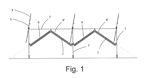
0 figure 1 illustrates, in side view, the support
structure with the shading system according to the
present invention installed;
O figure 2 illustrates, in perspective view, the
support structure with the shading system
according to the present invention installed;
O figure 3 illustrates a portion of the structure of
figures 1 and 2;

CA 0=226 2018-09-06
WO 2017/203545 PCT/IT2016/000134
3
* figure 4a illustrates in particular the means for
fixing the system to the tie-rods on the top of
the support structure;
* figure 4b illustrates in particular the means for
fixing the system to a final pole of the support
structure and the means for moving the sheet
associated with such pole;
= figure 4c illustrates in particular the means for
fixing the system to an intermediate pole of the
support structure and the means for moving the
opposite sheets associated with such pole;
= figure 5 illustrates the slidable constraining
means for the sheets with respect to the elongated
support element;
= figure 6 illustrates in particular the means for
fixing and those for moving the sheets of the
system to a pole of the support structure;
O figure 7 illustrates a means for the slidable
constraining of the sheets like that illustrated
in figure 5;
= figure 8 illustrates a manual means for moving the
sheets, associated with a pole.
With reference to the abovementioned figures, the
covering system according to the present invention is
installed on support structures formed by support poles
2 maintained in position by a network of tie-rods 3,
both the support poles and the tie-rods are fixed in
the ground by means of suitable pins. Such structure is
configured two-dimensional, e.g. following a
"chessboard" scheme and can also be installed on
farmlands, since it is raised and the distance between

CA 030=6 20109-06
WO 2017/203545 PCT/IT2016/000134
4
the support poles is such to allow the passage of farm
vehicles, even large ones.
On such structures, electrical energy generation units
can be installed or positioned, for example
photovoltaic panels or wind units, placed on the top of
such structures. Such units can be directly placed on
the top of the support poles, or they can be positioned
horizontally between one pole and the other.
In the illustrated example, solar followers are placed
on the structure, that comprise a main horizontal load-
bearing tube 4, which can rotate around its axis, to
which a plurality of secondary tubes 5 are connected,
which are perpendicularly fixed to the main tube and
which can be rotated around the axis thereof. The solar
panels P can be fixed on such secondary tubes.
The covering system comprises a plurality of pairs of
elongated support elements 6 and 6' having a lower
portion positioned on such poles 2 and being joined
together in raised position in proximity to their upper
end, to form a plurality of pairs of slopes on which
protection nets or protection sheets 7 can be
positioned, which in open position cover the area below
the support structure and which in closed position are
compact and amassed between adjacent poles 2 of the
same row; the movement from the open position to the
closed position and vice versa occurs through sliding
of the sheet along the support elements.
In general, the nets that can be coupled to the system
of the present invention can be of different type, in
accordance with the requirements of the farm
cultivation below the plant.

CA 030=6 20109-06
WO 2017/203545 PCT/IT2016/000134
Generally, the system is designed for shade nets used
in agriculture. In substance, these are nets made of
polyethylene stabilized against UV rays, with a
different shading degree (50%,7096,9096 depending on the
5 requirements). In place of the shade nets, however,
also anti-hail nets can be installed, or transparent
sheets if one wishes to make a greenhouse (in this
case, lateral vertical closures would also have to be
provided).
The joining point and of maximum height or top 61 of
each pair of elements, is advantageously positioned on
such tie-rods 3. In addition, such elongated elements
are advantageously constrained to the poles at a
substantially intermediate height with respect to the
height of the pole itself.
Such elongated elements in the illustrated embodiment
are metal cables or metal bars, but in an equivalent
manner they could be substituted by section bars.
The sheets are associated with the elongated element 6
or 6' by means of a plurality of constraining means 8
slidable along such elongated element. In the
illustrated embodiment, such constraining means
comprise a sleeve made of two annular sectors 81 and 82
provided with notches on the edge, that when such
sectors are joined together, for example by means of
screws, they form a groove 83 which is crimped on the
edge of the sheet. A through hole 84 of the sleeve
allows the sliding on the elongated element.
Clearly, such solution could be achieved with
equivalent means, e.g. with an elongated section bar in
place of the cable 6 or 6' provided with dovetail

CA 030=6 20109-06
WO 2017/203545 PCT/IT2016/000134
6
guides in which the slidable constraining means to the
sheet are engaged.
Such slidable constraining means also comprise a
bracket 85 associated with the sleeve, which is moved
together with the sleeve along the elongated element by
the means for moving the sheets associated with such
poles.
The elongated elements are fixed to the poles and to
the tie-rods by means of fixing means which comprise a
ring 9 crimped on the pole provided with eyelets 91, to
which the end of the elongated element 6 or 6' is fixed
when this is an intermediate pole of the structure. If
the pole is the final pole of the structure, such
fixing means comprise a bush 9' which crosses the pole
as well as the support element which is then fixed to
the ground. Such fixing means also comprise a support
9" crimped on the tie-rod 3 which in its lower portion
has fixing eyelets 91" for the elongated element 6 or
6'.
The means for moving the sheets which allow the opening
and closing thereof substantially comprise, for at
least one side of the sheet, an annular belt 10
arranged substantially in a position adjacent to the
elongated elements 6 or 6', which substantially follows
the length thereof, moved by means of a drive pulley 11
associated with the poles and driven by a driven pulley
12 positioned at the top 61 of the structure,
advantageously at the support 9". The belt is then
arranged along the entire path of the slidable
constraining means 8, which are constrained to the
sheet and also to such belt by means of the
abovementioned bracket 85.

CA 03017226 2018-09-06
WO 2017/203545 PCT/IT2016/000134
,
7
Each drive pulley can be rotated by means of an
electric motor 13, preferably provided with reduction
mechanism, or it can be manually moved by means of a
rod 14. The driven pulley 13 is advantageously
associated with the top support 9" of the structure.

Representative Drawing
A single figure which represents the drawing illustrating the invention.
Administrative Status

For a clearer understanding of the status of the application/patent presented on this page, the site Disclaimer , as well as the definitions for Patent , Administrative Status , Maintenance Fee  and Payment History  should be consulted.

Administrative Status

Title Date
Forecasted Issue Date Unavailable
(86) PCT Filing Date 2016-05-23
(87) PCT Publication Date 2017-11-30
(85) National Entry 2018-09-06
Examination Requested 2021-05-04

Abandonment History

Abandonment Date Reason Reinstatement Date
2023-09-11 R86(2) - Failure to Respond

Maintenance Fee

Last Payment of $210.51 was received on 2023-05-08


 Upcoming maintenance fee amounts

Description Date Amount
Next Payment if small entity fee 2024-05-23 $100.00
Next Payment if standard fee 2024-05-23 $277.00

Note : If the full payment has not been received on or before the date indicated, a further fee may be required which may be one of the following

  • the reinstatement fee;
  • the late payment fee; or
  • additional fee to reverse deemed expiry.

Patent fees are adjusted on the 1st of January every year. The amounts above are the current amounts if received by December 31 of the current year.
Please refer to the CIPO Patent Fees web page to see all current fee amounts.

Payment History

Fee Type Anniversary Year Due Date Amount Paid Paid Date
Application Fee $400.00 2018-09-06
Maintenance Fee - Application - New Act 2 2018-05-23 $100.00 2018-09-06
Maintenance Fee - Application - New Act 3 2019-05-23 $100.00 2019-04-23
Maintenance Fee - Application - New Act 4 2020-05-25 $100.00 2020-04-08
Request for Examination 2021-05-25 $816.00 2021-05-04
Maintenance Fee - Application - New Act 5 2021-05-25 $204.00 2021-05-12
Maintenance Fee - Application - New Act 6 2022-05-24 $203.59 2022-05-11
Maintenance Fee - Application - New Act 7 2023-05-23 $210.51 2023-05-08
Owners on Record

Note: Records showing the ownership history in alphabetical order.

Current Owners on Record
REM TEC S.R.L.
Past Owners on Record
None
Past Owners that do not appear in the "Owners on Record" listing will appear in other documentation within the application.
Documents

To view selected files, please enter reCAPTCHA code :


To view images, click a link in the Document Description column. To download the documents, select one or more checkboxes in the first column and then click the "Download Selected in PDF format (Zip Archive)" or the "Download Selected as Single PDF" button.

List of published and non-published patent-specific documents on the CPD .

If you have any difficulty accessing content, you can call the Client Service Centre at 1-866-997-1936 or send them an e-mail at CIPO Client Service Centre.


Document
Description 
Date
(yyyy-mm-dd) 
Number of pages   Size of Image (KB) 
Examiner Requisition 2022-08-31 5 244
Request for Examination 2021-05-04 4 101
Amendment 2022-12-30 21 692
Drawings 2022-12-30 4 192
Claims 2022-12-30 3 159
Description 2022-12-30 7 424
Examiner Requisition 2023-05-10 5 243
Abstract 2018-09-06 1 102
Claims 2018-09-06 3 113
Drawings 2018-09-06 4 2,788
Description 2018-09-06 7 368
Representative Drawing 2018-09-06 1 83
National Entry Request 2018-09-06 4 116
Assignment 2018-09-10 3 132
International Preliminary Report Received 2018-09-07 13 616
International Search Report 2018-09-06 2 51
Representative Drawing 2018-09-19 1 21
Cover Page 2018-09-19 1 55