Note: Descriptions are shown in the official language in which they were submitted.
SIDE UNDERRIDE GUARD
CROSS REFERENCE TO RELATED APPLICATIONS
[0001] This application claims the benefit of U.S. Provisional
Application Serial No.
62/557,977 filed on September 13, 2017, and entitled "Side Underride Guard,"
the disclosure of
which is incorporated herein by reference in its entirety.
FIELD OF THE INVENTION
[0002] The present invention relates generally to semi-trailers, such as
van-type trailers,
for example. In particular, the present invention relates to both an
aerodynamic side skirt system
for reducing drag on such a trailer as well as a side underride system for
preventing or reducing
the extent to which an automobile may ride under the trailer in the event of a
side impact collision,
for example.
BACKGROUND
[0003] To reduce wind flow resistance and drag on a trailer, truck, semi-
trailer, or other
vehicle, side skirts that extend downwardly from a bottom of the trailer
and/or chassis toward the
roadway to partially enclose the floor assembly and undercarriage have been
utilized.
[0004] Air flow passing under a ground vehicle imparts a drag force to
the vehicle when it
impinges on and flows around the vehicle undercarriage components attached to
or a part of the
underside of a vehicle. Side skirt systems are designed to prevent or control
the flow of air from
entering the undercarriage region from a side of the ground vehicle, such as a
trailer of a tractor-
trailer truck system, for example. Such reduction on the drag of the ground
vehicle may operate to
conserve fossil fuels as well as other sources of vehicle drive power for
hybrid vehicles, battery-
operated vehicles, and/or alternative fuel-based vehicles, for example.
CA 3017256 2018-09-13
WNC -2017-24
156100.00942
100051 Trailers typically have a higher elevation than passenger
vehicles. This presents a
risk that a passenger vehicle may underride the trailer in an accident,
potentially resulting in
damage to the underriding vehicle and injury to occupants therein.
Accordingly, a side protection
device, or underride guard, may be provided for use with a trailer in order to
reduce the risk of
such passenger vehicles underriding the trailer. Side protection devices are
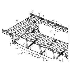
intended to reduce the
extent to which a "passenger vehicle" (as defined in 49 C.F.R. Part 571) can
intrude under the side
of a trailer, diminishing passenger compartment intrusion.
SUMMARY
[00061 The present disclosure may comprise one or more of the following
features and
combinations thereof
[0007] According to one embodiment of the disclosure, a side underride
system configured
to be coupled to a trailer is provided. The side underride system includes a
support system,
including a brace system and a cable, configured to be positioned below the
trailer to provide side
underride protection. The brace system includes a plurality of cross-braces
that each extend across
a width of the trailer and are spaced apart at intervals along a length of the
trailer. The cable is
configured to extend across the intervals between the cross-braces.
[0008] According to another embodiment, a side underride system underride
system
configured to be coupled to a trailer is provided. The side underride system
includes a brace system
with a plurality of cross-braces. Each cross-brace of the plurality of cross-
braces comprises a first
vertical post, a second vertical post opposite the first vertical post, a
first truss beam oriented
diagonally and coupled to a lower portion of the first vertical post and an
upper portion of the
second vertical post, and a second truss beam oriented diagonally and coupled
to an upper portion
of the first vertical post and a lower portion of the second vertical post so
that the first truss beam
2
CA 3017256 2018-09-13
WNC-2017-24
156100.00942
and the second truss beam crisscross at an intersection point. Each cross-
brace of the plurality of
cross-braces extends across a width of the trailer and is configured to be
coupled to the trailer as a
subassembly unit so that the plurality of cross-braces are spaced apart from
one another at intervals
along a length of the trailer.
[0009] Accordingly to yet another embodiment, a method of installing a
side underride
system on a trailer is provided. The method includes welding a first bracket
to a first cross member
of a floor assembly of the trailer adjacent a first end of the first cross
member and welding a second
bracket to the first cross member adjacent a second end of the first cross
member. The method also
includes providing a first cross-brace comprising a first vertical post, a
second vertical post
opposite the first vertical post, a first truss beam oriented diagonally and
coupled to a lower portion
of the first vertical post and an upper portion of the second vertical post,
and a second truss beam
oriented diagonally and coupled to an upper portion of the first vertical post
and a lower portion
of the second vertical post so that the first truss beam and the second truss
beam crisscross at an
intersection point. The method further includes coupling the first vertical
post to the first bracket
and coupling the second vertical post to the second bracket.
[0010] These and other features of the present disclosure will become
more apparent from
the following description of the illustrative embodiments.
BRIEF DESCRIPTION OF THE DRAWINGS
[0011] FIG. 1 is a perspective view of a trailer and an aerodynamic side
skirt system
coupled to the trailer between rear wheels and a landing gear, or front
support, of the trailer, with
a portions of trailer removed therefrom for clarity.
[0012] FIG. 2 is a side view of a side underride system including an
aerodynamic side skirt
system and a support system between portions of the side skirt system.
3
CA 3017256 2018-09-13
WNC-2017-24
156100.00942
[0013] FIG. 3 is a side view of the side underride system of FIG. 2 with
the side skirt
system removed for clarity.
[0014] FIG. 4 is a partial perspective, front, underside view of the side
underride system
of FIG. 2.
[0015] FIG. 5 is a perspective front, topside view of the side underride
system of FIG. 2
with the side skirt system removed for clarity.
[0016] FIG. 6 is a perspective rear, underside view of the side underride
system of FIG. 2
with the side skirt system removed for clarity.
[0017] FIG. 7 is a bottom elevational view of the side underride system of
FIG. 2 with the
side skirt system removed for clarity.
[0018] FIG. 8 is a perspective view of a cross-brace for use with the
support system of the
side underride system of FIG. 2.
[0019] FIG. 8A is an enlarged perspective view of a portion of the cross-
brace of FIG. 8,
showing a bracket for use with the support system of the side underride system
of FIG. 2.
[0020] FIG. 9 is a perspective view of another cross-brace for use with
the support system
of the side underride system of FIG. 2.
[0021] FIG. 10 is a partial perspective view of a truss beam for use with
a cross-brace of
the support system of the side underride system of FIG. 2.
[0022] FIG. 11 is a perspective view of another cross-brace for use with
the support system
of the side underride system of FIG. 2.
[0023] FIG. 12 is a partial perspective, rear view of the side underride
system of FIG. 2,
including the cross-brace of FIG. 11.
[0024] FIG. 13 is a partial perspective rear, topside view of the side
underride system of
4
CA 3017256 2018-09-13
WNC-2017-24
156100.00942
FIG. 2 with the side skirt system removed for clarity.
[0025] FIGS. 14 and 14A are a partial perspective view and a partial side
view,
respectively, of a vertical post and a cable for use with a support system of
a side underride system.
[0026] FIG. 15 is partial perspective view of another vertical post and a
cable for use with
a support system of a side underride system.
[0027] FIG. 16 is a perspective front, underside view of the side
underride system of FIG.
2 with the side skirt system removed for clarity.
[0028] FIG. 17 is a perspective front, topside view of an anchor point
for a cable system
of the side underride system of FIG. 2.
[0029] FIG. 18 is a partial side view of the anchor point of FIG. 17.
[0030] FIG. 18A is partial perspective front, topside view of the anchor
point of FIG. 18.
[0031] FIG. 19 is a partial perspective, rear, underside view of another
anchor point for a
cable system of the side underride system of FIG. 2.
[0032] FIG. 19A is another partial perspective underside view of the
anchor point of FIG.
19.
[0033] FIG. 20 is a partial perspective topside view of a side underride
system including
an aerodynamic side skirt system and a support system having cross-braces
connected by a rigid
member.
[0034] FIG. 21 is another partial perspective topside view of the side
underride system of
FIG. 20.
[0035] FIG. 22 is a partial perspective view of a vertical post and a
rigid member for use
with a support system of a side underride system.
DETAILED DESCRIPTION
CA 3017256 2018-09-13
WNC-2017-24
156100.00942
[0036] Before any embodiments of the invention are explained in detail,
it is to be
understood that the invention is not limited in its application to the details
of construction and the
arrangement of components set forth in the following description or
illustrated in the following
drawings. The invention is capable of other embodiments and of being practiced
or of being carried
out in various ways. Also, it is to be understood that the phraseology and
terminology used herein
is for the purpose of description and should not be regarded as limiting. The
use of "including,"
"comprising," or "having" and variations thereof herein is meant to encompass
the items listed
thereafter and equivalents thereof as well as additional items. Unless
specified or limited
otherwise, the terms "mounted," "connected," "supported," and "coupled" and
variations thereof
are used broadly and encompass both direct and indirect mountings,
connections, supports, and
couplings. Further, "connected" and "coupled" are not restricted to physical
or mechanical
connections or couplings.
[0037] The following discussion is presented to enable a person skilled
in the art to make
and use embodiments of the invention. Various modifications to the illustrated
embodiments will
be readily apparent to those skilled in the art, and the generic principles
herein can be applied to
other embodiments and applications without departing from embodiments of the
invention. Thus,
embodiments of the invention are not intended to be limited to embodiments
shown, but are to be
accorded the widest scope consistent with the principles and features
disclosed herein. The
following detailed description is to be read with reference to the figures, in
which like elements in
different figures have like reference numerals. The figures, which are not
necessarily to scale,
depict selected embodiments and are not intended to limit the scope of
embodiments of the
invention. Skilled artisans will recognize the examples provided herein have
many useful
alternatives and fall within the scope of embodiments of the invention.
6
CA 3017256 2018-09-13
WNC -2017-24
156100.00942
[0038] As used herein, unless otherwise specified or limited, "at least
one of A, B, and C,"
and similar other phrases, are meant to indicate A, or B, or C, or any
combination of A, B, and/or
C. As such, this phrase, and similar other phrases can include single or
multiple instances of A, B,
and/or C, and, in the case that any of A, B, and/or C indicates a category of
elements, single or
multiple instances of any of the elements of the categories A, B, and/or C.
[0039] For the purposes of promoting an understanding of the principles
of the invention,
reference will now be made to a number of illustrative embodiments shown in
the attached
drawings and specific language will be used to describe the same. While the
concepts of this
disclosure are described in relation to a box-type trailer, it will be
understood that they are equally
applicable to many types of trailers, semi-trailers, and tanks generally, and
more specifically to
conventional flat-bed trailers, box or van type trailers, and/or pup trailers,
as well as straight truck
bodies, small personal and/or commercial trailers and the like. Furthermore,
while the concepts of
this disclosure may be described in relation to a box-type trailers, it will
be understood that that
they are equally applicable to other trailers generally and any type of over-
the-road storage
container. Accordingly, those skilled in the art will appreciate that the
present invention may be
implemented in a number of different applications and embodiments and is not
specifically limited
in its application to the particular embodiments depicted herein.
[0040] Generally, some embodiments of the disclosure provide an
integrated system of an
aerodynamic side skirt and side underride protection in one common system. The
system
incorporates both an aerodynamic side skirt for reducing air drag on a trailer
and a side underride
guard for preventing or reducing the extent to which a vehicle may ride under
the trailer, as well
as preventing or reducing the extent to which a trailer body may intrude into
the passenger
compartment of the vehicle. In some embodiments, there is no clear division
between the skirt and
7
CA 3017256 2018-09-13
WNC-2017-24
156100.00942
the guard; in other embodiments, the side underride guard may be retrofit with
existing skirt
systems; in yet other embodiments, the side underride guard may be a
standalone system without
a skirt. Generally, the systems described herein can help generate a
retardation or restriction force
to decelerate an impacting vehicle and absorb the vehicle's kinetic energy to
prevent or reduce
passenger compartment intrusion (PCI).
100411 FIG. 1 depicts a trailer 10 including an aerodynamic skirt system
or assembly 12
coupled to and extending downwardly from each side wall 14 of the trailer 10.
Illustratively, the
skirt system 12 operates to improve the aerodynamic efficiency of the trailer
10 by reducing drag
and wind flow under the trailer 10. In particular, the skirt system 12
operates to reduce airflow
under the trailer 10 while the trailer 10 is traveling down a road (e.g.,
being towed by a tractor, as
a tractor/trailer combination). Reduction of airflow under the trailer 10 may
increase the fuel
efficiency, or the efficiency of any other such source of vehicle drive power,
of the tractor/trailer
combination. Illustratively, the skirt system 12, as well as other skirt
systems described herein,
extends below a side wall 14 of the trailer 10 at least partially along a
length of the trailer. In
particular, in some embodiments, the skirt system 12 extends generally between
a landing gear 24
and a rear wheel assembly 22 of the trailer 10. However, the skirt systems
described herein may
be modified to extend along a greater or a lesser length of the trailer 10
than what is illustratively
shown in the figures. In other words, the skirt systems disclosed herein may
be modified to extend
along the entire, or substantially the entire, length of the trailer 10 or may
be modified to extend
along only a small portion of the length of the trailer 10. Further, any of
the skirt systems disclosed
herein may be for structural and/or aerodynamic purposes.
100421 As shown in FIG. 1, the trailer 10 includes side walls 14, a front
end wall 16, a rear
end wall 18, and a roof 20 defining an inside storage portion (not shown) able
to store various
8
CA 3017256 2018-09-13
WNC-2017-24
156100.00942
articles or goods therein. The trailer 10 further includes the rear wheel
assembly 22 and the front
support or landing gear 24 each coupled to a bottom wall or floor assembly 26
of the trailer 10.
Illustratively, the floor assembly 26 of the trailer 10 includes various
laterally-extending cross
members 40 and right and left base rails 28 coupled to the cross members 40
and extending along
a length of the trailer 10. In some embodiments, the front end of the trailer
10 is configured to be
coupled to a tractor (not shown) for towing the trailer 10 thereon, thus
providing a tractor-trailer
assembly. In other embodiments, a cab is integral with the storage
compartment, for example, in
refrigerated and dry truck bodies. Illustratively, while the specific trailer
10 is shown and described
herein, other trailers including other components, such as composite floor
assemblies, for example,
which may or may not include any cross members 40 are contemplated as well.
[0043] As shown in FIG. 1, the skirt system 12 is coupled to the floor
assembly 26 of the
trailer 10 and extends downwardly from the base rail 28 of the trailer 10.
Illustratively, the side
skirt system 12 is positioned between the rear wheel assembly 22 and the front
support 24 in order
to prevent air from flowing laterally under the floor assembly 26 of the
trailer 10 as the trailer 10
is towed by a tractor. It should be understood that while the aerodynamic side
skirt system 12 is
shown for use with a trailer 10, the side skirt system 12 and/or side
underride guards disclosed
herein may be coupled to any vehicle to reduce the drag thereon. Still
further, while the
embodiments disclosed herein are shown as being utilized with trailers, any of
the embodiments
disclosed herein may be coupled to any vehicle.
[0044] It should be noted that the trailer 10 of FIG. 1 includes two
aerodynamic skirt
systems 12. In particular, one system 12 is coupled to one side of the floor
assembly 26 of the
trailer 10 to extend downwardly from the floor assembly 26 generally parallel
to the corresponding
side wall 14 of the trailer 10, while the other system 12 is coupled to the
other side of the floor
9
CA 3017256 2018-09-13
WNC-2017-24
156100.00942
assembly 26 to extend downwardly from the floor assembly 26 generally parallel
to the
corresponding side wall 14 of the trailer 10. In other words, a first skirt
system 12 is configured to
be positioned below the trailer 10 near a first side wall 14, and a second
skirt system 12 is
configured to be positioned below the trailer 10 near a second side wall 14.
For purposes of the
description herein, only one skirt system 12 will be described. However, it
should be understood
that the two skirt systems 12 of the trailer 10 are substantially identical or
identical in configuration
and function. Also, while the skirt systems 12 are shown as being parallel to
the corresponding
side walls 14, the skirt systems 12 may be angled or curved inwardly or
outwardly relative to the
side walls 14 at forward (toward the tractor) ends thereof, as further
described below. In yet other
embodiments, any suitable skirt system may be utilized.
[0045] Generally, the skirt system 12 may include a side skirt wall 30
having one or more
wall panels 32. For example, as shown in FIG. 1, the side skirt wall 30 may
include three wall
panels 32 coupled to each other. The wall panels 32 may be secured to each
other and/or to the
trailer 10 by one or more mounting bracket assemblies and/or other coupling
mechanisms. The
mounting bracket assemblies and/or other coupling mechanisms may include, but
are not limited
to, those structures described in United States Patent No. 8,162,384, the
entire content of which is
incorporated herein by reference. Additionally, while the illustrated skirt
system 12 includes three
wall panels 32, it is within the scope of this disclosure to provide a skirt
system 12 having any
number of wall panels 32, or a single, unitary wall panel 32 (e.g., as shown
in FIG. 2).
[00461 In some embodiments, the mounting bracket assemblies or other
coupling
mechanisms may allow the skirt system 12 to tilt laterally both inwardly and
outwardly relative to
the floor assembly 26 of the trailer 10, for example, for the skirt wall 30 to
potentially avoid
damage when the trailer 10 traverses into or over a fixed, immovable obstacle.
In other
CA 3017256 2018-09-13
WNC-2017-24
156100.00942
embodiments, however, the skirt system 12 may be sufficiently rigidly mounted
to the floor
assembly 26 such that the skirt system 12 is generally prevented from tilting
under normal wind
and road air forces. Additionally, as shown in FIG. 1, the skirt system 12 may
further include a
flexible flap 36 (or multiple flexible flaps) coupled to the bottom edge of
the wall panels 32 to
provide additional airflow resistance. The flexible flap 36 may also prevent
damage to the skirt
wall 30 by being configured to bend or flex in response to forces applied
vertically, such as in
situations where the trailer 10 may traverse over a curb or railroad track
where the road surface is
not flat.
[0047] Illustratively, each wall panel 32 is made of a composite
material. For example, the
composite material may include a plastic core and metal outer skins coupled to
the plastic core.
Such a composite material provides a rigid, but lightweight and durable
material. Illustratively, for
example, each wall panel 32 may be made of a DURAPLATEO composite panel
provided by
Wabash National Corporation of Lafayette, Ind. DURAPLATEO composite panels are
constructed of a high-density polyethylene plastic core bonded between two
high-strength steel
skins. It should be understood that other suitable composite materials may
alternatively or
additionally be used. For example, the wall panels 32 may be made of a
sandwich composite
including a honeycomb core and metal or plastic outer sheets, or the wall
panels 32 may be made
of a rigid or semi-rigid fiber-reinforced plastic composite. Further, the wall
panels 32 may be of
any number of suitable, non-composite materials such as metals, metal alloys,
and/or plastics, for
example.
[0048] In some embodiments, the above skirt system 12 may be structurally
reinforced to
provide additional side protection that may reduce the risk of an automobile
underriding the trailer
10. For example, the skirt system 12 may be combined with a rigid and/or
compressible support
11
CA 3017256 2018-09-13
WNC -2017-24
156100.00942
system 54 positioned underneath the trailer 10 and between the side skirt
walls 30. As shown in
FIGS. 2-7, a support system 54 is provided under the floor assembly 26 of the
trailer 10 to form a
side underride system 50. This combination skirt system 12 and support system
54 can thus provide
dual functions of potentially improving aerodynamic efficiency and providing
side underride
protection. Alternatively, some support systems described herein may form
standalone side
underride systems that operate to provide side underride protection without a
skirt system.
[0049] In some instances, the support system 54 may be retrofit into
existing skirt systems
12 or installed with new skirt systems 12 or additional aerodynamic systems
other than what is
herein described. Alternatively, the support system 54 alone (that is, without
a skirt system) may
form the side underride system 50. In other words, the support system 54 may
be an OEM side
underride system design (that is, not for use as a retrofit with an existing
skirt system) or,
alternatively, may be used as a retrofit with existing skirt systems. For
example, the support system
54 alone may potentially improve aerodynamic efficiency (i.e., by reducing air
flow under the
trailer 10) and may provide side underride protection. In particular, side
underride systems may be
contemplated within the scope of this disclosure to include side skirts or any
other structures of
any configuration and shape to provide a first outer surface positioned below
the trailer 10 near
the first side wall 14 and a second outer surface positioned below the trailer
10 near the second
side wall 14 to reduce airflow under the trailer, where the surfaces permit
any of the structures
described herein to be positioned therebetween to potentially provide side
underride protection.
[0050] Referring now to FIGS. 2-7, according to one illustrative
embodiment, a side
underride system 50 may include a skirt system 52 and a support system 54 with
a brace system
56 and a cable system 58. While the skirt system 52 may provide aerodynamic
properties, the brace
system 56 may provide resistance generally perpendicular to, or at other
angles relative to, the side
12
CA 3017256 2018-09-13
WNC-2017-24
156100.00942
walls 14, and the cable system 58 may provide stability to the brace system 56
and additional
strength generally parallel to the side walls 14.
[0051] Illustratively, the skirt system 52 is coupled to the floor
assembly 26 of the trailer
to extend downwardly from the side wall 14 and the base rail 28 at least
partially along a length
of the trailer 10. In some embodiments, as shown in FIG. 2, the skirt system
52 is positioned
generally between the rear wheel assembly 22 and the landing gear 24 in order
to prevent air from
flowing laterally under the floor assembly 26 as the trailer 10 is towed by a
tractor. In one specific
application, this length may be about 16 feet. However, the skirt system 52
(or other skirt systems
described herein) may be modified to extend along a greater or a lesser length
of the trailer 10 than
what is illustratively shown in the figures. In other words, the skirt systems
disclosed herein, or
the side underride systems or support systems disclosed herein, may be
modified to extend along
the entire, or substantially the entire, length of the trailer 10 (such as
from the landing gear 24 to a
rear impact guard 29 (shown in FIG. 1) extending downward from the rear end
wall 18), or may
be modified to extend along only a small portion of the length of the trailer
10.
[0052] Illustratively, the skirt system 52 includes a skirt wall 60. The
skirt wall 60 may
include similar structure and function as the skirt wall 30 described above.
For example, the skirt
wall 60 may be coupled to the floor assembly 26 (such as to the cross members
40 and/or the base
rail 28) via one or more mounting bracket assemblies or other suitable
coupling mechanisms, such
as other suitable hinge(s), longitudinal straps, bars, and/or connectors.
Additionally, in some
embodiments, the base rail 28 may be modified to provide a direct coupling
surface for the skirt
wall 60. For example, the base rail 28 may extend further downward past the
cross members 40 to
provide a suitable surface to which the skirt wall 60 may be coupled.
13
CA 3017256 2018-09-13
WNC-2017-24
156100.00942
[0053] Furthermore, the skirt wall 60 may include a single, substantially
rigid or semi-rigid
flat or curved wall panel 32, or multiple wall panels 32 coupled together.
Generally, with respect
to the integrated underride and skirt systems disclosed herein, the skirt wall
60 may be of any
configuration and shape to form a uniform surface optimized to control air
flow around the trailer
sides to minimize the air drag on the trailer 10. In other words, the skirt
wall 60, or any other
structure, may be of any configuration and shape to provide a first outer
surface positioned below
the trailer 10 near the first side wall 14 and a second outer surface
configured to be positioned
below the trailer 10 near the second side wall 14 to reduce airflow under the
trailer 10, where the
surfaces permit any of the structures described herein to be positioned
therebetween to provide
side underride protection.
[0054] Illustratively, the skirt wall 60 may be made of any material to
minimize weight,
cost, and aid in equipment assembly, servicing, and maintenance. Example skirt
wall materials,
for use with any of the skirt walls described herein, may include, but are not
limited to,
DURAPLATE composite panels, a continuous composite laminate, a molded
composite
sandwich panel (MCS) including a light-weight core and laminate webbing
sandwiched between
laminate outer skins, a metallic material sheet (such as an aluminum sheet),
etc. Other suitable
composite materials may alternatively or additionally be used, including, but
not limited to, a
sandwich composite including a honeycomb core and metal or plastic outer
sheets, or a rigid or
semi-rigid fiber-reinforced plastic composite. Further, the skirt wall 60 may
be of any number of
suitable, non-composite materials such as metals, metal alloys, and/or
plastics, for example.
Further, the skirt may include a textile or fabric such as a canvas or
reinforced canvas which may
be stretched and attached to the support system 54. However, any material may
be used to form a
smooth continuous aerodynamic surface with suitable strength to be an integral
part of the side
14
CA 3017256 2018-09-13
WNC-2017-24
156100.00942
underride system 50, as well as to form suitable connections to the trailer
10. Additionally, the
skirt wall 60, or any skirt wall described herein, may be substantially rigid
or substantially flexible.
[0055] With respect to the support system 54, generally, the brace system
56 may be
substantially rigid and arranged perpendicular to the side wall 14, and the
cable system 58 may be
coupled to a lower portion of the brace system 56 to limit movement of and
help transfer loads
across the brace system 56. More specifically, as shown in FIGS. 3-7, the
brace system 56 may
include a plurality of cross-braces 62 to provide side underride protection.
The plurality of cross-
braces 62 may be individually coupled to the floor assembly 26 along a length
of the trailer 10,
each oriented substantially vertically and spaced apart from one another.
[0056] With further reference to the brace system 56, each of the cross-
braces 62 may be
a separate subassembly unit of the support system 54 and spaced apart along a
length of the
trailer 10, for example, between the landing gear 24 and the rear wheel
assembly 22, as shown in
FIGS. 3-7, to provide impact protection along that length. Alternatively, the
cross-braces 62 may
span across the entire, or substantially the entire, length of the trailer 10
(such as from the landing
gear 24 to the rear impact guard 29). In some embodiments, the cross-braces 62
may be spaced
apart along a length equal to a length of the skirt wall 60. Alternatively,
the cross-braces 62 may
be spaced apart along a length less than or more than the length of the skirt
wall 60. Additionally,
the cross-braces 62 may extend downwardly from the floor assembly 26 far
enough to provide
substantial side impact protection, but still permit the trailer 10 to clear
obstacles on a roadway.
For example, in one application, the cross-braces 62 may extend downwardly
from the floor
assembly 26 so that a ground clearance from the bottom of the cross-braces 62
is approximately
16 inches to approximately 22 inches.
CA 3017256 2018-09-13
WNC-2017-24
156100.00942
[0057] Illustratively, the cross-braces =62 may be spaced apart at
specific intervals to
increase the chances that a passenger vehicle colliding with the skirt wall 60
will engage at least
one of the cross-braces 62 upon impact. More specifically, to potentially
increase the chances that
a passenger vehicle colliding with a skirt wall 60 will engage at least one of
the cross-braces 62
upon impact, the cross-braces 62 may be spaced apart along the length of the
trailer 10 at intervals
less than an average car width. In one example, as shown in FIGS. 3-7, the
system 50 may include
five cross-braces 62 spaced apart at four-foot intervals, with a forward-most
cross-brace 62 located
adjacent, or at, the landing gear 24 and a rearward-most cross-brace 62a
located adjacent, or
forward of, the rear wheel assembly 22. Notably, in some embodiments, the
rearward-most cross-
brace 62a may include a different structure that is configured to accommodate
a spare tire carrier
100, as shown in FIGS. 3 and 6. Further, other cross-braces 62 may be provided
with a mechanism
to hold the spare tire carrier 100. In another example, the side undenide
system 50 may include
four cross-braces 62 spaced apart at five-foot intervals. It should also be
noted that other interval
widths (constant or variable) may be contemplated within the scope of this
disclosure.
[0058] Furthermore, each cross-brace 62 may extend across a width of the
trailer 10. In
some applications, all cross-braces 62 span an entire width between the side
walls 14 of the trailer
10. In other applications, some or all of the cross-braces 62 may span less
than the entire width
between the side walls 14, and each cross-brace 62 may span the same or
different widths. For
example, in applications where each skirt wall 60 is coupled directly below
and parallel to a
respective side wall 14, the cross-braces 62 may each span the entire width
between side walls 14
(e.g., about eight feet in one application). In applications where the skirt
walls 60 form an angled
or curved profile from the front of the trailer 10 to the rear of the trailer
10, the cross-braces 62
may span varying widths (e.g., that increase from the front of the trailer 10
to the rear of the trailer
16
CA 3017256 2018-09-13
WNC-2017-24
156100.00942
10, as shown in FIG. 7) so that each cross-brace 62 spans from one skirt wall
60 to the opposite
skirt wall 60. As a result, the more forward cross-braces 62 are shorter in
width than the more
rearward cross-braces 62. Accordingly, in such applications, the brace system
56 does not run
parallel to the side walls 14, but rather is angled to correspond to the angle
of the skirt system 52.
100591 To couple the cross-braces 62 along a length of the trailer 10,
each cross-brace 62
may individually be coupled directly to a respective cross member 40 of the
floor assembly 26.
For example, in some embodiments, a cross-brace 62 may be coupled to a cross
member 40 using
one or more brackets 64, as shown in FIG. 8. More specifically, one or more
brackets 64 may be
welded to a cross member 40 (e.g., adjacent each end 97, 99 of the cross
member 40), and the
cross-brace 62 may be bolted to each bracket 64 via a bolt and nut combination
66 (or connected
via another suitable coupling). Additionally, while two brackets 64 are shown
in FIG. 8, it is within
scope of this disclosure to include additional brackets 64 or weld points
along the cross member
40 (such as the four-bracket arrangement shown in FIG. 11, or another
arrangement not specifically
shown or described herein). Furthermore, while a two-part bracket design is
shown in FIGS. 8 and
8A (e.g., having first and second identical parts 64A, 64B), the bracket 64 of
some embodiments
may have a two-part design having non-identical parts, or may be a single
component.
[0060] The welded connection points created by the brackets 64 may help
distribute
vertical and horizontal loads from the cross-braces 62 to the floor assembly
26. For example, as
shown in FIG. 8A, each part 64A, 64B of a respective bracket 64 can be
substantially C-shaped,
having a back face 61 and two side faces 63 extending from the back face 61.
Each of the side
faces 63 can include a cutout 65. As a result, the respective part 64A, 64B
can slide onto a lower
flange 67 of a cross member 40 (e.g., the lower flange 67 is received within
the cutouts 65) until
an upper portion 68 of each side face 63 contacts webbing 69 of the cross
member 40. The bracket
17
CA 3017256 2018-09-13
WNC-2017-24
156100.00942
64 is then welded to the cross member 40 at one or more contact points between
the two
components (e.g., along the webbing 69 and/or upper, side, or lower portions
of the lower flange
67). Alternatively, in some embodiments, the bracket 64 can be configured to
contact and be
welded to only an underside of the cross member 40 (that is, the lower portion
of the lower flange
67).
[0061] Illustratively, a cross-brace 62 can be coupled to a bracket 64 by
the bolt and nut
combination 66 (or a rivet or other suitable fastener). More specifically, at
least a vertical post 70
of the cross-brace 62 can be coupled to the bracket 64 via the bolt and nut
66. For example, two
faces of the vertical post 70 (e.g., an outer face 74 and a side face 76) can
rest against an inside of
the bracket 64 so that apertures (not shown) of the back faces 61 of the
bracket parts 64A, 64B and
the side faces 76 of the vertical post 70 are aligned, allowing the bolt and
nut 66 to secure the
components together through the aligned apertures. As a result, the vertical
post 70 of the cross-
brace 62 may be coupled to the cross member 40 via the bracket 64.
[0062] In some embodiments, welding can be performed as a sub-assembly
process during
manufacturing of the floor assembly 26. More specifically, the brackets 64 can
be welded to a
respective cross member 40, and then the cross member 40 may be assembled into
the floor
assembly 26. Once the floor assembly 26 is assembled, the vertical posts 70 of
the cross-braces 62
can be coupled to the brackets 64. Accordingly, the brace system 56 may be
manufactured when
the floor assembly 26 is being manufactured (e.g., as part of an OEM process).
Alternatively, in
some embodiments, the brace system 56 may be retrofitted onto an existing
floor assembly 26. In
either manner, welding the brackets 64 to the cross members 40 (and then
coupling the vertical
posts 70 to the brackets 64) may provide an easier installation process than
directly welding or
coupling the vertical posts 70 to the cross members 40. Accordingly, the cross-
braces 62 may come
18
CA 3017256 2018-09-13
WNC-2017-24
156100.00942
as pre-assembled subassembly units of the brace system 56 that can be
individually installed on or
removed from the floor assembly 26 via the brackets 64. However, direct
couplings between the
vertical posts 70 and the cross members 40 may also be contemplated in some
embodiments.
100631 In some embodiments, each cross-brace 62 may be coupled to a
respective cross
member 40 through other coupling methods, such as bolting, fasteners, and/or
other suitable
couplings. Alternatively, in some embodiments, one or more cross members 40
may be replaced
with an integrated member that serves as both a cross member and a cross-
brace. For example, as
shown in FIG. 9 and further described below, a cross-brace 62b may include an
integrated cross
member 108. Additionally, in some embodiments, one or more cross-braces 62 may
be further
coupled to the skirt walls 60. For example, the cross-braces 62 and the skirt
walls 60 may be
coupled together via self-tapping bolts, rivets, or another suitable connector
(not shown). In one
embodiment, the skirt wall 60 can be coupled to each vertical post 70 using
three connectors along
the length of the vertical post 70. However, in other embodiments, one, two,
or more connectors
can be used at each vertical post 70 to couple the skirt wall 60 to the
vertical post 70.
100641 Accordingly, to install the skirt system 52, the skirt walls 60
may be coupled to the
support system 54 (such as to the vertical posts 70) and/or to the floor
assembly 26 (such as the
cross members 40, the base rail 28, or another component). Furthermore, the
skirt walls 60 may
be spaced apart from the support system 54 in some embodiments. In one
example, the skirt walls
60 are coupled to the vertical posts 70 of the cross-braces 62 and also to
cross members 40 of the
floor assembly 26 at locations between the cross-braces 62. Additionally, in
some embodiments,
the skirt walls 60 can be coupled to the support system 54 in a way that still
permits at least part
of the skirt walls 60 to flex inward or outward. For example, as described
above, each skirt wall
60 can be coupled to at least the vertical posts 70 at one or more connection
points along the length
19
CA 3017256 2018-09-13
WNC-2017-24
156100.00942
of the vertical posts 70. And a lower part of the skirt wall 60 (e.g., below
the bottom-most
connection point) is able to flex inward and outward. In one example, the
skirt wall 60 is coupled
to the vertical posts 70 so that the lower flexible part, below the bottom-
most connection point, is
about 7 inches to about 10 inches in height.
[0065] Illustratively, each cross-brace 62 may include one or more truss
members or beams
with various cross-sections that offer suitable column compression and
buckling strength. For
example, as shown in FIG. 8, the cross-brace 62 may include the vertical posts
70 on each end 97,
99, and two truss beams 72 crisscrossed between the two vertical posts 70.
More specifically, one
of the truss beams 72 is coupled to an upper portion 98 of a first vertical
post 70 at one end 97 and
to a lower portion 96 of a second vertical post 70 at another end 99, while
the other truss beam 72
is coupled to a lower portion 96 of the first vertical post 70 at the one end
97 and to an upper
portion 98 of the second vertical post 70 at the other end 99. As a result,
the truss beams 72 are
oriented diagonally opposite from each other to form an X-shape. Herein,
"upper portion 98" may
generally refer to any portion along an upper half of a respective vertical
post 70 and "lower portion
96" may generally refer to any portion along a lower half of the vertical post
70.
[0066] As shown in FIGS. 8 and 11, each vertical post 70 may be generally
C-shaped,
having a solid outer face 74, solid side faces 76, and an open inner face 78.
Each side face 76 may
also include outer flanges 80 that extend outward away from the opposing side
face 76 (as shown
in FIGS. 8 and 8A). Additionally, the vertical posts 70 may be oriented
opposite each other so that
each open inner face 78 of the vertical posts 70 faces inward (e.g., faces
toward the opposite
vertical post 70 across the floor assembly 26). In some embodiments, as shown
in FIGS. 4 and 6,
each truss beam 72 may be also C-shaped (that is, with three solid faces and
an open face to create
a C-channel). In such embodiments, as shown in FIGS. 4 and 6, the open face of
the crisscrossing
CA 3017256 2018-09-13
WNC -2017-24
156100.00942
truss beams 72 can face each other. In other embodiments, as shown in FIGS. 8
and 10, each truss
beam 72 may be box-shaped. More specifically, as shown in FIG. 10, each truss
beam 72 may
include a C-shaped beam 82 (that is, with three solid faces and an open face
to create a C-channel)
with a fourth plate 84 coupled over the open face of the C-shaped beam 82,
thus creating a box-
shaped channel with four solid faces. Illustratively, the fourth plate 84 may
be stich welded to the
C-shaped beam 82, having weld portions 86 spaced apart across the coupling
length, as shown in
FIG. 10. In one embodiment, the truss beam 72 includes weld portions 86 every
two inches across
the length the truss beam 72. However, other intervals may be contemplated
within the scope of
this disclosure. Alternatively, in some embodiments, the box-shaped truss beam
72 may be formed
as a one-piece extruded component.
[0067] Illustratively, the truss beams 72 may be coupled to each vertical
post 70. More
specifically, in one embodiment, each truss beam 72 may fit inside the C-
shaped channel created
by the open face 78 of the vertical post 70, and one or more bolts 66, 88 may
be inserted through
the side faces 76 and the truss beam 72 to couple the two components together,
as shown in FIG.
8. Accordingly, in some embodiments, at the upper portion 98 of the vertical
post 70, the truss
beam 72, the vertical post 70, and the bracket 64 can be coupled together via
the same bolt and nut
combination 66. Furthermore, the truss beams 72 may be loaded (e.g., pre-
loaded) in compression,
and welded or otherwise coupled together at an intersection point 90 to
provide further structural
integrity of the cross-brace 62. In other embodiments, however, the truss
beams 72 may be pinned,
bolted, bonded, hinged, or otherwise coupled together at the intersection
point 90.
[0068] Additionally, in some embodiments, when the truss beams 72 are C-
shaped, an
additional weld plate 89 (as shown in FIG. 4) may be used at the intersection
point 90 to weld
together the truss beams 72. In some embodiments, when the truss beams 72 are
box-shaped, the
21
CA 3017256 2018-09-13
WNC-2017-24
156100.00942
fourth plates 84 of the truss beams 72 may be arranged to face each other so
that the fourth plates
84 are welded together at the intersection point 90. Also, while welding
together the truss beams
72 may provide structural integrity to the cross-brace 62, the stitch welding
of the truss beams 72
may allow for additional compression upon an impact to help absorb the force
of the impact. More
specifically, upon a side impact collision, the truss beam 72 may act as a
shock absorber by
compressing or folding slightly between the stitch welds to help absorb the
force of the impact. As
a result of this compression, a post-impact truss beam 72 may appear rippled
between the stitch
welds.
[0069]
According to another example, as shown in FIG. 11, a cross-brace 62a may
include
two vertical posts 70, a lower horizontal beam 94, and two diagonal truss
beams 72. Illustratively,
each truss beam 72 is only coupled to a single vertical post 70. More
specifically, one truss beam
72 is coupled to a lower portion 96 of a respective vertical post 70 at one
end 97, and further
coupled to a cross member 40. The other truss beam 72 is coupled to a lower
portion 96 of a
respective vertical post 70 at the other end 99, and further coupled to the
cross member 40. Thus,
the truss beams 72 of the cross-brace 62a do not crisscross. Rather, the first
truss beam 72, coupled
at the one end 97, is coupled the cross member 40 closer to the one end 97
than the other end 99,
and the second truss beam 72, coupled at the other end 99, is coupled to the
cross member 40 closer
to the other end 99. As shown in FIG. 11, the truss beams 72 may be each
coupled to the cross
member 40 via a welded bracket 64, as described above (e.g., the truss beams
72 may be bolted to
a respective bracket 64, and the bracket 64 is welded to the cross member 40).
Additionally, the
lower horizontal beam 94 may be coupled to the vertical posts 70 at lower
portions 96 thereof,
such as at the same connection point between the vertical post 70 and the
diagonal truss beam 72.
22
CA 3017256 2018-09-13
WNC-2017-24
156100.00942
As a result, only one bolt 88 through the lower portion of each vertical post
70 may be necessary
for coupling both the truss beam 72 and the horizontal beam 94.
[0070] Illustratively, the spacer-type cross-brace arrangement of FIG. 11
may provide
sufficient strength for side impact protection but also allow space for one or
more accessories
positioned along an underside of the floor assembly 26. For example, as shown
in FIGS. 6 and 12,
the cross-brace 62a allows space for the spare tire carrier 100. Additionally,
the cross-brace 62a
may allow space to accommodate and/or reduce tangling of slider hoses of an
antilock braking
system of the trailer 10 (not shown).
100711 In some embodiments, the brace system 56 may include all X-shaped
cross-braces
62 (the configuration shown in FIG. 8), all spacer-type cross-braces 62a (the
configuration shown
in FIG. 11), or a combination thereof. According to one example, as shown in
FIGS. 5-6, the brace
system 56 includes a plurality of X-shaped cross-braces 62 and a rear-most
spacer-type cross-brace
62a. However, it is within the scope of this disclosure to include other
combinations of these cross-
braces 62 and/or other types of cross-braces not shown or described herein.
100721 While the above-described cross-braces 62 include separate truss
beams 72, it is
also within the scope of this disclosure to include one or more unitary cross-
braces. For example,
in another illustrative embodiment, a cross-brace 62b may include a unitary
structure with truss-
like bracing or webbing. More specifically, referring back to FIG. 9, a cross-
brace 62b may include
a truss-like webbing 102 surrounded by a frame 104. The frame 104 may include
at least two
vertical posts 106 on each end 97, 99 of the cross-brace 62b and, optionally,
an upper and/or a
lower horizontal post 108, 110. In some embodiments, the upper horizontal post
108 may be
coupled to a cross member 40 of the floor assembly 26. In other embodiments,
as shown in FIG.
9, the upper horizontal post 108 acts as an integral floor support cross
member. As a result, the
23
CA 3017256 2018-09-13
=
WNC-2017-24
156100.00942
cross-brace 62b includes the additional depth and strength to replace a
standard cross member 40
of the floor assembly 26 to help support loading cycles and the payload of the
trailer 10 during
transit. Additionally, as shown in FIG. 9, the webbing 102 can include one or
more openings 103,
for example, to assist proper compression and force absorption upon impact.
[0073] Other configurations of truss beams in addition to those
illustrated and described
herein may be contemplated within the scope of this disclosure. Furthermore,
the cross-braces 62
described herein may include material that is substantially rigid, but
lightweight. For example, the
cross-braces 62 may include any suitable material such as, but not limited to,
metallic extrusions
(such as extruded aluminum), roll formed high-strength aluminum alloy or high-
strength steel,
fiber reinforced polymeric matrix pultrusions, galvanized steel sheet
stampings, or any other
suitable material or materials. Generally, such a suitable material may
include suitable strength
and light-weight features, and be conducive to form strong connections via
welding, riveting,
bolting, bonding or other methods. For example, the cross-braces 62 may also
or alternatively
include compression molded composite laminates and/or foam cores structures,
such as
compression-molded, fiberglass-reinforced plastic.
[0074] It should be noted that, while the cross-braces 62 are
described and illustrated
herein as being coupled to or integral with cross members 40, it is within the
scope of this
disclosure to couple the cross-braces 62 to any part of the floor assembly 26
using, for example,
fasteners, adhesives, or other suitable coupling methods. Furthermore, while
the floor assemblies
26 are described and illustrated herein as including cross members 40, it is
within the scope of this
disclosure to couple the cross-braces 62 to floor assemblies 26 of trailers 10
without cross members
40.
24
CA 3017256 2018-09-13
WNC-2017-24
156100.00942
[0075] As described above, the cross-braces 62, via the truss beams 72 or
truss-like
structures 102, may provide sufficient strength and support between the skirt
walls 60 to help
reduce the chances of vehicle underride during a side impact collision.
Furthermore, due to the
interlocking truss beams 72 or truss-like structures 102, the cross-braces 62
may operate to absorb
some of the force and energy of any impact thereto to potentially decrease any
forces on the
passengers within an automobile that impacts the trailer 10. The cross-braces
62 may also
compress, deflect, or collapse slightly under impact (i.e., under lateral
forces) to further absorb
such forces.
[0076] Accordingly, each cross-brace 62, including two vertical posts 70
and interlocking
truss beams 72, forms a standalone subassembly unit of the brace system 56
that can be
individually coupled the floor assembly 26 of the trailer 10. Furthermore,
each cross-brace 62 can
be individually coupled to the floor assembly 26 at any point along the length
of the trailer 10 and
at any distance from an adjacent cross-brace 62. That is, because the cross-
braces 62 are standalone
subassembly units, and because the cross-braces 62 only contain a transverse
component and not
a longitudinal component (that is, they only extend across a width of the
trailer 10 and do not have
components that extend forward or rearward), an interval between cross-braces
62 need not be
uniform or previously set, but instead can be variable along the length of the
trailer 10 and can be
determined or set at the time of install. For example, at the time of install,
a first cross-brace 62
can be installed on the trailer 10, then a second cross-brace 62 can be
installed on the trailer 10 a
first distance away from the first cross-brace 62, and a third cross-brace 62
can be installed on the
trailer 10 a second distance away from the second cross-brace 62, where the
first and second
distances may be equal or different. Additionally, because the cross-braces 62
are standalone
CA 3017256 2018-09-13
WNC-2017-24
156100.00942
subassembly units, they can be individually installed and removed without
requiring installation
or removal of the entire brace system 56.
[0077]
Referring now to the cable system 58 of the support system 54, as shown in
FIGS.
3-7, the cable system 58 may include one or more cables 112 that traverse the
intervals between
adjacent cross-braces 62. In other words, the cable system 58 can be coupled
to and interconnect
the cross braces 62 of the brace system 56. In one example, the cable 112 may
be routed through
the cross-braces 62 in tension to form the support system 54 having connected
cross-braces 62
across a length of the trailer 10. In another example, the cable 112 may be
otherwise coupled to
adjacent cross-braces 62 across a length of the trailer 10 in tension to form
the support system 54
having connected cross-braces 62. Generally, while the brace system 56 alone
may provide side
underride protection, the cable system 58 may provide further protection by
helping transfer loads
across the brace system 56, limiting movement of the cross-braces 62, and/or
maintaining outer
surfaces of the cross-braces 62 in a plane substantially parallel to the side
walls 14.
[0078]
Illustratively, the cable 112 may be routed through or otherwise coupled to
the
vertical posts 70 adjacent or under the lower portion 96 of each vertical post
70. As a result, the
cable 112 may further assist to limit movement (e.g., lateral movement) of the
cross-braces 62 and
maintain the vertical posts 70 in a substantially vertical orientation (that
is, along a plane
substantially parallel to the side walls 14). However, in other embodiments,
the cable 112 may be
routed or coupled at any location along the height of the vertical posts 70.
[0079]
In some embodiments, as shown in FIGS. 12 and 13, each vertical post 70 of the
cross-braces 62 may include an aperture(s) or channel 114, and the cable 112
may be routed
through the apertures 114 in tension to form the support system 54 of
connected cross-braces 62.
Illustratively, the apertures 114 may be positioned near the lower portion 96
of each vertical post
26
CA 3017256 2018-09-13
WNC -2017-24
156100.00942
70. Furthermore, in some embodiments, the respective apertures 114 may also
receive the bolts 88
that couple together the truss beams 72 and vertical posts 70 of each cross-
brace 62, as described
above. In such embodiments, the bolts 88 may be hollow to provide a channel
through which the
cable 112 is routed. However, in other embodiments, the vertical posts 70 may
include separate
apertures for the truss beams 72 and the cable 112, respectively.
Additionally, in some
embodiments, collars (not shown) may be added on either side of each vertical
post 70 to prevent
the cable 112 from sliding laterally relative to the vertical post 70 (or
reduce such sliding). As a
result, if a particular vertical post 70 fails upon an impact, the collar may
help transfer load to
adjacent vertical posts 70 rather than allowing the cable 112 to be pulled
inward by the force of
the impact.
[0080]
In some embodiments, as shown in FIGS. 14 and 15, the cable 112 may be coupled
to one or more of the vertical posts 70 to form the support system 54 of
connected cross-braces 62.
For example, in one embodiment, U-bolts 150 may be coupled to the outer face
74 of each vertical
post 70 (as shown in FIG. 14) or, in another embodiment, to an underside 152
of each vertical post
70 (as shown in FIG. 15) via nuts 154 (as shown in FIG. 14A). Illustratively,
the cable 112 may
be routed through the U-bolts 150 to couple the cable 112 to the vertical
posts 70. As a result, in
the embodiment shown in FIG. 14, the cable 112 is routed outside of the outer
face 74 of the
vertical posts 70 (e.g., in comparison to the embodiments shown in FIGS. 4-7
and 12-13, where
the cable 112 is routed inward of the outer face 72 of the vertical posts 70).
In the embodiment
shown in FIG. 15, the cable 112 is routed below the vertical posts 70.
Additionally, in some
embodiments, the cable 112 may be rigidly attached to the vertical posts 70 to
prevent or reduce
the cable 112 from sliding laterally relative to the vertical posts 70.
27
CA 3017256 2018-09-13
WNC-2017-24
156100.00942
[0081] Furthermore, by externally routing the cable 112 through the U-
bolts 150, any of
the cross-braces 62 can be individually removed and/or replaced without
removing the entire cable
112. For example, only the U-bolt connection needs to be removed, and then
cross-brace 62 can
be removed while the cable 112 remains in place. The cross-brace 62 (or a new
cross-brace 62)
can then be reinstalled, and the U-bolt 150 coupled to the vertical post 70
around the cable 112 to
reconnect the cable 112 to the cross-brace 62.
[0082] Illustratively, the cable system 58 may span a length of the
trailer 10. In some
embodiments, the cable system 58 may span substantially the entire length of
the brace system 56
and/or the skirt system 52. For example, as shown in FIGS. 3-7 and 16, the
cable 112 may span
from the landing gear 24 to the floor assembly 26 adjacent the rear wheel
assembly 22.
Furthermore, as the cable 112 is routed through the cross-braces 62 (that is,
routed inward of the
outer face 74 of the vertical post 70) or routed outside of or below the cross-
braces 62, the cable
system 58 may follow the angled profile of the brace system 56, as shown in
FIGS. 6-7.
Illustratively, this angled or curved profile of the brace system 56 and the
cable system 58 may
permit a positioning of the skirt system 52 that is more efficient than a
skirt system mounted
parallel to the side walls 14 of the trailer 10. The cable flexibility allows
the cable system 58 to be
routed in different orientations or angles while still being stiff enough to
transfer loads to adjoining
cross-braces 62. Furthermore, as the cable system 58 may be configured to span
the length of the
brace system 56 or the skirt system 52, the cable system 58 may include two
cables 112 on either
side of the trailer 10. It is also contemplated within the scope of this
disclosure to include a cable
system 58 that spans shorter or longer lengths than the brace system 56 or the
skirt system 52. For
example, the cable system 58 may span from the landing gear 24 to the rear
impact guard 29, or
the cable system 58 may be routed across a width of the trailer 10 through or
around the rear impact
28
CA 3017256 2018-09-13
WNC -2017 -24
156100.00942
guard 29, the landing gear 24, or other mounting brackets so that a single
cable 112 generally
forms a continuous cable loop around the trailer 10.
100831 In light of the above, the cable 112 may be coupled to and routed
outside of, below,
or through the cross-braces 62. Furthermore, the cable 112 may further be
permanently or
removably coupled to the landing gear 24, the floor assembly 26, and/or other
components of the
trailer 10. For example, as shown in FIGS. 3-4, the cable system 58 may
include an anchor point
116 at the landing gear 24 and an anchor point 130 on the floor assembly 26
adjacent the rear
wheel assembly 22. Thus, generally, a first anchor point (such as anchor point
116) may be located
forward of the forward-most cross-brace 62, while a second anchor point (such
as anchor point
130) may be located rearward of the rearward-most cross-brace 62.
[00841 As shown in FIGS. 16-18A, the anchor point 116 may include a
bracket 118, a bolt
120, and an eye nut 122. The bracket 118 may be welded to the landing gear 24
and include an
aperture (not shown) to receive the bolt 120 therethrough. Further, as shown
in FIG. 18, the eye
nut 122 may be threaded onto the bolt 120 after the bolt is routed through the
aperture, thus
securing the bolt 120 to the bracket 118. The cable 112 may be routed through
the eye nut 122 and
then doubled onto itself for increased strength at the anchor point 116. As
shown in FIGS. 18 and
18A, one or more clamps 126 may wrap around the doubled-up portion of the
cable 112 to secure
the cable 112 at the anchor point 116. Additionally, in some embodiments, as
shown in FIGS. 18
and 18A, the anchor point 116 may include a curved sleeve or track 128 to
reduce stress on the
cable 112 where it routes through the eye nut 122 and to potentially reduce
twisting of the cable
112 at the point where it is routed through the eye nut 122. In some
embodiments, the cable 112
may be previously wrapped through the forged eye nut 122 and crimped with the
clamps 126 on
either end to form a preset length (e.g., as a pre-clamped assembly). Upon
installation, the cable
29
CA 3017256 2018-09-13
WNC-2017-24
156100.00942
112 may be tensioned at the landing gear 24 by tightening the bolt 120 and eye
nut 122
arrangement.
[0085] FIGS. 13, 16, 19, and 19A illustrate another anchor point 130 of
the cable system
58 configured to couple the cable 112 to the floor assembly 26.
Illustratively, the anchor point 130
may include two beams 132, a bolt 134, and a nut 136. The beams 132 may each
form a C-channel,
similar to the vertical posts 70 described above (e.g., with a closed face,
two side faces, and an
open face). Illustratively, the beams 132 may be coupled between adjacent
cross members 40 of
the floor assembly 26 so that the closed faces of the beams 132 are adjacent
each other, but are
spaced apart at an interval wide enough to receive the cable 112 between the
beams 132. The bolt
134 may be routed through the two closed faces of the beams 132 to extend
across the interval
between the beams 132, and the nut 136 may secure the bolt 134 in place. A
cable 112 may be
routed around the bolt 134 and then doubled onto itself for increased strength
at the anchor point
130. As shown in FIGS. 19 and 19A, one or more clamps 126 may wrap around the
doubled-up
portion of the cable 112 to secure the cable 112 at the anchor point 130.
Additionally, in some
embodiments, as shown in FIGS. 19 and 19A, the anchor point 130 may include a
curved sleeve
or track 128 to reduce stress on the cable 112 and/or potentially reduce
twisting of the cable 112
where it is routed around the bolt 134.
[0086] Alternatively, the anchor point 130 may include a single beam 132.
The beam 132
may form a C-channel, similar to the vertical posts 70 described above (e.g.,
with a closed face,
two side faces, and an open face), and may be coupled between adjacent cross
members 40 of the
floor assembly 26 so that the open face of the beam 132 faces downward. The
bolt 134 may be
routed through the two side faces of the beam 132 to extend across the open
face, and the nut 136
CA 3017256 2018-09-13
WNC -2017-24
156100.00942
may secure the bolt 134 in place. A cable 112 may be routed around the bolt
134 and then doubled
onto itself for increased strength at the anchor point 130, as described
above.
[0087] Of course, it is within this disclosure to include other anchor
points that use other
suitable coupling methods along the floor assembly 26, the landing gear 24,
and/or other
components of the trailer 10. Additionally, in some embodiments, the cable 112
may be further
coupled to the skirt wall 60, such as routed through brackets or U-bolts
coupled to an inner surface
of the skirt wall 60.
[0088] In some embodiments, the cable 112 may include one or more steel
cables and may
be approximately 1/2 inch to 3/4 inch in diameter. In one specific embodiment,
the cable 112 may be
approximately 5/8 inch in diameter. Of course, it is within the scope of this
disclosure to include
any number of cables of any diameter made from other suitable materials
including composite
rope, composite fibers, and other suitable high strength, low stretch
materials, and having other
suitable diameters. Further, the cable 112 may be covered in ballistic nylon
or canvas. Any of the
cable concepts, or any other concepts, disclosed in co-pending U.S.
Application Serial No.
15/955,209, filed on April 17, 2018, U.S. Provisional Application Serial No.
62/487,743, filed on
April 20, 2017, U.S. Provisional Application Serial No. 62/487,775, filed on
April 20, 2017, and
United States Patent No. 8,162,384 may be utilized with the embodiments
described herein. The
disclosure of such applications are hereby incorporated by reference in their
entirety.
[0089] In some embodiments, the cable system 58 may be replaced with a
rigid member
routed through or coupled to the cross-braces 62. More specifically, as shown
in FIGS. 20-21, a
connecting member 138 may be routed through lower portions of the vertical
posts 70, and secured
to each vertical post 70 by, for example, bolts 140 or another suitable
coupling. The connecting
member 138 may serve a similar purpose as the cable 112, such as, but not
limited to, helping
31
CA 3017256 2018-09-13
WNC-2017-24
156100.00942
transfer loads across the brace system 56, limiting movement of the cross-
braces 62, and/or
maintaining the cross-braces 62 in a plane substantially parallel to the side
walls 14. The
connecting member 138 may be loaded in tension or compression and may be also
be coupled to
anchor points at the landing gear 24, the floor assembly 26, and/or another
component of the trailer
10. For example, FIG. 21 illustrates the connecting member 138 coupled to an
anchor point 142 at
the landing gear 24. Due to the tension or compression loading, in some
embodiments, the
connecting member 138 may only require coupling to a single anchor point 142
(e.g., as opposed
to two anchor points 116, 130 required by the cable 112).
100901 Additionally, in some embodiments, as shown in FIG. 22, the
connecting member
138 may include a plurality of connecting members 138 spanning the intervals
between adjacent
vertical posts 70. For example, each connecting member 138 may be coupled to
side faces 76 of
the vertical posts 70 (as shown in FIG. 22), or to any other portion of the
vertical posts 70. In one
embodiment, illustratively, the vertical posts 70 may include outwardly
extending flanges 156 to
which the connecting members 138 may be bolted or otherwise coupled. Of
course, it is within the
scope of this disclosure to include other mechanisms for coupling the vertical
posts 70 to the
connecting members 138.
[0091] As described above, a trailer 10 may be provided with a side
underride system 50
including a skirt system 52 with skirt walls 60 and a support system 54,
between the skirt walls
60, having any number of cross-braces 62 and a cable system 58 interconnecting
the cross-braces
62. Any one of the support systems 54 described above may be retrofit with
existing skirt systems,
may be added with new skirt systems, or may completely replace existing skirt
systems. The
above-described side underride system 50 may provide dual functions of
potentially improving
aerodynamic efficiency (i.e., via the skirt system) and providing side
underride protection (i.e., via
32
CA 3017256 2018-09-13
WNC-2017-24
156100.00942
the skirt system and the support system) without presenting operational
limitations, such as
difficult or costly installation, limiting access to the underside of the
floor assembly 26, or adding
considerable weight to the trailer 10. Alternatively, the above-described side
underride system 50
may solely provide side underride protection (i.e., via the support system,
without a skirt system)
without presenting such operational limitations. Such side underride
protection may reduce the
risk of passenger vehicle underride in the event of a side impact collision,
as well as reduce the
risk of pedestrians, bicyclists, or motorcyclists from falling or sliding
under the trailer 10, for
example, between the landing gear 24 and the rear wheel assembly 22.
[0092] Any of the skirt systems, skirt walls, skirt members, etc.
described herein may be
made of a sandwich composite including a honeycomb core and metal or plastic
outer sheets, or
the wall panels 32 may be made of a rigid or semi-rigid fiber-reinforced
plastic composite. Further,
such components may be of any number of suitable, non-composite materials such
as metals, metal
alloys, and/or plastics, for example. Any of the support systems and/or side
underride guards
disclosed herein may be utilized alone or in combination with one or more
skirt systems, for
example, those described with respect to FIGS. 1-3 or any of the other skirt
systems disclosed
herein or other suitable skirt systems. Furthermore, any of the features of
any of the embodiments
disclosed herein may be combined with any of the other features disclosed
herein or incorporated
in any of the embodiments disclosed herein.
[0093] While the invention has been illustrated and described in detail
in the foregoing
drawings and description, the same is to be considered as illustrative and not
restrictive in
character, it being understood that only illustrative embodiments thereof have
been shown and
described and that all changes and modifications that come within the spirit
of the invention are
33
CA 3017256 2018-09-13
WNC-2017-24
156100.00942
desired to be protected. For example, any of the features or functions of any
of the embodiments
disclosed herein may be incorporated into any of the other embodiments
disclosed herein.
34
CA 3017256 2018-09-13