Note: Descriptions are shown in the official language in which they were submitted.
CA 03017323 2018-09-10
1
DESCRIPTION
CARBON DIOXIDE RECOVERY METHOD AND RECOVERY DEVICE
TECHNICAL FIELD
[0001]
The present disclosure relates to carbon dioxide recovery
apparatus and recovery method which recover carbon dioxide from
a carbon dioxide containing gas such as a combustion gas,
according to a pressure swing adsorption method.
BACKGROUND ART
[0002]
In facilities such as thermal power plants, steelworks,
and boilers, a large amount of fuel such as coal, fuel oil, and
ultra-heavy oil is used. The release amount and concentration
of sulfur oxides, nitrogen oxides, and carbon dioxide emitted
by combustion of the fuel need to be restricted from the view
point of air pollution prevention and global environment
protection. In recent years, carbon dioxide has been considered
as a main cause of global warming, and movements to suppress
discharge thereof have become more active globally. Various
studies have been vigorously made to recover and store carbon
dioxide in a combustion exhaust gas and a process exhaust gas,
instead of releasing it into the atmosphere. As examples of
carbon dioxide recovery methods, there are known a pressure swing
adsorption method, a membrane separation concentration method,
and a chemical absorption method utilizing reactive absorption
of a basic compound.
[0003]
The pressure swing adsorption (PSA) method is a separation
method in which an adsorbent having selective adsorptivity for
a specific component is used to adsorb the specific component
in a gas and thereby separate the specific component from the
gas. The PSA method is widely known as a separation method for
a mixed gas containing multiple components and can be utilized
CA 03017323 2018-09-10
2
as the separation method for a mixed gas in various fields. In
the PSA method, the specific component adsorbed on the adsorbent
is recovered by reducing the pressure after the adsorption so
as to desorb the specific component from the adsorbent, and the
adsorption and the desorption are repeatedly performed. The
separation efficiency of the PSA method depends on the
selectivity of the adsorbent for the specific component, and
the PSA method can be utilized for removing, separating,
concentrating, or refining the specific component, depending
on the selectivity of the adsorbent, the concentration of the
specific component in a raw-material gas, and the like.
Japanese Patent Application Laid-Open No. 2001-221429 (Patent
Literature 1) has description about oxygen produced by a PSA
device which is supplied to oxygen combustion equipment.
[0004]
Conventionally, as a prevailing method for recovering
carbon dioxide from an exhaust gas, there has been a method
including removing various impurities (sulfur oxides, nitrogen
oxides, chlorine, mercury, and the like) from the exhaust gas
and then refining the remaining concentrated carbon dioxide by
cryogenic separation (liquefaction and superfractionation),
and various studies are being made to put this method to practical
use.
[0005]
Separation of carbon dioxide utilizing an adsorbent is
described in Japanese Patent Application Laid-Open No.
2010-184229 (Patent Literature 2). This literature has
description about a technique in which a carrier made of
mesoporous silica and carrying an element selected from Mg, Ca,
Sr, Ba, Y, and La is used as the adsorbent and carbon dioxide
adsorbed to the adsorbent is disrobed by heating. Meanwhile,
Japanese Patent No. 5350376 (Patent Literature 3) has
description about that, in refining of a carbon dioxide
containing gas, silica gel, zeolite, porous glass, or the like
is used as an adsorbent in absorption and removal of water in
the presence of sulfur oxides and nitrogen oxides.
CA 03017323 2018-09-10
3
CITATION LIST
PATENT LITERATURE
[0006]
Patent Literature 1: Japanese Patent Application
Laid-Open No. 2001-221429
Patent Literature 2: Japanese Patent Application
Laid-Open No. 2010-184229
Patent Literature 3: Japanese Patent No. 5350376
SUMMARY OF INVENTION
TECHNICAL PROBLEM
[0007]
In the PSA method, it is relatively easy to selectively
separate carbon dioxide from an exhaust gas containing various
types of impurities in addition to carbon dioxide and recover
high-purity carbon dioxide. In this respect, the recovery of
carbon dioxide by the PSA method is superior to the recovery
method including removing the various impurities (sulfur oxides,
nitrogen oxides, chlorine, mercury, and the like) from the
exhaust gas and then obtaining carbon dioxide by performing
cryogenic separation (liquefaction and superfractionation).
Moreover, the PSA method is advantageous in that burden of
maintenance dealing with corrosion in tools and devices for
removing the aforementioned impurities is reduced.
[0008]
An exhaust gas that has been subjected to dehumidification
processing is supplied to a separator using the PSA method, in
order to prevent inhibition of selective adsorption ability.
Accordingly, a residual gas obtained after the separation of
carbon dioxide contains substantially no moisture. A
hygroscopic agent used in the dehumidification processing can
be regenerated and used repeatedly by being heated or by being
supplied with a dry gas. Thus the hygroscopic agent can be
regenerated by utilizing the residual gas obtained after the
carbon dioxide separation. However, in an actual condition of
exhaust gas processing, the amount of the residual gas obtained
CA 03017323 2018-09-10
4
after the carbon dioxide separation fluctuates and this
fluctuation unexpectedly affects the regeneration of the
hygroscopic agent. Moreover, when the exhaust gas with a high
carbon dioxide concentration is processed, the amount of the
residual gas is insufficient for the regeneration of the
hygroscopic agent. In order for the separation and recovery of
carbon dioxide to stably proceed, it is important that the
repetitive regeneration of the hygroscopic agent is stably
carried out.
[0009]
An object of the present disclosure is to solve the
aforementioned problems and provide carbon dioxide recovery
method and recovery apparatus which can stably and economically
perform processing by preventing fluctuation in processing
capability in the case where carbon dioxide is recovered from
a carbon dioxide containing gas by utilizing a pressure swing
adsorption method.
TECHNICAL SOLUTION
[0010]
As a result of earnest research made on an actual condition
of exhaust gas processing to solve to the aforementioned problems,
the inventors have reached a manner of addressing a point that
the amount of a residual gas obtained after the carbon dioxide
separation fluctuates depending on the amount of carbon dioxide
contained in the exhaust gas, and have completed the technique
of the present disclosure.
10011]
According to one aspect of the present disclosure, a carbon
dioxide recovery apparatus has: a separator which separates
carbon dioxide from a gas by utilizing adsorption and desorption
of carbon dioxide to and from an adsorbent caused by pressure
fluctuation and discharges a residual gas from which carbon
dioxide has been removed; a dryer which has a hygroscopic agent
for drying the gas to be supplied to the separator; a regeneration
system which supplies the residual gas discharged from the
CA 03017323 2018-09-10
separator to the dryer as a regeneration gas to be used for
regeneration of the hygroscopic agent in the dryer; and a
supplement system which supplies a supplement gas from an outside
to the residual gas depending on a flow rate of the residual
gas discharged from the separator such that a flow rate of the
regeneration gas is a predetermined rate.
[0012]
The supplement system can be configured to include: a line
which supplies a nitrogen gas discharged from an air separation
unit as the supplement gas; a flowmeter which measures the flow
rate of the regeneration gas supplied to the dryer; and a flow
regulating valve which is electrically connected to the
flowmeter and which adjusts supply of the supplement gas.
[0013]
In a configuration in which the separator includes a
pressurizer which pressurizes the gas supplied to the separator
to a pressure at which the adsorbent is capable of adsorbing
carbon dioxide and the supplement system further includes a heat
exchanger which exchanges heat between the gas pressurized by
the pressurizer and the regeneration gas to be supplied to the
dryer, the residual gas can be heated by the heat exchange in
the heat exchanger and the pressurized gas can be cooled by the
heat exchange in the heat exchanger and supplied to the dryer
and the separator. The regeneration gas subjected to the heat
exchange by the heat exchanger may be the residual gas to which
the supplement gas has been supplied.
[0014]
In a configuration in which the separator includes paired
columns which contain the adsorbent and an expander serving as
a pressure reducer which reduces a pressure in each of the columns
to a pressure at which desorption of carbon dioxide adsorbed
on the adsorbent is possible and the pressurizer includes a
compressor which compresses the gas, the expander and the
compressor can be configured to cooperate with each other.
[0015]
It is preferable from the point of maintaining the
CA 03017323 2018-09-10
6
performance of the separator that the recovery apparatus further
includes a denitrator which removes a nitrogen oxide from the
gas to be supplied to the separator. The denitrator can be
configured to include a gas-liquid separator which separates
condensate water condensed from the gas, thereby removing the
nitrogen oxide contained in the condensate water.
[0016]
Moreover, according an aspect of the present disclosure,
a carbon dioxide recovery method includes: separation
processing of separating carbon dioxide from a gas by utilizing
adsorption and desorption of carbon dioxide to and from an
adsorbent caused by pressure fluctuation and of discharging a
residual gas from which carbon dioxide has been removed; drying
treatment of drying the gas to be supplied to the separation
processing by using a hygroscopic agent; regeneration
processing of supplying the residual gas discharged in the
separation processing to the hygroscopic agent used in the drying
treatment, as a regeneration gas to be used for regeneration
of the hygroscopic agent; and supplement processing of supplying
a supplement gas from an outside depending on a flow rate of
the residual gas discharged from the separator such that a flow
rate of the regeneration gas is a predetermined rate.
[0017]
By using a metal-organic framework as the adsorbent, it
is possible to eliminate a negative pressure condition and form
the separator employing the PSA method without using a vacuum
pump. The residual gas obtained after the processing by the PSA
method can be effectively utilized as the regeneration gas in
the dryer, and the utilization efficiency of energy is improved.
ADVANTAGEOUS EFFECTS OF INVENTION
[0018]
According to the present disclosure, carbon dioxide
recovery method and recovery apparatus which can stably and
economically perform processing can be provided, by preventing
fluctuation in processing capability in the carbon dioxide
CA 03017323 2018-09-10
7
recovery from a carbon dioxide containing gas by utilizing a
pressure swing adsorption method. Implementation is easy
because general equipment is utilized without using special or
expensive equipment. Accordingly, the present disclosure is
economically advantageous and improves the versatility of the
carbon dioxide recovery method using the PSA method, which is
effective for expanding the field of application.
BRIEF DESCRIPTION OF DRAWINGS
[0019]
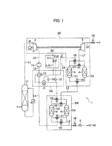
[FIG. 1] FIG. 1 is a schematic configuration diagram illustrating
a carbon dioxide recovery apparatus according to one embodiment
of the present disclosure.
DESCRIPTION OF EMBODIMENTS
[0020]
The pressure swing adsorption (PSA) method is a method
for separating and removing a specific component in a mixed gas
by utilizing adsorption and desorption of the specific component
to and from an adsorbent caused by pressure fluctuation, and
it can be utilized to recover carbon dioxide from a carbon dioxide
containing gas such as a combustion exhaust gas, by using a
material capable of adsorbing carbon dioxide as the adsorbent.
Increasing the pressure of an exhaust gas supplied to the
adsorbent to a relatively high pressure (adsorption pressure)
causes the adsorbent to adsorb carbon dioxide, and reducing the
pressure to a relatively low pressure (desorption pressure)
causes the adsorbent to desorb and release the adsorbed carbon
dioxide. A carbon dioxide-removed gas and concentrated (or
refined) carbon dioxide are obtained from the exhaust gas by
repeating such increase and decrease of the pressure to cause
the adsorbent to adsorb and desorb (release an adsorbate) carbon
dioxide in the exhaust gas.
[0021]
In order to prevent inhibition of selective adsorption
ability in a separator using the PSA method, the exhaust gas
CA 03017323 2018-09-10
8
subjected to drying treatment is supplied to the separator. A
hygroscopic agent is used in the drying treatment. The used
hygroscopic agent can be regenerated and used repeatedly by
supplying heat or dry gas. A residual gas obtained after the
separation of carbon dioxide in the separator contains
substantially no moisture and can be thus utilized to regenerate
the hygroscopic agent. However, the amount of the residual gas
obtained after the carbon dioxide separation depends on the
amount of carbon dioxide contained in the exhaust gas and
fluctuates depending on changes in the amount of carbon dioxide
contained in the exhaust gas. In an actual processing condition,
when the amount of the residual gas supplied to the hygroscopic
agent as a regeneration gas fluctuates, this fluctuation
unexpectedly affects the regeneration of the hygroscopic agent.
In order to stably repeat the regeneration of the hygroscopic
agent, it is effective to achieve a configuration which can
supply the regeneration gas to the hygroscopic agent at a
constant amount irrespective of the fluctuation in the amount
of carbon dioxide contained in the exhaust gas and the
fluctuation in the amount of residual gas.
[0022]
In the present disclosure, the residual gas obtained after
the separation of carbon dioxide, in the recovery of carbon
dioxide utilizing the separation using the PSA method, is
supplied as the regeneration gas to be used for regeneration
of the hygroscopic agent for drying. And, in this case, a
supplement gas is supplied from the outside as necessity arises
such that the supply flow rate of the regeneration gas is constant.
Thus a carbon dioxide recovery method and recovery apparatus
configured as described above are proposed. The carbon dioxide
recovery method according to an embodiment of the disclosure
and the carbon dioxide recovery apparatus for executing this
method are described below with reference to the drawing.
[0023]
FIG. 1 is a schematic configuration diagram illustrating
an embodiment of the carbon dioxide recovery apparatus in the
CA 03017323 2018-09-10
9
present disclosure. The recovery apparatus 1 has: a separator
SP which separates carbon dioxide from a gas by using the PSA
method; a dryer DR which dries the gas to be supplied to the
separator SP; a regeneration system RG which supplies a residual
gas from which carbon dioxide has been removed to the dryer DR
as a regeneration gas to be used for regeneration of a hygroscopic
agent H in the dryer DR; and a supplement system SU which supplies
a supplement gas from the outside to the residual gas as necessary
such that the flow rate of the residual gas is a predetermined
rate.
[0024]
The separator SP has at least one pair of columns Cl, C2
containing the adsorbent A. The separator SP is also provided
with a compressor 3 which serves as a pressurizer for applying
to a gas G a pressure at which carbon dioxide is adsorbed to
the adsorbent A and an expander 5 which serves as a pressure
reducer for reducing the pressure in the columns Cl, C2 to a
pressure at which carbon dioxide can be desorbed from the
adsorbent A. Operations of the compressor 3 and the expander
can cause pressure fluctuation in the columns Cl, C2, and the
adsorption and desorption of the carbon dioxide to and from the
adsorbent A caused by the pressure fluctuation can be utilized
to separate carbon dioxide from the gas G. As a result,
highly-concentrated carbon dioxide C and a residual gas G' from
which carbon dioxide has been removed are discharged from the
separator SP. The adsorptive separation of carbon dioxide can
be performed by using a single column. However, in such a case,
the gas G is intermittently supplied according to switching
between the adsorption and the desorption, and the processing
is intermittent.
[0025]
The dryer DR includes the hygroscopic agent H for drying
the gas G to be supplied to the separator SP. The hygroscopic
agent H is contained in at least one pair of columns C3, C4.
The gas G pressurized by the compressor 3 is dehumidified by
the hygroscopic agent H in the dryer DR and then supplied to
CA 03017323 2018-09-10
the separator SP. The hygroscopic agent H absorbing moisture
can be regenerated by being heated or being supplied with a dry
gas.
[0026]
Since the gas G supplied to the separator SP is dry, the
residual gas G' obtained after the removal of carbon dioxide
in the separator SP contains substantially no moisture.
Accordingly, the residual gas G' can be used as the regeneration
gas to be used for regeneration of the hygroscopic agent H in
the dryer DR, and the regeneration system RG supplies the
residual gas G' discharged from the separator SP to the dryer
DR as the regeneration gas to be used for regeneration of the
hygroscopic agent H in the dryer DR. A device for heating the
residual gas G' is provided to improve the regeneration
efficiency, and the recovery apparatus 1 is designed to have
a configuration with improved heat efficiency.
[0027]
The residual gas G' discharged from the separator SP is
decreased to be less than the gas G by an amount corresponding
to the removed carbon dioxide. In other words, the discharge
amount of the residual gas G' fluctuates depending on the amount
of carbon dioxide contained in the gas G supplied to the recovery
apparatus 1. When the amount of carbon dioxide contained in the
gas G is large, the flow rate of the residual gas G' decreases
greatly and shortage of the regeneration gas occurs.
Particularly, when the amount of carbon dioxide contained in
the gas G is 50% or the vicinity, the shortage of the regeneration
gas becomes unignorable. Accordingly, in order to prevent the
shortage of the regeneration gas due to the fluctuation in the
amount of carbon dioxide contained in the gas G, there is provided
the supplement system SU which constantly maintains the amount
of regeneration gas at the predetermined amount by adding a
supplement gas N to the residual gas G' from the outside as
necessity arises. As the supplement gas N supplied from the
outside, there is used a gas which has a moisture content usable
for the regeneration of the hygroscopic agent H and which does
CA 03017323 2018-09-10
11
not substantially affect the performance of the hygroscopic
agent. A gas consisting of an inert component such as nitrogen
is thus preferably used as the supplement gas N. The supplement
gas N does not have to be a gas consisting of a single component
and may have a mixed composition of multiple components as long
as the gas is usable for the regeneration of the hygroscopic
agent H. For example, since a nitrogen gas discharged from an
oxygen production equipment (ASU: air separation unit) has a
water content of about 1 to 2 ppm, this nitrogen gas can be used
as it is and is useful as the supplement gas N. Moreover, air
or the like discharged from the air-conditioned facilities, etc.
is also dry and can be utilized as the supplement gas N. The
supplement system SC supplies the supplement gas N from the
outside to the residual gas G' depending on the flow rate of
the residual gas G discharged from the separator SP, and =the
flow rate of the regeneration gas supplied to the dryer DR is
thus maintained at a constant rate. Hence, the regeneration gas
is constantly and stably supplied to the dryer DR, and the
separator SP is avoided from being affected by regeneration
failure of the hygroscopic agent H.
(00281
A specific configuration of the recovery apparatus 1 in
FIG. 1 is described below. It is noted that broken lines in FIG.
1 illustrate electrical connections. The recovery apparatus 1
includes a cooler 11. The gas G containing carbon dioxide is
first supplied to the cooler 11. The cooler 11 is equipment for
cooling the gas G discharged from the combustion facility or
the like at a high temperature to a temperature suitable for
processing in the subsequent equipment and is configured to cool
the gas G to a temperature of about 50 C or less, preferably
about 40 C or less at the outlet. The temperature of the
combustion exhaust gas at the inlet is generally about 100 to
200 C. Since the volume of the gas decreases by cooling, this
makes it possible to increase the processing amount in subsequent
equipment. A coolant may be any generally-used coolant such as
water, air, or a coolant for refrigeration cycle. Regarding the
CA 03017323 2018-09-10
12
contact with the coolant, any type of cooling may be employed,
such as those of a direct-contact type such spraying, gas-liquid
contact using a packing, etc., those of indirect-contact type
using a condenser, a heat exchanger, or the like. In this
embodiment, a scrubber which cools the gas G by bringing the
gas G into direct contact with cooling water is provided as the
cooler 11. The direct-contact cooling using cooling water is
excellent in economy and cooling efficiency and also has a
function of cleaning means for removing fine solid matters such
as dust and acid substances such as chlorides and sulfur oxides,
from the gas G.
[0029]
The cooler 11 is connected to the compressor 3 via a flow
passage Li. The gas G whose temperature is adjusted to a suitable
temperature by the cooler 11 is supplied to the compressor 3
to be compressed, and the pressure thereof is increased. The
compressor 3 is operated by a power source M such as, for example,
a motor, and applies to the gas G a pressure required for the
adsorption of the carbon dioxide in the subsequent separator
SP. Specifically, the compressor 3 pressurizes the gas G to a
pressure such that the partial pressure of the carbon dioxide
in the gas G supplied to the separator SP reaches the adsorption
pressure (relatively high pressure) . The pressure to be applied
by the compressor 3 is thus determined based on the carbon dioxide
concentration in the gas G and the adsorption pressure. The
adsorption pressure is appropriately set based on an adsorption
isotherm of carbon dioxide on the adsorbent A used in the
separator SP. The pressurization pressure of the gas G is thus
set, depending on the carbon dioxide concentration in the gas
G, to a pressure at which the carbon dioxide partial pressure
in the gas G reaches the adsorption pressure. Hence, the
pressure of the pressurized gas G is expressed by the following
formula: pressure = 100 X adsorption pressure/carbon dioxide
concentration in gas G (M. The adsorption pressure employed
in the separator SP is preferably a pressure equal to or higher
than a threshold indicated by the adsorption isotherm on the
CA 03017323 2018-09-10
13
adsorbent and varies depending on the used adsorbent. However,
the adsorption pressure can be generally set to about 0.3 to
0.6 MPa. Any pressurizing devices capable of generating flow
pressure that can pressurize the gas G such that the partial
pressure of carbon dioxide reaches an appropriate adsorption
pressure can be used as the pressurizer, and a pressure pump,
a compressor, a blower, and the like can be given as examples
of such devices. Accordingly, the compressor 3 can be replaced
with other pressurizing device which can pressurize the gas G
such that the partial pressure of carbon dioxide in the gas G
reaches the adsorption pressure. However, since a pressurizing
device that the applied pressure is relatively small can be used
in the PSA method as compared with the conventional method, the
compressor and the blower can be preferably utilized and the
compressor is most preferable. The pressure applied to the gas
G by the compressor 3 can be maintained in the separator SP by
providing a pressure regulating valve downstream of the
separator SP. The pressure of the gas G can be adjusted by
controlling the pressure regulating valve. In the embodiment,
the pressurization pressure can be adjusted by using a pressure
regulating valve V9 (see below) provided on the regeneration
gas discharge side of the dryer DR. The pressurization in the
compressor 3 increases the temperature of the gas G. For example,
when the gas G whose temperature is 40 C and whose carbon dioxide
concentration is 80% (volume percent) is pressurized to about
0.5 MPa, the partial pressure of carbon dioxide is about 0.4
MPa which is suitable as the adsorption pressure, and the
temperature of the gas G in this case is about 190 C. When the
pressurization pressure of the gas G in the compressor 3 is
appropriately adjusted depending on the concentration of carbon
dioxide as described above, the temperature of the gas G after
the pressure increase is generally increased to about 180 to
200 C.
[00301
When nitrogen oxides are contained in the gas G, the
nitrogen oxides are preferably removed as much as possible in
CA 03017323 2018-09-10
14
consideration of effects on selective adsorption ability of the
adsorbent A in the separator SP. For this purpose, a denitrator
13 is provided and the compressor 3 is connected to the denitrator
13 via a flow passage L2. The denitrator 13 may utilize any
method appropriately selected from denitration methods
generally used for denitration of exhaust gas such as dry
denitration using a solid absorbent, adsorbent, or catalyst or
wet denitration using an aqueous liquid containing a basic
substance. For example, a catalyst which decomposes a nitrogen
oxide into nitrogen by reacting the nitrogen oxide with ammonia
is preferably used. Moreover, nitrogen monoxide included in the
nitrogen oxides is very low in water solubility and is difficult
to dissolve and remove with water alone. However, in the
embodiment of FIG. 1, since the gas G is pressurized by the
compressor 3, removal by dissolution into water can be performed
by utilizing reaction progress caused by the pressurization.
Specifically, oxidation of nitrogen monoxide progresses in the
pressurized gas G and nitrogen monoxide is converted to nitrogen
dioxide with high water solubility. In addition, water vapor
in the gas G is condensed by the pressurization and the nitrogen
oxides contained in the gas G dissolve into the condensate water
as nitrogen dioxide. Accordingly, denitration processing of
the gas G can be performed by separating and removing the
condensate water from the pressurized gas G with use of a
gas-liquid separator or the like. In this processing method,
a basic substance is unnecessary and the water content of the
gas G is reduced. Accordingly, the burden on the dryer DR in
the subsequent stage is reduced.
[0031]
The denitrator 13 is connected to a heat exchanger 15 via
a flow passage L3 and the denitrated gas G is cooled in the heat
exchanger 15 by the residual gas G' discharged from the separator
SP. The residual gas G' is thereby heated to a temperature
suitable for utilization as the regeneration gas (details are
described later) . It is noted that, in the case where the heat
exchanger 15 is corrosion resistant or the gas G contains a
CA 03017323 2018-09-10
relatively small amount of nitrogen oxides, the aforementioned
denitrator 13 can be arranged in the stage subsequent to the
heat exchanger 15. In that a case, the amount of condensate water
separated and removed by cooling of the pressurized gas G
increases. Accordingly, the water content of the gas G is
reduced and the burden on the drying treatment in the dryer DR
in the subsequent stage is reduced.
[0032]
The heat exchanger 15 is connected to the dryer DR via
a flow passage L4, and the cooled gas G is subjected to the drying
treatment by the dryer DR. The dryer DR is equipment for removing
moisture from the gas G to prevent damage and functional decline
of the adsorbent A used in the separator SP, and is particularly
important in the case where the cooler 11 and the denitrator
13 in the previous stages are configured by using a wet type
device. The dryer DR has the columns 03, C4 containing the
hygroscopic agent H therein. The gas G is dehumidified by being
brought into contact with the hygroscopic agent H, and the gas
G with low humidity is supplied to the separator SP via a flow
passage L5. The hygroscopic agent H may be appropriately
selected and used from commonly used desiccant materials such
as silica gel, alumina gel, molecular sieve, zeolite, activated
carbon and the like. A hygroscopic agent which can be easily
regenerated by heating such as silica gel and the like is
economically advantageous and can form a temperature swing
moisture absorbing tower. Forming the dryer DR by using one pair
or more of moisture absorbing columns loaded with the hygroscopic
agent H enables alternate performance of moisture absorption
of the gas G and the regeneration of the hygroscopic agent H
in each moisture absorbing column by supplying the gas G and
the high-temperature regeneration gas alternately to the
moisture absorbing column. In other words, the drying treatment
and the regeneration of the hygroscopic agent H can be repeatedly
and continuously performed without stopping the processing of
the gas G. This is achieved by performing switching control of
switching valves V1, V2, V3, V4. Controlling the switching
CA 03017323 2018-09-10
16
valves V1, V2 such that the flow passages L4, L5 communicate
with one of the columns C3, 04 causes the gas G supplied from
the flow passage L4 to be dehumidified in the one of the columns
03, 04 and supplied to the separator SP via the flow passage
L5. At this time, the connection of the switching valves V3,
V4 is controlled such that the regeneration gas supplied to the
dryer DR flows through the other column and is discharged from
a flow passage L6. By reversing the connection of the switching
valves V1, V2, V3, V4, the moisture absorption and the
regeneration in the columns 03, 04 are switched. The switching
valves V1, V2, V3, V4 may be configured to be automatically
switched depending on the moisture concentration of the gas G
discharged from the flow passage L5. For example, such a
configuration can be given that a concentration sensor is
provided in the flow passage L5 to be electrically connected
to the switching valves V1, V2, V3, V4 and that respective
switching of the switching valves V1, V2, V3, V4 is performed
based on an increase in the moisture concentration detected by
the concentration sensor so as to change the column communicating
with the flow passage L4 and the flow passage L5.
[0033]
A main portion of the separator SP is configured by the
columns Cl, 02 containing the adsorbent .A. for separating carbon
dioxide from the gas according to the PSA method. Supplying the
gas G causes carbon dioxide contained in the gas G to be adsorbed
to the adsorbent A and the residual gas G' with less carbon
dioxide is discharged. Specifically, the gas G supplied from
the dryer DR to the separator SP via the flow passage L5 is
separated in the columns Cl, 02 into concentrated or refined
carbon dioxide C and the residual gas G' which is a de-carbon
dioxide gas that carbon dioxide has been reduced or removed.
The separator SP is connected to the expander 5 and a liquefying
device (not illustrated) via a flow passage L7 and is also
connected to the dryer DR via flow passage L8. The residual gas
G' from which carbon dioxide has been removed by the adsorbent
A flows out from the column to be released from the separator
CA 03017323 2018-09-10
17
SP and is supplied to the dryer DR via the flow passage 58
connected to the dryer DR. Meanwhile, when the column is made
to communicate with the flow passage L7 by connection switching
of the switching valves, a pressure decrease by the expander
causes the carbon dioxide adsorbed on the adsorbent A to be
desorbed, and the concentrated or refined carbon dioxide C is
supplied to the liquefying device via the flow passages L7, L9.
The expander 5 is connected to cooperate with the compressor
3, and the flow pressure generated at the pressure release in
the expander 5 is recovered as power and is utilized as a part
of the drive power for the compressor 3. Therefore, energy
consumed in the power source M of the compressor 3 can be reduced.
For the connection between the expander 5 and the compressor
3, a known method such as shaft connection or integral connection
can be appropriately utilized. For example, such a form that
a scroll compressor and a scroll expander, which are scroll type
fluid machines, are used in a coaxial state can be employed.
10034]
The adsorbent A contained in the columns Cl, C2 is an
adsorbent capable of selectively adsorbing carbon dioxide in
the PSA method. The desorption pressure for activated carbon
and zeolite which are conventionally known as materials capable
of adsorbing carbon dioxide is a negative pressure. Thus, a
vacuum pump is necessary for desorption of carbon dioxide.
Meanwhile, in metal-organic frameworks which are recently
studied as an adsorbent, the adsorption isotherm indicating the
relationship between the pressure of adsorbate and adsorption
equilibrium is curved in an S shape and has an abrupt rising
portion around a certain pressure. Accordingly, even when the
pressure difference between the adsorption pressure and the
desorption pressure is small, the difference in the equilibrium
adsorption amount (= adsorption capacity) can be made large.
In the embodiment of FIG. 1, metal-organic frameworks (M0Fs)
capable of selectively adsorbing carbon dioxide are usable as
the adsorbent A. The metal-organic frameworks are porous
materials also called porous coordination polymers (PCPs) . In
CA 03017323 2018-09-10
18
the metal-organic frameworks, a complex formed by coordinate
bonding of metal ion and organic ligand forms a base of a
framework of a porous structure, and the metal-organic
frameworks function as the adsorbent by utilizing this porous
structure. Examples of the metal-organic frameworks include
[0u(4,41-dihydroxybipheny1-3-carboxy)2(4,4'-bipyridy1)],,
[Cu(PF6 )2(1,2-bis(4-pyridyl)ethane)in,
[Cu(0FS0312(1,3-bis(4-pyridyl)propane)2],,
{ [Cu (PF6-) (2,2-bis (4-pyridyl) ) ]PF6-}n,
[Cu2(PFC: ) 2 ( 4, 4 ' -pyridyl) propane ) 2] [Cu2 (PF6-) 2 (PYridine ) 1
4 nr
[M2(2,5-dioxide-1,4-benzenedicarboxylate)] (wherein M in the
formula is Mg2+, Mn2', Ni2', Fe2+, or Zn2'-),
[Cu(4,4'-dioxidebipheny1-3- carboxylate)2(4,4'-bipyridyl)ln,
[Zn40(4,4',4"-(benzene-1,3,5-triyl-tris(benzene-4,1-diy1)tri
benzoate)], and the like. Alternatively, metal-organic
framework with adsorptivity for carbon dioxide appropriately
may be selected and utilized from commercially-available
metal-organic frameworks. Multistage adsorption processing
can be executed by using multiple pairs of columns. In such a
case, different types of metal-organic frameworks may be used
in the respective pairs to provide adsorption performances
corresponding to the respective types. Some metal-organic
frameworks exhibit adsorptivity for plural kinds of gases. In
such metal-organic frameworks, the pressure at the threshold
in the adsorption isotherm generally varies among the types of
gases, and selective adsorption for carbon dioxide can be
suitably carried out by appropriate pressure setting.
[0035]
In each of the columns Cl, 02, carbon dioxide contained
in the gas G is adsorbed to the adsorbent A when the gas G is
supplied at the pressure at which the partial pressure of the
carbon dioxide is equal to the adsorption pressure (relatively
high pressure). Meanwhile, when the pressure drops to the
desorption pressure (relatively low pressure), carbon dioxide
is desorbed from the adsorbent A. and is released. For example,
when [Cu(4,4'-dihydroxybipheny1-3-0arb0xy)2(4,4'-bipyridyl)ln
CA 03017323 2018-09-10
19
is used as the metal-organic framework, the adsorption
equilibrium changes abruptly around 0.25 MPa. Accordingly, it
is possible to set the adsorption pressure within a higher
pressure range (> 0.25 MPa) and set the desorption pressure
within a lower pressure range (< 0.25 MPa) , where the border
is set at the pressure value (threshold) at which the equilibrium
adsorption amount changes abruptly. Such setting can make the
difference between the equilibriums adsorption amounts (--
adsorption capacity) large even when the pressure difference
between the adsorption pressure and the desorption pressure is
small. Accordingly, load on the device due to the pressure swing
between the adsorption pressure and the desorption pressure is
greatly reduced from that in the conventional technique, and
burden of increasing the durability of the device structure can
be reduced. Moreover, since the desorption pressure can be set
to the atmospheric pressure or a positive pressure (pressure
higher than the atmospheric pressure) instead of a negative
pressure, the adsorption pressure and the desorption pressure
can be set and adjusted by using the pressure regulating valves,
without using a vacuum pump. Thus, energy which will be
otherwise consumed by the vacuum pump can be saved, and it is
possible to eliminate a limit on processing capacity of the
recovery apparatus imposed by the performance of the vacuum pump
that is a problem in the conventional PSA method.
[0036]
The series of operations of supplying the gas G and
reducing the pressure are repeated so that the adsorption and
desorption of carbon dioxide are alternately performed in the
two columns Cl, C2, thereby the separation of carbon dioxide
from the gas G and the recovery of carbon dioxide are alternately
and repeatedly performed in each column. This is achieved by
performing switching control of switching valves V5, V6, V7.
Controlling the switching valves V5, V6 such that the flow
passage L5 and the flow passage L8 communicate with one of the
columns Cl, 02 causes carbon dioxide in the gas G supplied from
the flow passage L5 to be adsorbed and removed in the one of
CA 03017323 2018-09-10
the columns Cl, C2 and causes the residual gas G1 to be discharged
from the flow passage L8. At this time, the connection of the
switching valve V7 is controlled such that the other column
communicates with the flow passage L7 and the expander 5. The
pressure in the other column is thereby reduced to the desorption
pressure and carbon dioxide is released from the adsorbent A.
Thereafter, the connection of the switching valves V5, V6, V7
is reversed to switch the adsorption and the desorption in the
columns Cl, C2. Carbon dioxide C is thus recovered alternately
from the paired columns in the separator SP via the flow passage
L9 by using the gas G continuously supplied from the compressor
3 via the dryer DR. The recovered carbon dioxide C is eventually
liquefied. The desorption pressure in the columns Cl, C2 can
be adjusted by using a pressure regulating valve V8 in the flow
passage L9. The residual gas G' from which carbon dioxide has
been removed is returned to the dryer DR via the flow passage
L8. The carbon dioxide concentration in the residual gas G' can
be detected by installing a carbon dioxide concentration sensor
in the flow passage L8, that is downstream of the switching valve
V6. An increase in the carbon dioxide concentration due to
breakthrough of the adsorbent A can be thus detected.
Accordingly, when the concentration sensor is electrically
connected to the switching valves V5, V6, V7 and the switching
valves VS, V6, V7 are set to be automatically switched based
on the detected carbon dioxide concentration, switching between
the adsorption and the desorption can be performed at an optimal
timing such that the adsorption capacity of the adsorbent A is
effectively utilized at the maximum.
[0037]
The liquefaction of carbon dioxide C can be performed by
utilizing a compression device for compressing the carbon
dioxide C and a cooling device using a heat exchanger, and the
liquefaction device can be configured by using these devices.
The concentrated or refined carbon dioxide C recovered in the
separator SP is liquefied by being cooled to a temperature equal
to or lower than the boiling curve, preferably -20 to -50 C and
CA 03017323 2018-09-10
21
by being pressurized and compressed. The liquefied carbon
dioxide C is preferably prepared in a supercritical state and
liquefied carbon dioxide C generally refined to a purity of about
95 to 99% is possibly obtained.
[0038]
The regeneration system RG which uses the residual gas
G discharged from the separator SP as the regeneration gas
includes the flow passage L8 and a heating device for heating
the residual gas G' to a high temperature. Specifically, the
aforementioned heat exchanger 15 is arranged to perform heat
exchange between the gas G in the flow passage L3 and the residual
gas G' in the flow passage L8. Since the temperature of the gas
G is increased by the pressure applied in the compressor 3, the
residual gas G' released from the separator SP is heated by heat
exchange through indirect contact with the high-temperature gas
G in the heat exchanger 15. The heat exchanger 15 thus cools
the compressed gas G in the flow passage L3 while heating the
residual gas G' in the flow passage L8 by recovering and utilizing
the heat of the gas G. In other words, the residual gas G' serves
as a heat medium which carries heat energy of the compressed
gas G to the dryer DR. The high-temperature gas G is cooled to
about 50 to 70 C in the heat exchanger 15 and pumped to the dryer
DR and the separator SP. The cooled temperature of the gas G
can be about 30 to 40 C or lower depending on the heat exchange
rate of the heat exchanger 15. The residual gas G' at about 20
to 40 C which is returned from the separator SP is heated to
about 150 to 200 C. The heat exchanger 15 can be configured by
using a known gas-to-gas heat exchanger. The heat exchanger 15
may be of any form such as a counter-flow type, a parallel-flow
type, or a crossflow type, and can be appropriately selected
from, for example, a static heat exchanger, a rotary regenerative
heat exchanger, a periodic flow regenerative heat exchanger,
and the like. The heated residual gas G' is supplied to the
columns C3, C4 as the regeneration gas and the moisture is thereby
released from the used hygroscopic agent H.
[0039]
CA 03017323 2018-09-10
22
The regeneration system RG includes, on the flow passage
L8, a heater 17 which is provided downstream of the heat exchanger
15 and a detector 19 which is provided downstream of the heater
17, in order to add.itionally heat the residual gas G' as necessary.
The detector 19 detects the temperature of the regeneration gas
to be supplied to the dryer DR. The heater 17 is electrically
connected to the detector 19 and is controlled depending on the
temperature detected by the detector 19 to heat the residual
gas G' obtained after the heat exchange when the temperature
of the residual gas G has not reached a temperature suitable
as the regeneration gas. The regeneration gas supplied to the
dryer DR is a high-temperature dry gas whose temperature is about
150 to 200 C and which contains almost no moisture and has a
dew point of about -90 to -60 C. The regeneration gas (residual
gas G') containing moisture due to the regeneration of the
hygroscopic agent H in the dryer DR is discharged from the flow
passage L6 to the outside via the pressure regulating valve V9
and a silencer X, and the pressure of the regeneration gas
(residual gas G' ) is released to become the atmospheric pressure.
The pressure applied by the compressor 3 is maintained over the
dryer DR and the separator SP to the pressure regulating valve
V9 in the flow passage L6, and the pressure regulating valve
V9 adjusts the pressure of the gas G and the residual gas G'.
[0040]
The flow rate of the residual gas G' discharged from the
separator SP is lower than the flow rate of the gas G supplied
to the recovery apparatus 1 by an amount corresponding to the
recovered carbon dioxide C. In other words, the larger the
amount of carbon dioxide contained in the gas G is, the lower
the flow rate of the regeneration gas, that is the residual gas
G' is. When the flow rate of the regeneration gas falls, the
time required for the regeneration of the hygroscopic agent
becomes longer. Accordingly, there may be a case where it is
difficult to sufficiently make use of the moisture absorption
capacity of the hygroscopic agent. In order to improve this and
perform switching between the dehumidification and the
CA 03017323 2018-09-10
23
regeneration at an optimal timing, it is important that the
regeneration gas is supplied at such a flow rate that the
hygroscopic agent H can be regenerated in a time shorter than
a time required for the hygroscopic agent H in the drying
treatment to reach its moisture absorbent capacity. In this
respect, the recovery apparatus 1 includes the supplement system
SU for supplementing the residual gas G' from the outside by
an amount corresponding to shortfall of the residual gas G' as
the regeneration gas. The supplement system SU includes a flow
passage L10 which supplies a supplement gas N from the outside
and a flow regulating valve V10 which is provided in the flow
passage L10, and the flow passage 110 is connected to the flow
passage 18. An electrically-controllable valve such as an
electromagnetic valve is used as the flow regulating valve V10.
The flow regulating valve V10 is electrically connected to a
flowmeter 21 installed in the flow passage L8 downstream of a
connection point between the flow passage 110 and the flow
passage L8.
[0041]
The flow passage L10 is a line which supplies the external
supplement gas N to the residual gas G' in the flow passage 18
to supplement the residual gas G'. Agas with amoisture content
usable for the regeneration of the hygroscopic agent H,
preferably with a moisture amount of about 1 ppm or less is used
as the supplement gas N. For example, a nitrogen gas discharged
from an oxygen production equipment (ASU: air separation unit)
or the like is preferably used as the supplement gas N. It is
note that, since the residual gas G' is pressurized, the
supplement gas N is supplied at the same pressure as the residual
gas G'. The flow regulating valve V10 is controlled depending
on the flow rate detected by the flowmeter 21 and adjusts the
flow rate of the supplement gas N such that, when the flow rate
of the regeneration gas detected by the flowmeter 21 is below
the predetermined flow rate, the supplement gas N is supplied
to maintain the flow rate of the regeneration gas supplied to
the dryer DR at the predetermined flow rate. The supplement gas
CA 03017323 2018-09-10
24
N is thus added to the residual gas G' from the outside depending
on the flow rate of the residual gas G' and the total flow rate
of the residual gas G' and the supplement gas N is maintained
at the constant flow rate. In this respect, the regeneration
is generally preferably performed such that the supply flow rate
of the regeneration gas is about 30% to 70% of the supply flow
rate of the gas G to the hygroscopic agent H. A flow rate at
which such a percentage can be achieved is thus preferably set
as the predetermined rate. As described above, the supply flow
rate of the regeneration gas is maintained at the predetermined
rate by adjusting the supply rate of the supplement gas with
the flow regulating valve V10. The regeneration gas is thereby
constantly and stably supplied to the dryer DR and the separator
SP is avoided from being affected by efficiency decrease in the
drying treatment and the regeneration failure of the hygroscopic
agent H.
[0042]
The supply of the regeneration gas can be adjusted based
on the difference (G-G') between the flow rate of the gas G at
the entrance of the separator SP and the flow rate of the residual
gas G' at the exit of the separator SP. In this case, the
configuration may be such that detectors which measure the flow
rates of the gas G and the residual gas G' at the entrance and
exit of the separator SP are provided and the flow rate adjustment
valve V10 is controlled based on detection values of these
detectors.
[0043]
If the gas G to be supplied to the aforementioned recovery
apparatus 1 is already subjected to water cleaning processing
or cooling processing in the other equipment and requires no
cooling or removable of unwanted matters, the cooler 11 may be
omitted. When the cooling of the gas G needs to be enhanced from
the view point of achieving the appropriate temperature in the
dryer DR and the separator SP, a cooler is preferably added at
an appropriate position such as on the flow passage L4 or the
flow passage L5 downstream of the heat exchanger 15, and a
CA 03017323 2018-09-10
water-cooled cooler which uses cooling water at about 5 to 25 C
as coolant can be used to cool the gas G c to a temperature of
about 20 to 30 C or lower.
[0044]
Moreover, the number of columns containing the hygroscopic
agent H in the dryer DR may be appropriately changed depending
on the moisture absorption rate, the moisture absorption
capacity, the regeneration rate, and the like of the used
hygroscopic agent H so as to perform appropriate drying treatment.
The separator SP may also have a multistage configuration in
which the number of pairs of columns is increased to increase
the number of stages of adsorption-desorption processing
depending on the separation selectivity of the adsorbent A.
This can improve the purity of the recovered carbon dioxide.
For example, when a pair of columns similar to the columns Cl,
C2 is additionally provided on the flow passage L7, the
separation performance is improved by adsorptive separation in
the second stage. In this case, the residual gas separated from
carbon dioxide in the second-stage columns can be preferably
returned to adsorptive separation processing in the first-stage
columns.
[0045]
Alternatively, the configuration may be such that a
concentration sensor is provided in the flow passage L9 as a
detector which detects the carbon dioxide concentration and the
recovered carbon dioxide C is returned to the flow passage L5
when the concentration of the recovered carbon dioxide C is low.
Low-concentration carbon dioxide is thereby supplied to the
columns Cl, C2 together with the gas G and the concentration
of carbon dioxide obtained from one pair of columns can be
increased.
[0046]
In the aforementioned configuration, a computation
processing device such as a CPU may be utilized to manage
information detected by the detectors and the sensors while
performing automatic control of the switching valves based on
t
26
the detected information. This enables complex processing such
as operation correction through compensation based on the
detected information, abnormality response, and the like.
[0047]
The carbon dioxide recovery method performed in the
recovery apparatus 1 configured as described above includes
separation processing, drying treatment, regeneration
processing, and supplement processing as main processing. In
the separation processing, carbon dioxide is separated from the
gas by utilizing the adsorption and desorption of carbon dioxide
to and from the adsorbent caused by the pressure fluctuation,
and the residual gas from which carbon dioxide has been removed
is discharged. In the drying treatment, the gas to be supplied
to the separation processing is dried by using the hygroscopic
agent. In the regeneration processing, the residual gas
discharged in the separation processing is supplied to the
hygroscopic agent used in the drying treatment, as the
regeneration gas to be used for regeneration of the hygroscopic
agent. In the supplement processing, the supplement gas is
supplied from the outside depending on the flow rate of the
residual gas discharged from the separator such that the flow
rate of the regeneration gas is the predetermined rate. In
detail, the following operations are performed.
[0048]
The gas G to be supplied is subjected to the cooling
processing in the cooler 11 to be cooled to a temperature of
about 50 C or lower, preferably about 40 C or lower, and it is
then pressurized to the pressure at which the separation of
carbon dioxide is performed (pressure at which the partial
pressure of carbon dioxide in the gas G reaches the adsorption
pressure (relatively high pressure) ) . The pressure generally
employed in this pressurization is a pressure at which the
adsorption pressure is about 0.3 to 0.6 MPa. The temperature
of the pressurized gas G is increased to about 180 to 200 C and
the gas G is subjected to the denitration processing in the
denitrator 13 and the cooling by the heat exchanger 15 before
CA 3017323 2018-10-18
CA 03017323 2018-09-10
27
being subjected to the separation processing using the adsorbent,
to be cooled to a temperature of about 50 C or lower, preferably
about 40 C or lower, more preferably about 30 C or lower.
Thereafter, the gas G is subjected to the drying treatment by
the dryer DR and the moisture content thereof is reduced to about
1 ppm or less.
[0049]
The gas G subjected to the drying treatment is subjected
to the adsorption of carbon dioxide using the adsorbent A in
the separator SP and is thereby separated into carbon dioxide
C and the residual gas G' (separation processing) . The
adsorption reaction in which the metal-organic framework
adsorbs carbon dioxide is an exothermic reaction and the
desorption reaction is an endothermic reaction. Accordingly,
the temperature may fluctuate by 20 C at the maximum due to
repeating of the adsorption and the desorption. Thus, in order
to achieve quick adsorption of carbon dioxide, it is desirable
to maintain the temperature in the adsorption at a low
temperature. The gas G to be supplied to the columns Cl, C2 in
the separation processing is cooled in advance in the heat
exchanger 15 as described above. However, if the temperature
of the gas G is higher than the temperature suitable for the
separation processing, the gas G may be preferably cooled as
necessary by utilizing an appropriate cooler provided in the
stage prior to the separation processing. The cooling method
of the gas G is not limited to a particular method provided that
the method involves no humidification, and a method
appropriately selected from well-known indirect contact cooling
techniques such as water cooling and air cooling may be suitably
employed. The gas G can be cooled in an excellent manner by
performing water cooling.
[0050]
In the separation processing, for example, when the gas
G with a carbon dioxide concentration of 60%, a temperature of
20 C, and a pressure of 0.6 MPa is supplied to one of the columns
Cl, C2, the adsorption of carbon dioxide starts at the adsorption
CA 03017323 2018-09-10
28
pressure of 0.36 MPa. The gas released from this column is
discharged via the flow passage 18 as the residual gas G'. The
carbon dioxide concentration of the residual gas is extremely
low until the adsorption amount of the carbon dioxide approaches
the adsorption capacity of the adsorbent A. When the adsorbent
A approaches the breakthrough (adsorption saturation), the
adsorption rate decreases and the carbon dioxide concentration
in the residual gas G' thereby starts to increase. When the
adsorbent A reaches the breakthrough, the carbon dioxide
concentration of the residual gas G' reaches 60% that is the
original carbon dioxide concentration. In the other column, the
carbon dioxide adsorbed on the adsorbent A is released by
depressurization to the desorption pressure. The pressure is
controlled to the desorption pressure of about 0.2 MPa by the
pressure regulating valve V8. The concentration of carbon
dioxide discharged from the column to the flow passage 17 is
increased from 60% by the desorption of carbon dioxide from the
adsorbent A, and concentrated carbon dioxide C is recovered from
the flow passage L9. It is noted that, since the temperature
of the adsorbent A falls due to the endothermic reaction in the
desorption, the temperature inside the adsorbent A in the
adsorption becomes higher than that in the desorption even when
the supplied gas G is cooled to a constant temperature. Hence,
the rate at which the adsorbent A takes in carbon dioxide in
the adsorption is higher than the rate of release in the
desorption and can be generally about 1.2 times the rate of
release. Accordingly, the release of carbon dioxide from the
adsorbent A on the desorption side substantially continues until
the adsorbent A on the adsorption side reaches the breakthrough.
[0051]
In the separation processing, the carbon dioxide
concentration in the gas released from the adsorbent in the
desorption can rise from the carbon dioxide concentration in
the gas G and reach a purity of 95% (volume percent) or more.
For example, when the carbon dioxide concentration in the gas
G is about 60% or more, carbon dioxide C concentrated or refined
CA 03017323 2018-09-10
29
to a concentration of about 90 to 99% can be generally recovered.
The configuration may be such that low-concentration carbon
dioxide in an initial stage of the desorption is not recovered
and the carbon dioxide C is recovered when the concentration
of the desorbed carbon dioxide C reaches or exceeds a
predetermined concentration. The recovered carbon dioxide is
subjected to liquefaction processing as necessary.
[0052]
As described above, the adsorption and the desorption of
carbon dioxide are alternately repeated in the columns Cl, C2,
and the residual gas G' with a reduced carbon dioxide
concentration and the desorbed carbon dioxide C are alternately
and repeatedly released from each column. The residual gas G'
separated and discharged in the separation processing is used
in the regeneration processing as the regeneration gas for the
hygroscopic agent used in the drying treatment. In this time,
there is performed the supplemental processing of supplying the
supplement gas N from the outside depending on the flow rate
of the residual gas G' such that the flow rate of the regeneration
gas in the regeneration processing is maintained at the
predetermined rate. The regeneration gas obtained by
appropriately adding the supplement gas N to the residual gas
5' is thus prepared. The regeneration gas exchanges heat with
the pressurized gas G yet to be subjected to the drying treatment
and is heated to become a high-temperature dry gas whose
temperature is about 150 to 200 C and which contains almost no
moisture and has a dew point of about -90 to -60 C. The
regeneration gas is used to perform the regeneration processing
of the hygroscopic agent H used in the drying treatment. Since
the heat amount of the pressurized gas G is recovered and utilized
as regeneration heat for the hygroscopic agent, the
configuration of the present disclosure is excellent in terms
of energy utilization efficiency. The regeneration gas
containing moisture due to the regeneration processing is
discharged to the outside.
[0053]
CA 03017323 2018-09-10
The composition of the combustion exhaust gas varies
depending on a fuel and a combustion method. The exhaust gas
generated by oxygen combustion generally contains about 80% of
carbon dioxide, about 10% of nitrogen, and about 10% of oxygen
(volume percentages) and, in addition to these, may contain a
small amount of water vapor and impurities such as sulfur oxides,
nitrogen oxides, chlorine, and mercury. When such a combustion
gas is processed as the gas G, carbon dioxide concentrated to
a high concentration of about 98% or more can be recovered from
the separator SP including the metal-organic framework as the
adsorbent. Since the gas G supplied to the separator SP has
flowed through the denitrification device 13 and the dryer DR
and water vapor and nitrogen oxides are removed therefrom, the
residual gas G1 discharged from the separator SP contains almost
no water vapor and is suitable for use as the regeneration gas
in the dryer DR.
[0054]
Carbon dioxide concentrated or refined to a high purity
can be recovered by performing the adsorptive separation of
carbon dioxide by using the metal-organic framework with high
selective adsorptivity for carbon dioxide. Accordingly, the
technique of the present disclosure may be applied to carbon
dioxide containing gases other than the exhaust gas. Moreover,
the present technique can be utilized for refining of carbon
dioxide by utilizing the point that high-purity carbon dioxide
can be obtained. If the carbon dioxide concentration of the gas
G is low, the recovery apparatus 1 can handle it by increasing
the pressure applied in the compressor 3 such that the partial
pressure of carbon dioxide in the gas G suitably reaches the
preferable adsorption pressure. However, when the pressure of
the gas G is increased, the partial pressures of other components
(nitrogen, oxygen, and the like) contained in the gas G also
increase. Accordingly, adsorption of the other components may
progress. In consideration of this, the pressure of the gas G
is set within such a range that the adsorption equilibriums of
the other components at the partial pressures of the other
CA 03017323 2018-09-10
31
components are small.
[0055]
The configurations of the separator SP and the separation
processing can be changed as appropriate depending on the
condition. For example, the configurations maybe changed such
that carbon dioxide released from the desorption side with a
concentration less than a predetermined concentration is
temporarily collected in a storage container and is then
separately subjected to another separation processing.
Moreover, when the selective adsorptivity of the used
metal-organic framework for carbon dioxide is relatively low,
the separation processing with the paired columns can be
performed in multiple stages as described above to concentrate
or refine carbon dioxide and increase the purity thereof.
Moreover, multiple pairs of columns maybe arranged in parallel
to increase the processing capacity of the gas.
[0056]
Furthermore, changes relating to the fluctuation of the
internal temperature of the adsorbent A due to adsorption and
desorption can be made to the separator SP. Specifically,
piping for indirect heat exchange can be arranged inside the
adsorbent A in the columns to cause a heat medium to flow through
the piping, or a heat storing material can be disposed inside
the adsorbent A. Heating and cooling by the heat medium or
absorbing and releasing of heat by the heat storage material
can suppress the temperature fluctuation in the adsorbent A.
Alternatively, instead of arranging the piping inside the
adsorbent A, the separator SP may be changed such that a jacket
covering an outer periphery of an adsorption tower is provided
so as to heat or cool the adsorbent A from the outside by making
a flow of a heat medium through the jacket. The separator SP
having such a configuration can handle abrupt temperature
fluctuation and suppress, from inside, the temperature rise of
the adsorbent A caused by heat actively generated in the
adsorption. for example, when the separator SP is employed for
refining of relatively high-concentration carbon dioxide.
CA 03017323 2018-09-10
32
[0057]
In the case of separating carbon dioxide from a gas whose
nitrogen concentration is high and whose carbon dioxide
concentration is relatively low, the configuration may be
changed such that the gas is subjected to preprocessing in which
the carbon dioxide concentration in the gas is increased in
advance by subjecting the gas to adsorption processing using
an adsorbent with selective adsorptivity for nitrogen such as
crystalline hydrous aluminosilicate alkaline earth metal salt
(zeolite) . In this case, the nitrogen adsorbed in the
preprocessing can be recovered and utilized as the supplemental
gas N from the outside in the regeneration of the hygroscopic
agent H.
INDUS TRIAL APPLICABILITY
[0058]
According to the present disclosure, an
economically-advantageous carbon dioxide recovery technique is
provided, in which carbon dioxide contained in a mixed gas such
as a combustion exhaust gas and a process exhaust gas is adsorbed
and separated by using the PSA method to efficiently produce
carbon dioxide concentrated or refined to high concentration
and in which means for generating a negative pressure such as
a vacuum pump is not necessary in the apparatus configuration.
In the regeneration of the hygroscopic agent used to dry the
gas, nitrogen gas discharged in other equipment is effectively
utilized. Accordingly, the present disclosure provides a
carbon dioxide containing gas processing technique which is
useful as comprehensive discharge gas processing in combustion
facilities such as thermal power plants, steelworks, and boilers,
and can contribute to development of an energy supply technology
taking in account of energy saving and environmental protection.