Note: Descriptions are shown in the official language in which they were submitted.
,
,
NON-CIRCULAR ENDODONTIC INSTRUMENTS
[0001]
BACKGROUND OF THE INVENTION
[0002] This invention relates to endodontic instruments
having non-circular cross
sections, and more specifically, to endodontic instruments for removing pulp
tissue and
widening root canals that include helical cutting surfaces and helical non-
contact surfaces for
improving performance, decreasing stress, and removing debris during
operation.
[0003] When a diseased root canal (diseased pulp tissue) is
found in the root canal of
a patient's tooth, a dentist removes the pulp tissue in order to get access to
the most apical
end of the tooth where bacteria is normally found. Usually a series of files
or reamers (hand
instruments or rotary instruments) which have a circular cross section are
used to both
remove the pulp tissue and to widen the root canal. Along with the tissue
being removed
mechanically, irrigation solutions like sodium hypochlorite (Na0C1) are used
to kill any
remaining bacteria and digest tissue remnants. Then the root canal is filled
with gutta-percha
and adhesive and sealed-off with such root canal preparations as the one sold
by Essential
Dental Systems, Inc. under the trademark EZ-Fill. Lastly, a crown could be
fitted to the tooth.
[0004] The traditional endodontic instrument used to remove
pulp tissue or dentin in
the root canal has a circular cross section. As the instrument engages the
dentin, it creates a
contact surface extending 360 degrees about the narrowest part of the canal.
This complete
circumferential contact creates resistance to the rotation of the instrument
as it removes
dentin. The resistance is transferred to both the instrument and the tooth in
the form of stress.
The greater the resistance, the greater the stress. Because the tooth is much
thicker than the
reamer or file, it has a minimal chance of distorting or fracturing. The
reamer or file, which
can be hand or rotary driven however, can easily distort by unwinding when
engagement
along the shank produces excessive torque generated by either hand or motor
powered
rotation. In fact, if rotation with excessive torque continues, the stainless
steel reamer can
unwind and then fracture. Ni-Ti (Nickel-titanium) instrumentation will
generally fracture
much more abruptly given the same amount of torque because the Ni-Ti alloy is
more
flexible with a much lower elastic limit.
268097.00142/106933206.1 - 1 -
CA 3017585 2020-01-20
CA 03017585 2018-09-12
WO 2017/160501
PCT/US2017/020097
[0005] One way to
reduce the chances of excessive engagement is by using a
sequence of ever thickening instruments that remove the dentin in a gradual
fashion. In
theory, each succeeding reamer or file widens the canal enough to allow the
incremental
removal of dentin with the subsequent reamer or file never creating sufficient
engagement for
distortion during rotation. This technique is known as step-back because the
wider reamers or
files are also taken to a shallower depth to further minimize stress and
distortion to the
instrument.
[0006] Another
technique employed in endodontics is called crown-down. It employs
wider instruments first to open up the coronal aspects of the canal, and
subsequently thinner
reamers and files are placed more and more apically. Both techniques attempt
to reduce the
amount of torque generated by limiting the degree of dentin engagement that
the reamers and
files encounter, to prevent excessive engagement of dentin which leads to
distortion and
potential fracture of the instruments.
[0007] The
implementation of these techniques with an endodontic instrument which
does not make full engagement with the dentin in a root canal as taught, for
example, in U.S.
Pat. 6,042,376 entitled "Non-circular endodontic instruments" to Cohen, et al.
("the
'376 Patent"), have resulted in the reduction of stress and the facilitation
of debris removal
from the root canal during endodontic instrumentation. FIG. 1 shows an
embodiment of the
'376 Patent in which an endodontic instrument 110 has an upper end 112
tapering along its
length to a lower end 114, a cutting surface 120 including cutting blades 130
extending
helically along cutting surface 120, and a non-contact area 140. Cutting
surface 120 extends
along the length of instrument 110 about a portion of the circumference of
instrument 110.
Non-contact area 140 also extends along the length of instrument 110 about a
portion of the
circumference of instrument 110.
-2-
CA 03017585 2018-09-12
WO 2017/160501
PCT/US2017/020097
[0008] In use,
when the instrument of the '376 Patent is inserted into a canal and
rotated, the cutting surface with the cutting blades engages the canal and
removes dentin
therefrom. The non-contact area does not engage the canal and thus reduces the
stress that
would be caused by the engagement of a completely circumferential cutting face
with the
canal. The non-contact area also provides an area for debris to gather and be
maintained out
of the way of the cutting face. However, when the instrument is used in
reciprocation, there is
a portion of the canal wall that remains unengaged, compromising the
effectiveness of the
canal cleansing.
[0009] There is a
need for stronger endodontic instruments having improved
configurations to resist fracturing and that also improve facilitation of
debris removal from
the root canal.
BRIEF SUMMARY OF THE INVENTION
[0010] A first
aspect of the present invention is an endodontic instrument including a
cutting portion having upper and lower ends spaced apart along an axis, a
cutting surface
cxtcnding helically along the axis, and a non-contact surface extending
helically along the
axis, wherein a cross section of the cutting portion in a plane perpendicular
to the axis has a
non-circular circumference, and wherein the cutting surface extends about a
first portion of
the non-circular circumference, and the non-contact surface forms a linear
segment that
extends about a second portion of the non-circular circumference.
[0011] In
accordance with other embodiments of the first aspect, every cross section
of the cutting portion along the axis in a plane perpendicular to the axis may
have a non-
circular circumference. The lower end of the cutting portion may be a pointed
lower end or a
rounded lower end. The pointed lower end may have a cutting tip or a non-
cutting tip. The
non-contact surface may be uninterrupted along the cutting portion or may be
interrupted
along the cutting portion into two or more segments. The cutting portion may
have a length
defined along the axis between the upper and lower ends. The first portion of
the
circumference about which the cutting surface extends may be generally
circular.
[0012] The cutting
surface may include cutting blades. The cutting blades may
extend helically along the cutting surface. The cutting surface may extend
helically along the
axis in a first direction, and the cutting blades may extend helically along
the cutting surface
in a second direction opposite from the first direction. The first direction
may be a left
handed helical twist and the second direction may be a right handed helical
twist. The cutting
surface may extend helically along the axis in a first direction, and the
cutting blades may
extend helically along the cutting surface in the first direction. The cutting
portion may taper
-3-
CA 03017585 2018-09-12
WO 2017/160501
PCT/US2017/020097
from the upper end to the lower end. The non-contact surface may have a taper
corresponding to a taper of the cutting portion. The non-contact surface may
extend helically
to the axis of the cutting portion.
[0013] The cutting
portion may further include a second cutting surface extending
helically along the axis, and a second non-contact surface extending helically
along the axis,
wherein the non-circular circumference includes a third portion about which
the second
cutting surface extends and a fourth portion about which the second non-
contact surface
extends and forms a second linear segment of the circumference. The third
portion of the
circumference about which the second cutting surface extends may be generally
circular. The
first and third generally circular portions of the circumference may oppose
one another. The
second and fourth portions having the first and second linear segments,
respectively, may be
positioned between the first and third generally circular portions of the
circumference. The
second cutting surface may include cutting blades. The cutting blades of the
second cutting
surface may extend helically along the second cutting surface. The second non-
contact
surface may extend helically to the axis of the cutting portion.
[0014] The cutting
portion may be comprised of metal. The cutting portion may be
made from one of stainless steel, nickel titanium, inconel, ceramic, carbide,
metal alloys of
iron, nickel, titanium, tungsten, copper, niobium, hafnium, aluminum, brass,
bronze,
galvanized steel, high carbon steel, and alloys and combinations thereof. The
cutting portion
may be comprised of plastic.
[0015] The ratio
of a length of the first portion of the non-circular circumference to a
length of the second portion of the non-circular circumference may be about
1:1, 2:1, or 4:1.
A length of the cutting portion may be between 5 and 80 mm. A diameter of the
cutting
portion may be between 0.02 and 8.0 mm. The cutting portion may taper from the
upper end
to the lower end so that a diameter of the upper end is between 0.02 and 1.0
mm greater than
a diameter of the lower end.
[0016] A second
aspect of the present invention is a kit including two or more
endodontic instruments each having a different size or shape. Each endodontic
instrument
includes a cutting portion having upper and lower ends spaced apart along an
axis, a cutting
surface extending helically along the axis, and a non-contact surface
extending helically
along the axis, wherein a cross section of the cutting portion in a plane
perpendicular to the
axis has a non-circular circumference, and wherein the cutting surface extends
about a first
portion of the non-circular circumference, and the non-contact surface forms a
linear segment
that extends about a second portion of the non-circular circumference.
-4-
CA 03017585 2018-09-12
WO 2017/160501
PCT/US2017/020097
[0017] A third
aspect of the present invention is a method of using the endodontic
instrument. The endodontic instrument includes a cutting portion having upper
and lower
ends spaced apart along an axis, a cutting surface extending helically along
the axis, and a
non-contact surface extending helically along the axis, wherein a cross
section of the cutting
portion in a plane perpendicular to the axis has a non-circular circumference,
and wherein the
cutting surface extends about a first portion of the non-circular
circumference, and the non-
contact surface forms a linear segment that extends about a second portion of
the non-circular
circumference. The method includes the steps of inserting the cutting portion
of the
instrument at least partially into a root canal, and reciprocating the
instrument along the axis
of the cutting portion to remove dentin.
[0018] In
accordance with other embodiments of the third aspect, the method may
further include rotating the instrument about the axis of the cutting portion.
The step of
reciprocating may include using a powered device to operate the instrument.
The step of
reciprocating may include manually operating the instrument.
[0019] A fourth
aspect of the present invention is an endodontic instrument including
a cutting portion having upper and lower ends spaced apart along an axis, a
cutting surface
extending helically along the axis, and a non-contact surface extending
helically along the
axis, wherein a cross section of the cutting portion in a plane perpendicular
to the axis has a
non-circular perimeter, and wherein the cutting surface extends about an arc-
shaped first
portion of the non-circular perimeter, and the non-contact surface extends
about a linear
second portion of the non-circular circumference.
[0020] In
accordance with other embodiments of the fourth aspect, the arc-shaped
first portion of the non-circular circumference may be connected at each end
thereof with
respective ends of the linear second portion of the non-circular
circumference.
[0021] A fifth
aspect of the present invention is an endodontic instrument including a
cutting portion having upper and lower ends spaced apart along an axis, first
and second
cutting surfaces extending helically along the axis, and first and second non-
contact surfaces
extending helically along the axis, wherein a cross section of the cutting
portion in a plane
perpendicular to the axis has a non-circular circumference, and wherein the
first cutting
surface extends about a first generally circular portion of the non-circular
circumference, the
first non-contact surface forms a linear segment that extends about a second
portion of the
non-circular circumference, the second cutting surface extends about a third
generally
circular portion of the non-circular circumference, and the second non-contact
surface forms
a linear segment that extends about a fourth portion of the non-circular
circumference.
-5-
CA 03017585 2018-09-12
WO 2017/160501
PCT/US2017/020097
[0022] In
accordance with other embodiments of the fifth aspect, the first and second
cutting surfaces may each include cutting blades. The first and third
generally circular
portions of the circumference may oppose one another. The second
and fourth portions
having the first and second linear segments, respectively, may be positioned
between the first
and third generally circular portions of the circumference.
[00231 A sixth
aspect of the present invention is an endodontic instrument including a
cutting portion having upper and lower ends spaced apart along an axis, first
and second
cutting surfaces extending helically along the axis, and first and second non-
contact surfaces
extending helically along the axis, wherein a cross section of the cutting
portion in a plane
perpendicular to the axis has a non-circular perimeter, and wherein the first
cutting surface
extends about an arc-shaped first portion of the non-circular perimeter, the
first non-contact
surface extends about a linear second portion of the non-circular perimeter,
the second cutting
surface extends about an arc-shaped third portion of the non-circular
perimeter, and the
second non-contact surface extends about a linear fourth portion of the non-
circular
circumference.
[00241 In
accordance with other embodiments of the sixth aspect, the arc-shaped first
portion of the non-circular circumference may be connected at each end thereof
with an end
of the linear second portion and an end of the linear fourth portion,
respectively, and wherein
the arc-shaped third portion of the non-circular circumference is connected at
each end
thereof with another end of the linear second portion and another end of the
linear fourth
portion, respectively.
[00251 A seventh
aspect of the present invention is a method of making an endodontic
instrument including obtaining a substrate having upper and lower ends spaced
apart along an
axis and an outer surface that tapers from the upper end to the lower end,
wherein a cross
section of the substrate in a plane perpendicular to the axis has a perimeter
defined by a
plurality of linear segments and corners formed between adjacent segments,
twisting one of
the upper and lower ends with respect to the other to form a cutting surface
along a cutting
portion of the substrate, such that the cutting surface extends about the
entirety of a
circumference of the substrate in a cross section of the cutting portion in a
plane
perpendicular to the axis, and removing material from the substrate in a
helical path along the
axis to form a non-contact surface, such that the cutting surface also extends
helically along
the axis, and such that the circumference of a cross section of the cutting
portion is non-
circular.
-6-
CA 03017585 2018-09-12
WO 2017/160501
PCT/US2017/020097
[0026] In
accordance with other embodiments of the seventh aspect, the step of
obtaining may include manufacturing or acquiring the substrate. The step of
obtaining may
include the substrate having substantially axial cutting blades extending
generally parallel to
the axis and defined by the corners of the perimeter. The step of twisting may
transform the
substantially axial cutting blades into helical cutting blades. The step of
removing may result
in the helical path extending along the axis in a first direction, and the
step of twisting may
result in the helical cutting blades each extending along the cutting surface
in a second
direction opposite from the first direction.
[0027] The step of
twisting may include twisting the one of the upper and lower ends
between five and thirty revolutions about the axis. The step of twisting may
include twisting
the one of the upper and lower ends sixteen revolutions about the axis. The
step of removing
may include grinding or milling the material from the substrate. The step of
removing may
include removing the material at least to a minimum diameter of the cutting
surface. The step
of removing may include forming a linear segment of the non-circular
circumference that
defines the non-contact surface. The cutting surface may extend about a first
portion of the
non-circular circumference, and the non-contact surface may form a linear
segment that
extends about a second portion of the non-circular circumference. The
perimeter may be
square shaped or triangular.
[0028] An eighth
aspect of the present invention is a method of making an endodontic
instrument including obtaining a substrate having upper and lower ends spaced
apart along an
axis and an outer surface that tapers from the upper end to the lower end,
wherein a cross
section of the substrate in a plane perpendicular to the axis has a perimeter
defined by a
plurality of linear segments and comers formed between adjacent segments,
removing
material from the substrate in a helical path along the axis to form a non-
contact surface, the
non-contact surface being adjacent to an undisturbed surface of the substrate,
and twisting
one of the upper and lower ends with respect to the other to form the
undisturbed surface into
a cutting surface along a cutting portion of the substrate, such that the
cutting surface and the
non-contact surface both extend helically along the axis, and such that the
circumference of a
cross section of the cutting portion is non-circular.
[0029] In
accordance with other embodiments of the seventh aspect, the step of
obtaining may include manufacturing or acquiring the substrate. The step of
obtaining may
include the substrate having substantially axial cutting blades extending
generally parallel to
the axis and defined by the corners of the perimeter. The step of twisting may
transform the
substantially axial cutting blades into helical cutting blades. The step of
removing may result
-7-
in the helical path extending along the axis in a first direction, and the
step of twisting may
result in the helical cutting blades each extending along the cutting surface
in a second
direction opposite from the first direction.
[0030] The step of twisting may include twisting the one of the upper
and lower ends
between five and thirty revolutions about the axis. The step of twisting may
include twisting
the one of the upper and lower ends sixteen revolutions about the axis. The
step of removing
may include grinding or milling the material from the substrate. The step of
removing may
include removing the material at least to a minimum diameter of the substrate.
The step of
removing may include forming a linear segment of the non-circular
circumference that
defines the non-contact surface. The cutting surface may extend about a first
portion of the
non-circular circumference, and the non-contact surface may form a linear
segment that
extends about a second portion of the non-circular circumference. The
perimeter may be
square shaped or triangular.
[0030a] According to one particular aspect, the invention relates to an
endodontic
instrument comprising:
a cutting portion having upper and lower ends spaced apart along an axis, a
cutting
surface extending helically along the axis, and a non-contact surface
extending helically
along the axis,
wherein a cross section of the cutting portion in a plane perpendicular to the
axis has a
non-circular circumference, and
wherein the cutting surface extends about a first portion of the non-circular
circumference, and the non-contact surface forms a linear segment that extends
about a
second portion of the non-circular circumference,
wherein the cutting surface includes cutting blades that extend helically
along the
cutting surface, and
wherein the cutting surface extends helically along the axis from the upper
end to the
lower end in a first rotational direction, and the cutting blades extend
helically along the
cutting surface and helically along the axis from the upper end to the lower
end in a second
rotational direction that is opposite from the first rotational direction.
10030b1 According to another particular aspect, the invention relates
to an endodontic
instrument comprising:
a cutting portion having upper and lower ends spaced apart along an axis, a
cutting
surface extending helically along the axis, and a non-contact surface
extending helically
along the axis,
268097 00142/106933206 1 - 8 -
CA 3017585 2020-01-20
,
,
,
wherein a cross section of the cutting portion in a plane perpendicular to the
axis has a
non-circular perimeter, and
wherein the cutting surface extends about an arc-shaped first portion of the
non-
circular perimeter, and the non-contact surface extends about a linear second
portion of the
non-circular perimeter,
wherein the cutting surface includes cutting blades that extend helically
along the
cutting surface, and
wherein the cutting surface extends helically along the axis from the upper
end to the
lower end in a first rotational direction, and the cutting blades extend
helically along the
cutting surface and helically along the axis from the upper end to the lower
end in a second
rotational direction that is opposite from the first rotational direction.
[0030c] According to another particular aspect, the invention
relates to an endodontic
instrument comprising:
a cutting portion having upper and lower ends spaced apart along an axis,
first and
second cutting surfaces extending helically along the axis, and first and
second non-contact
surfaces extending helically along the axis,
wherein a cross section of the cutting portion in a plane perpendicular to the
axis has a
non-circular circumference, and
wherein the first cutting surface extends about a first generally circular
portion of the
non-circular circumference, the first non-contact surface forms a linear
segment that extends
about a second portion of the non-circular circumference, the second cutting
surface extends
about a third generally circular portion of the non-circular circumference,
and the second
non-contact surface forms a linear segment that extends about a fourth portion
of the non-
circular circumference,
wherein the first and second cutting surfaces each include cutting blades that
extend
helically along the first and second cutting surface, respectively, and
wherein the first and second cutting surfaces each extend helically along the
axis from
the upper end to the lower end in a first rotational direction, and the
cutting blades of the first
and second cutting surfaces extend helically along the first and second
cutting surfaces,
respectively, and helically along the axis from the upper end to the lower end
in a second
rotational direction that is opposite from the first rotational direction.
[0030d] According to another particular aspect, the invention
relates to an endodontic
instrument comprising:
268097 00142/106933206 1 - 8a -
CA 3017585 2020-01-20
a cutting portion having upper and lower ends spaced apart along an axis,
first and
second cutting surfaces extending helically along the axis, and first and
second non-contact
surfaces extending helically along the axis,
wherein a cross section of the cutting portion in a plane perpendicular to the
axis has a
non-circular perimeter, and
wherein the first cutting surface extends about an arc-shaped first portion of
the non-
circular perimeter, the first non-contact surface extends about a linear
second portion of the
non-circular perimeter, the second cutting surface extends about an arc-shaped
third portion
of the non-circular perimeter, and the second non-contact surface extends
about a linear
fourth portion of the non-circular perimeter,
wherein the first and second cutting surfaces each include cutting blades that
extend
helically along the first and second cutting surface, respectively, and
wherein the first and second cutting surfaces each extend helically along the
axis from
the upper end to the lower end in a first rotational direction, and the
cutting blades of the first
and second cutting surfaces extend helically along the first and second
cutting surfaces,
respectively, and helically along the axis from the upper end to the lower end
in a second
rotational direction that is opposite from the first rotational direction.
[0030e] According to another particular aspect, the invention relates
to a kit
comprising two or more endodontic instruments as defined herein, each having a
different
size or shape.
1003011 According to another particular aspect, the invention relates
to the use of an
endodontic instrument as defined herein to remove dentin.
[0030g] According to another particular aspect, the invention relates
to a method of
making an endodontic instrument, comprising:
obtaining a substrate having upper and lower ends spaced apart along an axis
and an
outer surface that tapers from the upper end to the lower end, wherein a cross
section of the
substrate in a plane perpendicular to the axis has a perimeter defined by a
plurality of linear
segments and corners formed between adjacent segments, wherein the substrate
further
includes substantially axial cutting blades extending generally parallel to
the axis and defined
by the corners of the perimeter;
twisting one of the upper and lower ends with respect to the other to form a
cutting
surface along a cutting portion of the substrate, such that the cutting
surface extends about the
entirety of a circumference of the substrate in a cross section of the cutting
portion in a plane
perpendicular to the axis, and such that the substantially axial cutting
blades are transformed
268097 00142/106933206 1 - 8b -
CA 3017585 2020-01-20
into helical cutting blades extending helically along the cutting surface and
helically along
the axis from the upper end to the lower end in a first rotational direction;
and
removing material from the substrate in a helical path along the axis to form
a non-
contact surface, such that the cutting surface also extends helically along
the axis from the
upper end to the lower end in a second rotational direction that is opposite
from the first
rotational direction, and such that the circumference of a cross section of
the cutting portion
is non-circular.
BRIEF DESCRIPTION OF THE DRAWINGS
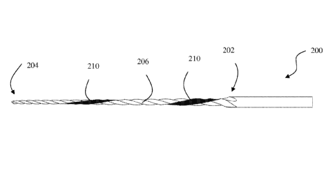
[0031] FIG. 1 is a perspective view of a prior art endodontic
instrument having a
cutting surface and a non-contact area linearly extending along the length of
the instrument.
[0032] FIGS. 2A and 2B are perspective views of an endodontic
instrument having a
cutting surface and a non-contact surface helically extending along the length
of the
instrument according to one embodiment of the present invention.
[0033] FIG. 3A is a plan view of the instrument shown in FIGS. 2A and
2B.
FIGS. 3B and 3C are sectional views taken along the lines B-B and C-C,
respectively, of
FIG 3A.
[0034] FIG. 4 is another plan view of the instrument shown in FIGS. 2A
and 2B.
[0035] FIG. 5 is a plan view an endodontic instrument having a cutting
surface and an
interrupted non-contact surface helically extending along the length of the
instrument
according to another embodiment of the present invention.
[0036] FIG. 6 is a perspective view of an endodontic instrument having
two non-
contact surfaces helically extending in parallel along the length of the
instrument according to
another embodiment of the present invention.
[0037] FIG. 7A is a plan view of the instrument shown in FIG. 6. FIGS.
7B and 7C
are sectional views taken along the lines B-B and C-C, respectively, of FIG
7A.
[0038] FIG. 8 is a chart showing the results of a design study.
[0039] FIG. 9 is a chart showing the results of a torsion study.
268097 00142/106933206 1 - 8c -
CA 3017585 2020-01-20
CA 03017585 2018-09-12
WO 2017/160501
PCT/US2017/020097
DETAILED DESCRIPTION
[0040] An
endodontic instrument 200 according to one embodiment of the present
invention is shown in FIGS. 2A, 2B, 3A-3C, and 4. Instrument 200 has a body
with a cutting
portion that tapers down from an upper end 202 to a pointed lower end 204.
Pointed lower
end 204 can have a cutting tip or a non-cutting tip. In other embodiments,
lower end 204 can
be rounded. Upper and lower ends 202, 204 are spaced apart along a central
axis of the body
such that the cutting portion has a length defined along the axis between
upper and lower
ends 202, 204. Along the cutting portion of the body, instrument 200 has a
cross section in a
plane perpendicular to the axis of the body that has a non-circular
circumference, which is
shown more clearly in FIGS. 3B and 3C.
[0041] The cutting
portion includes a cutting surface 206 extending helically along
the cutting length of instrument 200. Cutting blades 208 extend helically
along cutting
surface 206 and from an inner diameter 212 to an outer diameter 214, as shown
in FIGS. 3B
and 3C. Cutting surface 206 extends about a first portion of the non-circular
circumference
of the cutting portion. Cutting surface 206 extends helically along the axis
of instrument 200
in a first direction, shown in FIGS. 2A and 2B as a -left handed" helical
twist, while cutting
blades 208 extend helically along instrument 200 in an opposite second
direction, shown in
FIGS. 2A and 2B as a "right handed" helical twist. In other embodiments,
cutting blades can
extend helically along the instrument in the same first direction as the
cutting surface.
[0042] The cutting
surface further includes a non-contact surface 210 extending
helically in the first direction along the length of instrument 200. Non-
contact surface 210
forms a linear segment that extends about a second portion of the non-circular
circumference
and is tangential to inner diameter 212 of cutting blades 208. Non-contact
surface 210 is
uninterrupted along the length of the cutting portion in that it extends
continuously from
upper end 202 to lower end 204, as shown in FIG. 4. Non-contact surface 210
can have a
taper corresponding to a taper of the cutting portion. Where the cutting
portion extends all
the way to pointed lower end 204, non-contact surface 210 can extend helically
to the axis of
the cutting portion. Together, cutting surface 206 and non-contact surface 210
make up the
entire outer surface of instrument 200 to allow for the highly efficient
shaping of the root
canal while simultaneously removing debris.
[0043] In other
embodiments, the non-contact surface can be interrupted. For
example, FIG. 5 shows an instrument 1200 similar in many respects to
instrument 200. The
cutting surface of instrument 1200 includes a non-contact surface 1210
extending helically in
the first direction along the length of instrument 1200. Different from that
of instrument 200,
-9-
CA 03017585 2018-09-12
WO 2017/160501
PCT/US2017/020097
non-contact surface 1210 is interrupted along the length of the cutting
portion in that it
extends in segments from upper end 1202 to lower end 1204, as shown in FIG. 5.
These
segments can he separated by the space between adjacent cutting blades 1208 of
cutting
surface 1206.
100441 The
introduction of a helical array of cutting and non-cutting edges allows for
the rapid shaping and cleaning of root canals while evenly disbursing
torsional stresses
ensuring far less breakage and instrument failure. The helical design of
cutting surface 206
and non-contact surface 210 allows for 360 degrees of engagement of instrument
200 with
the tooth when used by rotating or propagating instrument 200. In this way,
every cross
section of the cutting portion along the axis between upper and lower ends
202, 204 in a
plane perpendicular to the axis has a non-circular circumference. The present
endodontic
instruments provide a reduction of stress during removal of dentin without
compromising the
cleansing of the root canal. The incorporation of a non-circular cross-section
reduces stress
and provides for a location for debris to collect away from cutting areas.
[0045] As
indicated above, the non-circular cross-section may be comprised of one
generally circular portion truncated by one flat area that is linear in cross-
section. That is, the
first portion of the non-circular circumference having cutting surface 206 is
generally circular
such that the non-circular circumference is D-shaped. The non-circular cross
section, taken
in a plane perpendicular to a length of the instrument, can be defined by a
perimeter having
an arc-shaped portion connected at each end to the ends of a linear portion.
While cutting
surface 206 extends around the circumference or perimeter of instrument 200 in
a generally
circular manner, the edge of instrument 200 is not arc shaped itself as shown
in the cross
sectional views of FIGS. 3B and 3C. The geometry of the edge is accounted for
by the
configuration of cutting blades 208 of cutting surface 206.
100461 In a
preferred embodiment, the endodontic instrument of the present invention
provides for a cutting surface or face that is generally circular in cross-
section or arc-shaped
and extends about a portion of the circumference of the instrument, but is
interrupted, at one
circumferential location of the instrument, by a non-contact surface or face,
which helically
extends along the cutting length. The instrument can have more than one non-
contact surface
or area and/or more than one cutting surface, as described below.
[0047] A method of
making an instrument described herein, such as instrument 200,
involves first obtaining a substrate that has upper and lower ends spaced
apart along its axis
and an outer surface that tapers from the upper end to the lower end. A cross
section of the
substrate in a plane perpendicular to the axis has a perimeter defined by a
plurality of linear
-10-
CA 03017585 2018-09-12
WO 2017/160501
PCT/US2017/020097
segments and comers formed between adjacent segments. That is, the perimeter
can be
square shaped, triangular, or anther polygonal cross sectional shape. This
type of perimeter
can be seen in FIGS. 3B and 3C. The substrate is configured such that the
Cross sectional
perimeter does not rotate along the axis. In other words, the substrate is
shaped like a
pyramid having substantially axial cutting blades extending generally parallel
to its axis that
are defined by the corners of the perimeter. Obtaining such a substrate can
include
manufacturing or otherwise acquiring the substrate, which is made of metal
such as stainless
steel, nickel titanium, or other materials as described herein.
[0048] The
substrate is then heated and twisted so that the substantially axial cutting
blades are transformed into helical cutting blades. This includes twisting one
of the upper
and lower ends with respect to the other to form a cutting surface along a
cutting portion of
the substrate. At this stage, the cutting surface extends about the entirety
of a circumference
of the substrate in a cross section of the cutting portion in a plane
perpendicular to the axis.
The substrate can be twisted so that one end completes sixteen revolutions
about the axis.
Other configurations are possible, such as those that twist between five and
thirty revolutions
about the axis.
[0049] At this
point, material is removed from the substrate in a helical path along the
axis to form a non-contact surface. That is, the location at which material is
removed travels
along a helical path such that the cutting surface also extends helically
along the axis. The
removal of material can include grinding, milling, or the like and can result
in the non-contact
surface being located at or beneath a minimum diameter of the cutting surface.
This results
in the circumference of a cross section of the cutting portion being non-
circular. As indicated
above, this creation of the non-contact surface can result in its helical path
extending along
the axis in a first direction, and while the helical cutting blades each
extending along the
cutting surface in a second direction opposite from the first direction.
[0050] In another
method of making an instrument described herein, after the
substrate described above is obtained, material can be removed from the
substrate in a helical
path along the axis to form the non-contact surface. As a result of the
removal step being
carried out earlier in the process, the non-contact surface is adjacent to an
undisturbed surface
of the substrate. Then the substrate can he twisted to form the undisturbed
surface into a
cutting surface along a cutting portion of the substrate such that the cutting
surface and the
non-contact surface both extend helically along the axis. The exact
configuration of the
initial helical path of the non-contact surface will be altered during this
process, which can be
-11-
CA 03017585 2018-09-12
WO 2017/160501
PCT/US2017/020097
accounted for during the step of removing material from the substrate. From
here, other steps
can be carried out as discussed above.
[0051] Another
embodiment of an endodontic instrument 300 is shown in FIGS. 6
and 7A-C. Instrument 300 is similar in nature to instrument 200 but includes
multiple non-
contact surfaces helically extending along the cutting length at a smaller
pitch. In between
the non-contact surfaces are multiple cutting surfaces that also extend along
the cutting
length. Cutting surfaces 306a and 306b each include cutting blades 308
extending helically
along the cutting length of instrument 300 and from an inner diameter 312 to
an outer
diameter 314, as shown in FIGS. 7B and 7C. Cutting surfaces 306a and 306b
extend helically
along the instrument in a first direction, while cutting blades 308 extend
helically along the
instrument in an opposite second direction. Cutting surfaces 306a and 306b
extend about
respective portions of the non-circular circumference of the cutting portion.
Non-contact
surfaces 310a and 310b extend helically in the first direction along the
length of instrument
300, and can extend to the axis of the cutting portion. Non-contact surfaces
310a and 310b
each form linear segments that extend about respective portions of the non-
circular
circumference.
[0052] That is,
the non-circular cross-section of instrument 300 includes two
generally circular portions separated by two linear portions. The non-circular
cross section is
therefore defined by a perimeter having first and second arc-shaped portions,
shown more
clearly in FIGS. 7B and 7C, that are connected through first and second linear
portions. The
two generally curved cutting faces are positioned in a circumferentially
opposing relationship
and along the length of the instrument, and two non-contact surfaces are
positioned between
the cutting faces. The two non-contact surfaces helically extend in parallel
along the length
of the instrument.
[0053]
Importantly, the present invention provides for reduced stress to the tooth
and
to the cutting instrument during the removal of dentin from a root canal by
providing at least
one area of non-contact, i.e. one portion of the instrument does not contact
and does not cut
the dentin material, but is recessed back from the general circular cross-
sectional shape of the
device to reduce stress to the tooth, maintain debris away from the cutting
face of the device
and to reduce instrument failure.
[0054] The
relative size of the cutting surface(s) versus the non-contact surface(s) can
be varied as desired. Some variations between the cutting surface and non-
contact surface can
vary in size, including but not limited to about a 1:1, 2:1, or 4:1 ratio.
These ratios can be of
a length of the generally circular cutting surface(s) of the non-circular
circumference to a
-12-
CA 03017585 2018-09-12
WO 2017/160501
PCT/US2017/020097
length of the linear non-contact surfaces of the non-circular circumference.
The angle and
direction in which the non-contact surface helically extends along the cutting
length can be
varied as desired. That is, the non-contact surface can complete one
revolution around the
instrument in 20 mm, and in another embodiment the non-contact surface can
complete one
revolution around the instrument in 30 mm. The length of the instrument may
vary. In one
embodiment, the length of the instrument can range from 5 mm to 80 mm. In
other
embodiments, the length can range from 5 mm to 60 mm, from 5 mm to 50 mm, and
from
15 mm to 40 mm. In one embodiment, the length of the instrument is 25 mm, and
in another
the length is 40 mm. The diameter of the instrument may also vary. In one
embodiment, the
diameter of the instrument can range from 0.02 mm to 8.0 mm. In other
embodiments, the
diameter can range from 0.02 mm to 6.0 mm, from 0.02 mm to 4.0 mm, and from
0.05 mm to
3.0 mm. In one embodiment, the instrument may taper in a parallel or
symmetrical fashion
from such that the outer diameter decreases in value along the taper by an
amount equal to
0.02 mm to 1.0 mm. For example, for every millimeter of length of the
instrument, the taper
can increase by 0.02 mm. The taper can alternately be variable such that
different segments
along the length of the instrument taper at different angles. The cutting
surface and/or non-
contact surface may include a "right handed" helical twist or "left handed"
helical twist.
[0055] The
endodontic instrument can be used manually or by a powered device. By
extending the non-contact suiface in a helical pattern, the endodontic
instrument will engage
the entire area of the canal wall when used in an up-down pecking or
reciprocating motion. In
one embodiment, the instrument may be used with a "hand piece" in rotation or
reciprocation
or manually. A method of using one of the above-described endodontic
instruments can
include inserting the cutting portion of the instrument at least partially
into a root canal, and
reciprocating the instrument along the axis of the cutting portion to remove
dentin. The
method may further include rotating the instrument about the axis of the
cutting portion.
[0056] The
instrument is designed to engage the tooth structure at every point along
its entire length ensuring both cutting and removal of debris simultaneously.
Additionally, the
instrument is less likely to fracture during use due to the even distribution
of torsional forces
along the length of the instrument.
[0057] The
instrument may be composed of metal, including but not limited to
stainless steel, nickel titanium, inconel, ceramic, carbide, metal alloys of
iron, nickel,
titanium, tungsten, copper, niobium, hafnium, aluminum, brass, bronze,
galvanized steel,
high carbon steel, and alloys and combinations of these materials. The
instrument may also
be composed of plastic, resin. and/or ceramic.
-13-
CA 03017585 2018-09-12
WO 2017/160501
PCT/US2017/020097
[0058] A kit can
be provided that includes two or more endodontic instruments as
described above, each having a different size or shape. This can provide a
user with multiple
options of instruments during a related procedure.
[0059] Various
embodiments, including those in accordance with the present
invention, were subject to computer-simulated solid-model testing. The
following three
endodontic instruments were tested.
[0060] A First
Conventional Design of a standard conventional reamer does not have
a non-contact surface. Instead, it is a completely round instrument (360
degrees) that only
contains cutting flutes. The First Conventional Design has more mass than the
other two
designs described below because it does not contain a grounded flat, i.e. a
non-contact
surface. The First Conventional Design has a tapered shaft that has been
twisted sixteen turns
to form flutes at the tip of the shaft.
[0061] A Second
Conventional Design is the reamer or instrument shown in FIG. 1,
and has a tapered shaft that has been twisted sixteen turns to form flutes at
the tip of the shaft.
The Second Conventional Design includes a tapered flat, i.e. a non-contact
surface, that is not
helical and that extends the length of the flutes.
[0062] The Novel
Design is as shown in FIG. 2A and includes the new improved
design with the helical flat, i.e. a non-contact surface extending helically
in the first direction
along the length of the instrument. The Novel Design has a tapered shaft that
has been
twisted sixteen turns to form flutes at the tip of the shaft, with a helical
tapered flat ground
the length of the flutes in the opposite direction of the flutes.
[0063] The first
study performed was a design study, in which two static studies and
two fatigue studies were run on all three designs. In each case, the
instrument was fixed by
its handle and a uniform load was applied to the flute zone of the shaft. A
load of 25 g
(0.055 lbs) was loaded on each design until failure. The factor of safety is
based on a
maximum load (45 g or 0.1 lbs) on the instrument while in constant operation
at its -yield" or
breaking point. A safety factor less than one indicates a less than "safe"
condition.
[0064] The results
of the testing are presented in FIG. 8. The Novel Design
performed similarly to The First Conventional Design, though the Novel Design
endured a
greater maximum stress as compared with the First Conventional Design. This is
because of
the helical non-contact surface or ground flat cut in the opposite direction
of the spiral flutes.
The Second Conventional Design is about half the strength of the other two
designs, which is
likely due to the non-helical tapered flat that extends the length of the
flutes. This flat
-14-
CA 03017585 2018-09-12
WO 2017/160501
PCT/US2017/020097
removes half of the material away from the shaft weakening the shaft, in
comparison with the
other tested designs.
[00651 The second
study performed was a torsion study, in which a static torsion
study was run on all three designs. In each case, the instrument was fixed by
the hole in its
handle and a torque load was applied to the flute zone at the end of the
shaft. A torque load
of 0.006251b-in (0.1oz-in) was used as a load on the flute zone until failure.
This study was
run to show the instruments at a failure state to compare which design is the
strongest
torsionally.
[00661 The results
of the testing are presented in FIG. 9. The Novel Design
performed similarly to The First Conventional Design, though the Novel Design
has more
displacement and endured a greater maximum stress as compared with the First
Conventional
Design. This is because of the helical non-contact surface or ground flat cut
in the opposite
direction of the spiral flutes. Again, the Second Conventional Design is about
half the
strength of the other two designs, which is likely due to the non-helical
tapered flat that
extends the length of the flutes.
[00671 In the
design study, the loads were applied to the cutting edge of each tool
design to simulate the cutting force applied at the cutting edge of the tool.
In the torsion
study, the loads were applied to the cutting edge of each tool design to
simulate the torque of
the cutting force applied at the cutting edge of the tool. Both studies showed
the following.
With the Second Conventional Design, a much higher stress level is seen than
with the other
two because the cutting edge runs the full length of the flute without relief
along the cutting
edge. The Novel Design has a higher stress level than the First Conventional
Design because
it has a cutting edge and the First Conventional Design does not have a
cutting edge. The
Novel Design has a much lower stress level than the Second Conventional Design
because
the cutting edge on the Novel Design is helical so there are reliefs along the
edge of the
cutting surface reducing the effective tangential force applied normal to the
spiral flutes.
[00681 Based on
the findings of these studies, the Novel Design is the best tool of the
three designs for cutting. Because the Novel Design has a helical cutting edge
it cuts more
efficiently, pulling cutting debris out of the hole as it cuts. The First
Conventional Design
has no additional cutting edge, and is therefore not as efficient.
[0069] Due to its
helical geometry, the Novel Design has been proven to exhibit
superior performance as compared to the First and Second Conventional Designs
in terms of
cutting efficiency, torsional strength, flexural strength, and debris removal.
Additionally, the
Novel Design proved to be at least as strong as the First Conventional Design
despite having
-15-
CA 03017585 2018-09-12
WO 2017/160501
PCT/US2017/020097
less mass. The First Conventional Design has more mass than the other two
designs because
it does not contain a grounded flat. The simulation showed that because of the
unique and
non-obvious geometry of the Novel Design, it was at least as strong as the
First Conventional
Design while outperforming the latter in terms of cutting efficiency, tooth
engagement, and
debris removal. This is because the forces are evenly distributed along the
length of the
instrument in the Novel Design. The Novel Design also surpassed the Second
Conventional
Design in terms of durability (less breakage), cutting efficiency, and debris
removal because
the cutting edges engage the tooth structure in 360 degrees as well as up and
down. Thus, the
introduction of a helical "flat" or non-contact surface along the length of
the instrument (as in
instruments 200 and 300) is a very significant improvement which was not
obvious by any
means as shown by the computer simulation.
[00701 Although
the invention herein has been described with reference to particular
embodiments, it is to be understood that these embodiments are merely
illustrative of the
principles and applications of the present invention. It is therefore to be
understood that
numerous modifications may be made to the illustrative embodiments and that
other
arrangements may be devised without departing from the spirit and scope of the
present
invention as defined by the appended claims.
DETAILED DESCRIPTION
[0071] The present
invention enjoys wide industrial applicability including, but not
limited to, instruments and methods related to dental and endodontic use.
-16-