Note: Descriptions are shown in the official language in which they were submitted.
A
ORE TAG ASSEMBLY AND SYSTEM
AND METHOD RE SAME
FIELD OF THE INVENTION
[0001] The present invention is an ore tag assembly and a system
including same, and a
method of using the system.
BACKGROUND OF THE INVENTION
[0002] As is well known in the art, attempts have been made to
develop "ore markers"
that include devices, such as RFID tags, that can be used to identify where,
in a mine, a quantity
of ore came from. This information can be used in different ways. For example,
reliable
information regarding the sources of quantities of ore that have been mined
can be used to enable
the mine operator to control the ore feed to the mill to optimize processing
the ore in the mill.
[0003] However, the known ore markers are generally unsatisfactory,
in different ways.
The RFID tag is typically located in a shell that is hard, because it is
intended to withstand the
significant impact pressures to which the shell is subjected as the ore is
moved from a stope or
other location in the mine toward the mill. In general, the known RFID marker
shells have a high
attrition rate, because they are frequently crushed by the ore.
[0004] Typically, antennas are positioned at conveyor belts on which
the ore is moved,
for example, in order to detect the ore markers before the ore reaches the
mill. However, the
RFID tags frequently are not successfully detected by antennas designed to
detect them, because
the RFID tags may be, for example, buried in the ore on a conveyor belt.
SUMMARY OF THE INVENTION
[0005] There is a need for an ore tag and a system and a method of
utilizing same that
overcomes or mitigates one or more of the disadvantages or defects of the
prior art. Such
disadvantages or defects are not necessarily included in those listed above.
1
CA 3017675 2018-09-18
[0006] In its broad aspect, the invention provides an ore tag assembly
including one or
more tubes extending between first and second ends thereof and defining a
cavity between the
first and second ends thereof, a RFID device located in the cavity, and plugs
positioned in the
respective first and second ends of said at least one tube, to retain the RFID
device in the cavity.
BRIEF DESCRIPTION OF THE DRAWINGS
[0007] The invention will be better understood with reference to the
attached drawings in
which:
[0008] Fig. 1 is a longitudinal cross-section of an embodiment of an ore
tag assembly of
the invention;
[0009] Fig. 2 is an exploded view of certain elements of the ore tag
assembly of Fig. 1,
drawn at a smaller scale;
[0010] Fig. 3 is a cross-section of the ore tag assembly of Fig. 1;
[0011] Fig. 4 is a side view showing utilization of the ore tag
assemblies in ore moving
down a chute, drawn at a smaller scale;
[0012] Fig. 5 is top view of the chute of Fig. 4, and the ore and the ore
tag assemblies
moving down the chute; and
[0013] Fig. 6 is a schematic illustration of an embodiment of a system of
the invention.
DETAILED DESCRIPTION
[0014] In the attached drawings, like reference numerals designate
corresponding
elements throughout. Reference is made to Fig. 1 to describe an embodiment of
an ore tag
assembly of the invention indicated generally by the numeral 20. Preferably,
the ore tag assembly
20 includes one or more tubes 28 extending between first and second ends 30,
32 thereof and
defining a cavity 34 therein extending between the first and second ends 30,
32 in which a RFID
device 36 is located, as will be described. Preferably, the ore tag assembly
20 also includes plugs
2
CA 3017675 2018-09-18
4
=
42, 44 that are positioned in the respective first and second ends 30, 32 of
the tube 28, to retain
the RFID device 36 in the cavity.
[0015] In one embodiment, as illustrated in Fig. 1, the ore tag
assembly 20 preferably
includes an outer tube 22 extending between first and second ends 24, 26
thereof in which the
tube 28 is received. The tube 28 is referred to hereinafter as an inner tube
28 for convenience.
[0016] As will also be described, it is also preferred that
sealant 38, 40 is positioned at the
respective first and second ends 30, 32 of the inner tube 28, to at least
partially seal the cavity
34.
[0017] It will be understood that the outer tube 22 and the
inner tube 28 may be made of
any suitable material. Preferably, the outer tube 22 and the inner tube 28 are
made of a material
that is flexible and also generally permits electromagnetic waves at
frequencies of interest to pass
therethrough, i.e., with minimal interference. Those skilled in the art would
be aware of suitable
materials. For example, it has been found that high density polyethylene is
suitable.
[0018] As can be seen in Figs. 1 and 3, the cavity 34 is
partially defined by an inner
surface 45 of the inner tube 28. In one embodiment, the inner surface 45
preferably is generally
circular in cross-section.
[0019] Preferably, the RFID device 36 is any suitable RFID
device. Those skilled in the
art would be aware of suitable RFID devices. In one embodiment, it is
preferred that the RFID
device 36 is a passive RFID device. It is also preferred that the RFID device
includes an inlay
(not shown) and a body portion 46 in which the RFID inlay is located, as is
known in the art The
body portion 46 may be made of any suitable material and may have any suitable
configuration,
however, it is preferred that the body portion 46 is flexible and elongate,
and has opposed first
and second surfaces 48, 50. It will be understood that the thickness of the
body portion 46 is
exaggerated in Figs. 1-3, for clarity of illustration.
[0020] Alternatively, the RFID device 36 may be an active RFID
device. Those skilled in
the art would appreciate that any suitable alternative form of electronic
device may be substituted
for the RFID device 36.
[0021] The ore tag assembly 20 may have any suitable dimensions.
As an example, the
outer tube 22 may be approximately 6.5 inches long, and have an inner diameter
of approximately
0.75 inch. The outer diameter may be approximately 7/8 inch. The inner tube 28
may be
3
CA 3017675 2018-09-18
,
,
approximately 4.25 inches long, and have an outer diameter of approximately
5/8 inch and an
inner diameter of approximately 0.5 inch. The body portion 46 may be
approximately 4 inches
long and about 0.5 inch wide. The body portion 46 may also be about 0.020 inch
thick.
[0022] Preferably, the ore tag assembly 20 has a relatively
small size. It will be
understood that, preferably, the ore tag assemblies 20 are not removed from
the ore before the
ore is processed in the mill. Accordingly, the ore tag assemblies 20 are, in
the mill, considered to
be additional waste material, which ultimately is to be separated from the
mineral or minerals of
interest in the ore, as the ore is processed.
[0023] As can be seen in Figs. 1 and 2, it is preferred that the
cavity 34 is generally not
filled by the RFID device 36. As will be described, it is preferred that the
RFID device 36 is not
secured to the inner wall 45, nor is the RFID device 36 secured to the sealant
38, 40. It is believed
that the position of the RFID device 36, sealed inside the cavity 34 but not
securely attached to
the inner wall 45 or the sealant 38, 40, is one important reason why the ore
tag assembly 20
appears to be able to survive moving from a point of origin in the mine to the
mill without serious
damage to the RFID device 36. Also, because of the size and elongate shape of
the cavity 34
and the size and corresponding elongate shape of the RFID device 36, the RFID
device 36 is
likely to remain positioned in the cavity generally aligned with an
longitudinal axis "Y" (Fig. 1) of
the ore tag assembly 20.
[0024] The cavity 34 is sufficiently large that the inner and
outer tubes 28, 22 could be
subjected to significant bending before the inner surface 45 of the inner tube
28 would push
against the RFID device 36. Accordingly, the relatively large internal cavity
34 is also believed to
be important to the ability of the ore tag assembly 20 to survive significant
impact loading by the
ore without impairing the functioning of the RFID device 36. In addition, even
if the inner and
outer tubes 28, 22 are bent so that the inner surface 45 pushes against the
RFID device 36,
because the RFID device 36 is positioned loosely in the cavity 34, the RFID
device 36 would
move with the inner surface 45 in response to such engagement.
[0025] In one embodiment, the ore tag assembly 20 is assembled,
first, by inserting the
inner tube 28 into the outer tube 22. Preferably, the inner tube 28 fits into
the outer tube 22 in a
friction fit, so that the inner tube 28 is initially held in place in the
outer tube 22 by friction. The
sealant 38 is then positioned on the inner tube 28 at its first end 30. The
sealant may be any
suitable sealant. Preferably, the sealant 38, 40 is a silicone sealant, which
solidifies relatively
4
CA 3017675 2018-09-18
,
,
quickly. Next, the inner tube 28 and the outer tube 22, while held together by
friction, are
positioned at an acute angle to the horizontal, with the first end 30
downward, and the RFID device
36 is located in the cavity 34. As noted above, the RFID device 36 preferably
has an elongate
body portion 46, and it is preferred that the RFID device 36 is positioned in
the cavity 34 so that
it is lying generally flat on, or partly engaged with, the inner surface 45 of
the inner tube 28, with
the body portion 46 extending the entire length thereof, substantially aligned
with the longitudinal
axis "Y". As is also noted above, the RFID device 36 preferably is not secured
to the inner surface
45, but instead is loosely positioned in the cavity 34, and this is believed
to be important in the
survival of the RFID device 36 as the ore tag assembly 20 is moved, along with
the moving ore,
toward the mill.
[0026] Next, the sealant 40 is positioned on the inner tube 28
at its second end 32. Once
the sealant 40 has solidified, the plugs 42, 44 are inserted into the first
and second ends 24, 26
of the outer tube 22. Those skilled in the art would appreciate that the plugs
42, 44 may press
inwardly upon the sealant 38, 40 after the plugs 42, 44 have been inserted.
[0027] The assembly of the ore tag assembly 20 is schematically
illustrated in Fig. 2. It
will be understood that the sealant 38, 40 is omitted from Fig. 2 for clarity
of illustration.
[0028] It will also be understood that the ore tag assembly 20
may be assembled in other
ways. For instance, the ore tag assembly 20 may include only one tube 28, or
it may include
more than the two tubes 22, 28 that are illustrated in Figs. 1-3. As an
example, the process may
commence with positioning the RFID device 36 inside the cavity 34 therein. The
plugs 42, 44
may then be inserted into the ends 30, 32 respectively.
[0029] It will be understood that the ore tag assemblies 20,
once assembled, may be
distributed in any manner that is appropriate in the circumstances. In
general, the ore tag
assemblies 20 are respectively individually identified by radio frequency
identity, and then
distributed at convenient locations (for example, transfer points, and/or
storage locations) that will
enable the originating location of the ore to be associated with a number of
specific ore tag
assemblies 20. In this way, when the ore tag assemblies 20 are subsequently
read, the respective
originating locations of the ore in which the ore tag assemblies 20 are
positioned can be known,
and the user can make appropriate adjustments in the feed to the mill, or to
the processes in the
mill. Those skilled in the art would be aware of suitable adjustments, the
details of which would
vary from one mine and mill to another. For example, if the ore about to enter
the mill is from a
CA 3017675 2018-09-18
location in the mine that is known to have an unusually high percentage of a
valuable mineral,
then the processes in the mill may be adjusted slightly, to optimize the
processing of such ore.
[0030] Those skilled in the art would appreciate that the ore tag
assemblies 20 may also
be used in industries other than mining, to enable the user (not shown) to
optimize processes
based on the originating locations of different materials that are fed to a
processing facility, or to
adjust the feed to the processing facility. Alternatively, the ore tag
assemblies 20 may be used
simply to track the progress of material through a facility, for example, to
identify any unusual
delays in the movement of the material through the facility.
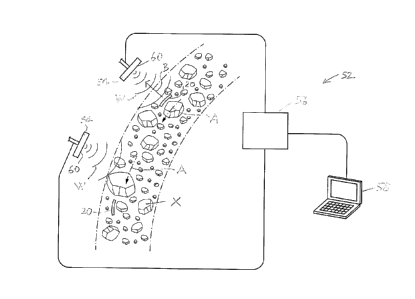
[0031] The invention preferably also includes a system 52 (Fig. 6) in
which the ore
assembly 20 provides the data that may be utilized as described above. In one
embodiment, the
system 52 preferably includes one or more antennas 54 operatively connected
with one or more
RFID readers 56. As schematically illustrated in Fig. 6, the RFID reader 56
preferably is
operatively connected with one or more computers 58, to enable users (not
shown) to analyze
and use the data provided by the RFID devices 36 to take appropriate action.
[0032] Those skilled in the art would appreciate that the data may be
stored and
processed in any suitable manner. For instance, in one embodiment, the data
may be stored
locally on the reader 56. The data may be transferred to the computer via a
network connection
(Fig. 6), or the data transfer may be effected by downloading the data to a
portable storage device
(e.g., a USB stick), and then transferring the data to the computer.
[0033] As is known, the passive RFID devices 36 respond to a signal from
the reader 56,
in the form of a radio wave directed from the antenna 54. The reader 56 sends
electrical energy
to the antenna 54, at which the energy is converted to an electromagnetic wave
that is directed
into the zone through which the RFID devices 36 (i.e., included in the
respective ore tag
assemblies 20) are intended to move. The RFID devices 36 respond to the
initial radio frequency
wave from the antenna with a responding signal back (i.e., backscatter) to the
antenna 54.
Preferably, the antenna 54 includes a surface 60 that is in the form of a
substantially flat element,
and as illustrated, the surface 60 is generally square.
[0034] Those skilled in the art would appreciate that any suitable form
of antenna may be
used. It will be understood that the antennas illustrated include
substantially flat surfaces 60 for
exemplary purposes only.
6
CA 3017675 2018-09-18
[0035] As is known, the radio wave directed from the antenna 54 is
initially generally
directed orthogonally to the surface 60. Similarly, the responding signal
directed back from the
RFID device 36 tends to be directed generally orthogonally to the first
surface 48 of the body
portion 46 of the RFID device 36, or the second surface 50, as the case may
be. It will be
understood that, in order for the strongest signal to be received by the
antenna 54 from the RFID
device 36, the first surface 48 or the second surface 50 of the body portion
46 is substantially
parallel to the surface of the antenna 54.
[0036] Accordingly, it is preferred that the antennas 54 are positioned
for optimal signal
transmission and reception. Those skilled in the art would appreciate that the
positioning of the
antennas 54 relative to the moving stream of the ore "X" in which the ore tag
assemblies 20 are
located is generally approximate, and based on estimated positions of the ore
tag assemblies 20
in the ore "X" as they move past the antennas 54. Also, the configurations of
the antennas would
need to be considered in determining their respective positioning.
[0037] The antennas 54 may be positioned at any suitable locations. Those
skilled in the
art would appreciate that the system 52 may be configured to include any
suitable number of
antennas. For example, the antennas 54 may be located at a conveyor,
positioned so that the
radio waves emitted thereby are receivable by the RFID devices 36 in the ore
tag assemblies 20
that are buried in the ore on the conveyor (Fig. 6). As illustrated in Fig. 6,
the ore "X" may be
moved by a conveyor (not shown), and two antennas 54 are positioned to direct
electromagnetic
waves "W" to the ore tag assemblies 20 that are buried in the ore "X", or
positioned on the ore
"X". The direction of the movement of the ore "X" is indicated by arrows "A".
The two ore tag
assemblies illustrated in Fig. 6 as being located in or on the moving ore "X"
are identified by the
reference numeral 20.
[0038] In use, it has been found that the ore tag assembly 20 generally
tends to survive
the impact loading and other loading on it during movement of the ore, and
accordingly the data
obtained in the system 52 using the ore tag assembly 20 can be very useful. It
is believed that
the high survival rate of the ore tag assembly 20 is due to, among other
things, the flexibility of
the inner tube 28 and the outer tube 22. It is also believed that the ability
of the outer tube 22
and the inner tube 28 to move and bend independently of each other along most
of their lengths
also helps the ore tag assembly 20 survive its movement while embedded in the
ore "X".
7
CA 3017675 2018-09-18
[0039] As noted above, it is also believed that the manner in which the
RFID device 36 is
loosely held inside the cavity 34 is another reason why the ore tag assemblies
20 appear to
successfully survive the journey from a location in the mine to the mill,
mixed in with the moving
ore "X". Because the RFID device 36 is loosely held in the cavity 34, the
bending, squeezing,
and twisting to which the outer and inner tubes 22, 28 are subjected as the
ore is transported
generally does not result in corresponding bending or twisting of the RFID
device 36, at least not
to the same extent.
[0040] It will be understood that Fig. 6 may alternatively be seen as
schematically
illustrating a substantially vertical movement of the ore "X", i.e., a free
fall movement, propelled
by gravity, at a transfer point.
[0041] In Fig. 6, one of the ore tag assemblies 20 is illustrated as
directing backscatter
therefrom (schematically represented by arrow "B") toward the antenna 54
closest to it.
[0042] Those skilled in the art would appreciate that, depending on the
extent to which
the ore tag assemblies 20 are buried in the ore "X", the ore may interfere
with communications
between the antenna 54 and the ore tag assemblies 20. This may happen, for
example, when
the antennas 54 are positioned to identify the ore tag assemblies 20 located
in the ore located on
a conveyor belt. Accordingly, in one embodiment, the antennas 54 preferably
are positioned to
read the ore tag assemblies 20 when the ore (and the ore tag assemblies with
the ore) are in free
fall, due to gravity. Those skilled in the art would also appreciate that such
movement of the ore
may occur at one or more transfer points as the ore is moved from its source
location (e.g., a
stope) in the mine to the mill.
[0043] Examples of how the antennas 54 may be positioned to read the ore
tag
assemblies 20 when the ore in which the ore tag assemblies 20 are located is
vertically moved
by gravity are illustrated in Figs. 4 and 5. In Figs. 4 and 5, the antennas
are identified by reference
characters 54A-54D for convenience. They are positioned above a chute 62 down
which the ore
"X" moves, with the ore tag assemblies 20 being located in the ore. The
direction of movement
of the ore is indicated by arrow "A". At a lip 64 of the chute 62, the ore is
not supported by the
chute 62, and the ore "X" moves generally vertically downward under the
influence of gravity.
[0044] Each of the antennas 54A-54D is energized to direct
electromagnetic waves "W"
therefrom. It is believed that, when the antennas 54 are positioned to locate
the ore tag
8
CA 3017675 2018-09-18
assemblies 20 that are in the ore "X" that is falling, data is obtainable from
all, or substantially all,
of the ore tag assemblies 20 in the falling ore "X".
[0045]
It will be appreciated by those skilled in the art that the invention can take
many
forms, and that such forms are within the scope of the invention as claimed.
The scope of the
claims should not be limited by the preferred embodiments set forth in the
examples, but should
be given the broadest interpretation consistent with the description as a
whole.
9
CA 3017675 2018-09-18