Note: Descriptions are shown in the official language in which they were submitted.
CA 03017702 2018-09-13
WO 1
2017/168359
PCT/IB2017/051819
Title
Fluidic rotor having orientable blades with improved blade control
Field of the Application
The present invention concerns generally fluidic rotors having orientable
blades designed to work in a gaseous or liquid environment, both to generate
mechanical energy and to propel a moving body. These rotors apply particularly
to wind turbines, marine turbines, nautical and aircraft propellers and
turbines
in general.
Background to the invention
Such a fluidic rotor with orientable blades is disclosed specifically by
documents W02014/006603A1 and W02016/067251A1 in the name of the
Applicant.
The blade control structure described in these documents, although
effective for achieving the desired object of oscillation of the blades during
the
rotation of the rotor, stil( leaves a certain degree of complexity.
Summarv of the invention
The invention aims to improve the control structure described in this
document and to introduce at least one of the following advantages: greater
simplicity, greater robustness, greater ease of adjustment, easier
industrialization and better performance at high rotational speeds.
We therefore propose a 1. Rotating machine having a fluidic rotor, the
rotor comprising at least one blade mounted on an arm rotating about a rotor
CA 03017702 2018-09-13
WO 2
2017/168359
PCT/IB2017/051819
shaft forming a main axis of the rotor, the rotor being kept by a supporting
structure in an orientation such that said axis is substantially perpendicular
to
the direction of flow of the fluid, the blade being mou nted so as to pivot
about
an axis of rotation of the blade parallel to the main axis, the machine
comprising
means for generating a relative oscillation movement of the blade with respect
to the arm at the axis of rotation of the blade, in order in this way to vary
the
inclination of the blade during the rotation of the rotor, said means
comprising,
at the arm end, a mechanism comprising a first rotating element known as the
drive element and a second rotating element known as the driven element, the
elements being mounted on mutually parallel axes of rotation and separated by
an inter-axis distance, the orientation of the drive element being controlled
depending on the orientation of the rotor shaft while the orientation of the
driven
element determines the orientation of the blade, one of the rotating elements
comprising a finger spaced apart from its axis of rotation and the other
rotating
element comprising a groove which receives the finger and in which the finger
can slide.
In a preferred but optional manner, this machine features the following
additional characteristics, taken individually or in any combinations that a
person skilled in the art would deem to be technically compatible:
* said groove is straight;
* said groove is not straight;
* the distance between the two ends of the groove is at least equal to
double the inter-axis distance;
* the machine comprises means to adjust the distance between the axes
of rotation of the two elements;
CA 03017702 2018-09-13
WO 3
2017/168359
PCT/IB2017/051819
* the distance between the main axis of rotation of the rotor and the axis
of rotation of the drive element is constant;
* the distance between the main axis of rotation of the rotor and the axis
of rotation of the driven element is constant;
* the distances between the main axis of rotation of the rotor and the
axes of rotation of the drive element and the driven element, respectively,
are
equal, wherein the drive element and the driven element are mounted on
supports capable of being adjusted angularly;
* the angular adjustment is performed about the main axis of the rotor;
* the support for the driven element is formed by the arm of the
associated blade;
* the machine comprises means of disconnection between the rotor shaft
and the driven element;
* disconnection means are provided between the rotor shaft and an
organ that is engaged with the drive element.
Brief description of the drawings
Further aspects, objects and advantages of the present invention will
emerge more clearly from the following detailed description of preferred
embodiments thereof, given by way of non-limiting example and made with
reference to the accompanying drawings, in which:
Figure 1 is a schematic view of a side elevation of a rotor blade having
orientable blades according to the prior art;
Figure 2 shows schematically, in a front exploded view, two elements of
a device to control the orientation of rotor blades according to the
invention;
CA 03017702 2018-09-13
WO 4
2017/168359
PCT/IB2017/051819
Figures 3A and 3B are front and profile schematic views respectively
showing the cooperation of the elements of Figure 2 in a first configuration;
Figures 4A and 4B are front and profile schematic views respectively
showing the cooperation of the elements of Figure 2 in a second configuration;
Figure 5 shows the mutual position of the elements according to the
second configuration in four angular positions;
Figure 6 shows a front view of the incorporation of the control device of
Figures 2 to 5 in a rotor arm with orientable blades;
Figure 7 is a profile view of the assembly of Figure 6;
Figure 8 shows the mutual position of the different parts of the assembly
of Figures 7 and 8 in four angular positions;
Figure 9 gives an example of the angular setting law obtained with the
orientation control device shown in Figures 2 to 8;
Figure 10 shows a schematic front view of a first part of the mechanism
for adjusting the amplitude of the orientation of the blades that can be
implemented in a rotor with orientable blades;
Figure 11 shows a schematic front view of a second part of the
adjustment mechanism;
Figure 12 shows a schematic front view of the two parts of the amplitude
adjustment mechanism in a first mutual position;
Figure 13 shown a schematic front view of the two parts of the amplitude
adjustment mechanism in a second mutual position, and
Figure 14 shows schematically an example of a mechanism for the
disconnection of the blade-orientation control.
CA 03017702 2018-09-13
WO 5
2017/168359
PCT/I132017/051819
Detailed description of preferred embodiments
Throughout the present description, reference shah l be made to the rotor
as described in application W02014/006603A1, the contents of which shah l be
deemed to form part of the present description. The contents of application
W02016/067251A1 in the name of the Applicant shall also be deemed to form
part of the present description.
With reference firstly to Figure 1, from the perspective of plane PL of a
rotor blade P (in relation to the direction F of the flow of gas or liquid),
the
movement is an oscillating movement about a point of rotation PR located on
the blade.
The basic elements implemented in the present invention are shown in
Figure 2: two elements A and B are driven one by the other while turning about
two parallel axes. Element A is provided with a groove or slot C made in one
of
its radiuses. Element B is provided with a finger D, spaced apart by a
distance
x from the center of the disk. The finger D is provided to be able to slide in
the
groove or slot C of the disk A. It will be noted that the groove or slot C
passes
or does flot pass fully through and has a form that is straight or flot
straight,
depending on the kinematics desired to be produced.
It will be noted here that the diameters and even the shape of the
elements A and B have no impact here, the only significant factors being the
position of the finger D in relation to its own axis of rotation and the
geometry
of the slot C in relation to its own axis of rotation.
In Figures 3A and 3B, the axes of elements A and B are combined. One
drives the other (and vice versa) in phase, i.e. with no angular misalignment
between the two elements during their rotation.
CA 03017702 2018-09-13
WO 6
2017/168359
PCT/1132017/051819
In Figures 4A and 4B, the axes of elements A and B are flot combined
(but are parallel to one another). In this case, element A drives element B
(or
vice versa), with the creation of an alternating angular misalignment between
the two elements during rotation.
It will be noted that in order for the assembly formed of elements A and
B to be able to operate, the travel length of the finger D in the groove C
must
be able to be double the distance DA of misalignment between the axes of
elements A and B, which dictates the length of the groove C in order for it to
afford this possibility. Moreover, the groove C must be wide enough to provide
sufficient clearance for the finger D to move inside said groove while
limiting
friction. In this respect, the finger D must be advantageously provided with a
bail bearing to ensure smooth sliding between the finger D and the walls of
the
groove C. These walls can moreover be made of a special wear-resistant
material (surface treatment, chromium plating, etc.). As a variation, to
promote
groove/finger cooperation, a bail guide, bail sleeve, slider, etc. can be
provided.
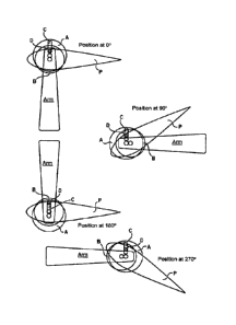
Figure 5 shows the kinematics obtained with a straight groove and, in
particular, the setting law generated for four angular positions. Here,
element A
is regarded as being provided with the groove C as the angular reference and
it is assumed that element A is driving element B, turning in a clockwise
direction in Figure 5 (the opposite reasoning leads to the same result, to the
nearby setting sign). The setting law can be summarized as follows:
- position 0 : no angular misalignment;
- position at 90 : element B lags behind by -x in relation to element A;
- position at 180 : no angular misalignment;
- position at 270 : element B is ahead by +x in relation to element A.
CA 03017702 2018-09-13
WO 7
2017/168359
PCT/1132017/051819
It is understood that, by adjusting the different parameters of the
geometry such as the position, the shape and the dimensions of the groove C,
the position of the finger D in relation to the axis of the disk B and the
distance
DA between the axes of rotation of the two disks, an infinite number of
different
setting laws can be obtained. Variations in the setting laws can also be
obtained
by choosing to perform the drive either by the element bearing the slot or
groove, or by the element bearing the finger.
The setting laws produced can thus vary over a wide range, covering in
particular sinusoidal type laws and trochoidal type laws.
By way of example, if a distance DA is chosen of 30mm between the
axes and 50mm for the position of the finger D in relation to the center of
rotation
of the disk B, the amplitude of the angular misalignment x is on the order of
36 .
The incorporation of the mechanism into a rotor of the general type
described in W02014/006603A1 will now be described.
In this document, the angular position of the nacelle during the rotation
of the rotor is assured by means of a belt (or a chain, or angle gears, or
pinions)
engaging around a pulley located on the main axis of rotation of the rotor, a
pulley that is strictly speaking fixed (but capable of being controlled in
energy-
recovery mode in order to ensure the position of the blades in relation to the
direction of flow, or in propeller mode in order to direct the flow
generated).
In the present invention, according to a first embodiment, this
mechanical connection drives the element A provided with the groove C
(according to a second embodiment of the invention, this could be element B
provided with the finger D).
CA 03017702 2018-09-13
WO 8
2017/168359
PCT/IB2017/051819
The blade P that is to be controlled is directly or indirectly connected to
the element B provided with the finger D. Thus the nacelle, crankshaft,
connecting rod, gearing and linkage assembly of the rotor described in
document W02014/006603A1 is eliminated.
Figures 6 and 7 show this first embodiment: a belt CR drives element A,
here disk-shaped, and the blade P is rotationally fixed with element 6, here
also
disk-shaped. Here the groove C is straight.
is assumed here that the rotor is turning in an anti-clockwise direction
(i.e. in recovery mode, the motive flow, gaseous or liquid, coming from the
left).
Four positions, spaced apart from one another by 900, are shown in Figure 8.
An orientation effect of the blade P similar to that described in
W02014/006603A1 is achieved. Of course, the mechanism formed by
elements A and B and the driving means of element A are reproduced in as
many numbers as there are blades P on the rotor.
The great simplicity and great strength of the mechanical solution of the
present invention is easy to see from figures 6 to 8.
We will now explain the mathematical law of angular displacement of
element B in relation to element A (in the case of a straight and rectilinear
groove).
Where:
R is the distance of the finger D in relation to the axis of rotation of
element B,
D is the distance between the axes of rotation of elements A and B,
x = R/D,
a is the angle of disk A in relation to the reference direction Ox,
CA 03017702 2018-09-13
WO 9
2017/168359
PCT/032017/051819
8 is the angle of disk B in relation to the reference direction Ox.
It will be understood that if the misalignment D between the axes of
rotation of the two disks is zero, then no angular misalignment will appear
between the disks during rotation; in the case of a rotor with N blades, the
blades would in this case be parallel to one another. This can have an impact
when stopping the rotor.
The angular misalignment between element B and element A during the
rotation of the disks is very close to a sinusoidal law of which the amplitude
is
directly proportional to the value x, according to the following equation:
cos(e)=.2(c)-1+cos(a)Vcos2(a)-14-x2
x
The graph in Figure 9 shows the setting law of a blade identified in
relation to the direction of flow (let us imagine for convenience a wind
turbine
application) with D=14mm, R=25.2mm, where x = 1.8.
It will be observed that the law is very close to a sinusoidal law with an
amplitude here of 33.750.
We will now discuss the incorporation of the elements into the rotor and
the way in which the setting law can be adjusted.
Although the position of the finger D is set by construction (even if
according to one embodiment, the value R could be variable), it will be
.. understood that it is advantageous to be able to control the distance D
between
the two elements A and B so as to be able to adjust the setting law according
to the application and the operating speed of the rotor.
CA 03017702 2018-09-13
WO 10
2017/168359
PCT/1B2017/051819
By way of example, when the rotor is operating in wind turbine mode, it
is practical to be able to lower the aerodynamic efficiency Cp as the wind
increases.
In propeller mode, it may be desirable to be able to vary the setting law
depending on whether operation is at low or high speed.
Figures 6 to 8 show that the respective axes of disks A and B are on the
same radius of the rotor that carnes them. More precisely, it will be observed
that the axis of rotation of disk A is further away from the axis of rotation
of the
rotor than the axis of rotation of disk B (but this could be the opposite:
axis of
disk A closer to the axis of the rotor than the axis of disk B).
In order to vary the amplitude setting law, it has been explained above
that we could simply vary the distance between the axes of rotation of the two
disks. According to this first embodiment where the two disks have their axis
of
rotation on the same radius of the rotor that cardes them, several solutions
can
be envisaged:
- either the position of the axis of rotation of disk B and therefore the
blade is changed, which, however, could present a certain technical complexity
as regards control,
- or the position of the axis of rotation of disk A is changed; which, in this
case could also be complex; in fact, if this disk is driven by a belt (or a
chain)
the belt must be kept under tension while controlling the synchronism between
the disk and the groove and the central pulley; and in the case of control by
900
angle gears, it is possible to use grooved axes to enable the control to
slide,
but here too technically there may be a certain level of complexity;
CA 03017702 2018-09-13
WO 11
2017/168359
PCT/162017/051819
- or even the axis of rotation of disk A is positioned at a distance r from
the center of the rotor, the axis of rotation of disk B is positioned at the
same
distance r, and the two disks are mounted on two respective plates that can be
angularly nnisaligned; thus in order to change the distance D, we need simply
to angularly misalign (in relation to the main axis of rotation of the rotor)
the
plates supporting the two disks; one advantage is that according to this mode,
the distance r is fixed, and so the inter-axis between the axis of rotation of
each
of disks A and B and the center of the rotor remains fixed; this makes it
possible
to eliminate the problems of variable tensions or geometries of the drives by
belts, chains or gears (gear train or 900 angle gears), and to keep a fixed
distance between the axes of the blades and the axis of the rotor.
Figures 10 to 13 show an implementation of this third possibility, with a
belt drive, for one blade. Figure 10 shows a plate P1 supporting the disk A
provided with its groove C, this disk A forming a pulley driven by the belt
CR.
The belt CR, mounted on a fixed pulley centered on the axis of the rotor and
of
the same diameter as the pulley A, keeps the latter in a constant absolute
orientation during the rotation of the rotor.
Figure 11 shows a plate P2 supporting the element B bearing the finger
D, this element B driving the blade P.
In Figure 12, the plates occupy positions such that there is no angular
misalignment between them: the distance DA (distance between the axes of
rotation of elements A and B) is zero, and so no angular misalignment is
created
between the two elements A and B during the rotation of the rotor.
In Figure 13, the plates P1 and P2 have been displaced in relation to
one another to create an angular misalignment 0 between them; the distance
CA 03017702 2018-09-13
WO 12
2017/168359
PCT/IB2017/051819
DA is therefore flot zero and the rotation of the rotor creates an angular
misalignment between the two elements A and B during the rotation of the
rotor,
so as to change the orientation of the blade P correspondingly.
The adjustment of the mutual angular position of the two plates therefore
results in a change of the setting law.
In a basic embodiment, this adjustment can be made statically when
assembling the rotor: for example, plate P1 is provided with oblong holes
allowing the angular misalignment to be adjusted once and for ail, depending
on the conditions and constraints of the desired application.
In certain applications, an active adjustment is required, where a control
device is capable of adjusting, in real time or at least with an appropriate
responsiveness, the angular misalignment between the two plates P1 and P2
to have the best setting law of the given operating conditions.
ln one embodiment, electric actuators fitted directly onto the plates can
be used, which involves introducing an electric control from the rotor support
by
means of rotating collectors. A wirelessly controlled system could also be
provided to directly control the actuators, it being possible to power the
latter
either by small generators driven for example by belts and associated organs
(or chains, angle gears, etc.), or by a photovoltaic device.
A preferred solution is, however, to create a purely mechanical control
from the center of the rotor up to each plate P1 or P2 in order to ensure its
adjustment. An architecture to achieve this could involve a sliding axis
(translation) inside the main axis of rotation of the rotor, said axis being
driven
in translation either by an actuator (electrical, hydraulic, etc.) controlled
electronically, or by a purely mechanical system of the Watts regulator type.
CA 03017702 2018-09-13
WO 13
2017/168359
PCT/IB2017/051819
The other end of this control axis could be connected to a swashplate mounted
on a bearing (the control axis does flot turn with the rotor, whereas the
swashplate does turn with the rotor). Clevises, bail joints and gears could
emanate from this swashplate allowing the position of each element A in
relation to each associated element B to be controlled.
We will now describe another solution to perform the adjustment of the
distance DA between the axes of rotation of the elements A and B. According
to this solution, the disk A provided with the groove C is kept with a fixed
angular
orientation in relation to the central pulley of the rotor and is mounted on a
guide
enabling it to slide along the rotor arm so as to reduce or increase the
distance
DA between the axes of rotation of the elements A and B, via a control brought
to the center of the rotor or by means of appropriate actuators.
Since the chains or belts cannot as such cope with this variation of
distance, one solution that enables this adjustment to be made is a
transmission
system with an angle gear transmission with a grooved axis.
It is, however, possible to adopt a belt or chain solution with a servo
tensioning system.
In the specific case of a wind turbine application, a machine according
to the invention advantageously comprises a safety device to reduce its
aerodynamic efficiency to zero so as to be able to cope with storm conditions,
or even to carry out maintenance work. One approach towards implementing
this security feature involves releasing the servomechanisms of the blades so
that they become free on their respective axis and behave like weather vanes,
thus canceling out the torque that they could exert on the rotor. Another
object
CA 03017702 2018-09-13
WO 14
2017/168359
PCT/IB2017/051819
is to be able simply to switch the control system back on without the need to
readjust the blade setting law.
The release of the blade mechanisms is ensured by releasing the pulleys
that are arranged on the axis of the rotor and drive the belts (or the pinions
that
drive the chains). With reference to Figure 14, this can be achieved by
ensuring
that a pulley or pinion P driving a belt or a chain has a groove G1, while the
central shaft AC of the rotor is provided with a groove G2. The reference CL
indicates a key capable of sliding along the axis AC in the groove formed
jointly
by grooves G1 and G2, both by the groove of the axis and by the groove of the
pulley.
The release of the key CL can be achieved by an electronic control unit
is response to signais from sensors, or by using a mechanical system released
when the rotation of the rotor reaches a certain speed, for example a system
using Watts pendulum type centrifugai force, associated with a trigger
enabling
the key to be released.
Clearly, the present invention is in no way limited to the embodiments
described above and represented in the drawings, but a person skilled in the
art would know how to apply numerous variations and modifications thereto. In
particular:
- torque limiters (for example with bail bearings) could be placed on the
kinematic chain so as to ensure the integrity of the rotor in the event of use
beyond set limits (for example in the event of a storm for a wind turbine);
these
torque limiters could, in one embodiment, be fitted between each blade and the
element B that drives it;
CA 03017702 2018-09-13
WO 15
2017/168359
PCT/032017/051819
- each blade could be driven flot by element B bearing the finger D, but
by element A bearing the groove or slot C, element B then being driven by the
belt, chain or other means of transmission from the center of the rotor. This
results in a setting law that is the inverse function of that achieved when
the
blade is driven by element B and that can be preferable in certain cases.
Moreover, the mechanisms for adjusting the amplitude of the oscillation
of the blades (i.e. of value x referred to above) can be applied by a person
skilled in the art to the blade control systems referred to in documents
W02014/006603A1 and W02016/067251A1.
As stated, the invention applies to the field of wind or marine turbines as
well as to nautical and aircraft propellers. It also applies to the production
of
turbines, in which case a fairing is provided around the rotor to guide the
flow.
In this case, a generally uniform flow is obtained across the entire section
swept
by the rotor, unlike the case of the majority of conventional turbines.