Note: Descriptions are shown in the official language in which they were submitted.
UNMANNED MARINE VESSEL FOR SEISMIC SOURCES
BACKGROUND
[0001]This disclosure relates to seismic surveys and seismic sources,
including
marine-based seismic source deployment. More generally, the disclosure
encompasses deployment and retrieval technologies for marine-based seismic
source systems, including, but not limited to, towed air gun arrays.
[0002]Traditional marine seismic surveys typically utilize a number of seismic
source and receivers systems towed behind a seismic survey vessel, for example
in the form of an air gun array and a towed seismic streamer array.
Alternatively,
a combination of seismic sources can be employed with one or more ocean bottom
cables or autonomous node systems.
[0003]Seismic exploration techniques include controlling the emission of
seismic
energy directed into the Earth with a seismic source (e.g., dynamite, air
guns,
vibrators, etc.), and monitoring the Earth's response to the seismic energy
with
one or more nodes or receivers configured to detect reflected seismic waves,
in
order to create an image of the subsurface. In operation of a typical seismic
survey, the air guns or other sources are used to generate seismic energy in
the
form of acoustic waves, which propagates down through the water column,
penetrates the ocean floor or other bottom surface, and is reflected from the
underlying subsurface structures. The reflected energy travels back up to the
seismic streamers, nodes, or other seismic receivers, where it is detected by
hydrophones, geophones and similar seismic sensor devices configured to
generate seismic data responsive to the seismic waveforms. Scientists and
engineers can then conduct seismic surveys based on the acquired sensor data,
e.g., utilizing seismic inversion and other wave exploration techniques, in
order to
identify and map oil and gas reservoirs, salt and rock formations, and other
subsurface structures of interest.
[0004]Conventional marine seismic surveys generally involve towing one or more
seismic sources behind a seismic vessel, along with an array of seismic
receivers
or nodes. The seismic nodes can deployed along one or more ocean bottom
cables, in the form of autonomous nodes disposed on the seabed, or deployed at
a particular depth and orientation within the water column. Each receiver or
node
can include a number of different pressure and/or particle motion sensors in
¨1¨
Date Recue/Date Received 2023-07-28
proximity to one another, for example using a hydrophone system that records
scalar pressure measurements of the seismic wavefield and a geophone array
that records three-dimensional vector velocity measurements of the
corresponding particle motion. Geophysical data pertaining to the wavefield
can
then be acquired by observing the reflected seismic signals, and the signals
can
be processed to form an image indicating the composition and subsurface
structure of the Earth near the survey location, as described above.
[0005] Deploying, towing and retrieving the seismic sources are complex tasks,
limiting the number of conventional source configurations that can be used in
a
given survey area. As more air guns or other sources are added to the array,
the
associated high-pressure pneumatic connections and umbilical cabling also get
longer and larger in diameter, increasing drag, turbulence and vibrational
effects.
Increased drag consumes more fuel and can slow the tow vessel, substantially
raising operational costs. As a result, there is a need for a more flexible
approach
to source towing and seismic source array deployment, which is not subject to
all
the same limitations of the prior art.
SUMMARY
[0006]An unmanned marine vessel system comprises a hull with one or more hull
components configured to provide buoyancy in a water column or other body of
water, a seismic source configured to generate seismic energy, and a
deployment
system or apparatus configured to deploy the seismic source from the unmanned
vessel into the body of water.
[0007]The buoyancy can be negative, positive or neutral. The seismic energy
can
propagate through the body of water and reflects from subsurface structures,
allowing a seismic image of the corresponding geological features to be
generated.
[0008]The unmanned marine vessel can be configured for generating
compressed air for the seismic source (e.g., an air gun subarray), using an on-
board air compressor. A source line can provide the compressed air to the
seismic
source, without requiring other external pneumatic connections to the unmanned
vessel (e.g., without pneumatic or umbilical contention to a tow ship or other
external source).
[0009]Suitable embodiments of an unmanned or autonomous marine vessel may
include a hull configured to provide buoyancy, a seismic source configured to
¨2¨
Date Recue/Date Received 2023-07-28
generate seismic energy, a deployment system configured to deploy the seismic
source from the unmanned vessel into a body of water, and a compressor
configured for generating compressed air. A source line provides the
compressed
air from the compressor to the seismic source, and the seismic energy
generated
.. by the source propagates through the body of water.
[0010]A seismic source array can be configured to include one or more of such
unmanned or autonomous vessels, each providing buoyancy in the surrounding
water column. The buoyancy can be positive, negative or neutral.
[0011]One or more seismic sources can be deployed into the water column from
each of the unmanned vessels, e.g., with a source line providing compressed
air
to the respective seismic sources. The seismic sources can be configured to
generate seismic energy from the compressed air. The seismic energy can
propagate through the water column and beneath the seafloor or ocean bed to
generate a reflected wavefield. The reflected wavefield can be sampled by an
array of seismic receivers or nodes to generate acquired seismic data, which
can
be processed in order to generate images of subsurface reservoirs and other
geological structures of interest, in or near the seismic survey location.
[0012] Marine seismic survey system embodiments can include a tow ship or
other
marine vessel having a back deck area, with a docking station configured for
deploying a plurality of unmanned or autonomous marine vessels into a body of
water. Each of the unmanned or autonomous marine vessels can include a hull
configured to provide buoyancy, a seismic source configured to generate
seismic
energy, and a deployment system configured to deploy the seismic source into
an
adjacent water column.
[0013]A source line can be configured to provide compressed air from the
unmanned vessel to the seismic source(s), in order to generate seismic energy
that propagates through the water column. Alternatively, one or more of the
unmanned marine vessels can provide another seismic component configured for
a seismic survey, e.g., a streamer or node, either independently or in
combination
with a seismic source. The deployment system is configured to deploy the
seismic
components into the water column, in order to perform the survey.
BRIEF DESCRIPTION OF THE DRAWINGS
[0014]FIG. 1 is a schematic view of a towed seismic source array utilizing one
or
more unmanned source vessels (UMSVs).
¨3¨
Date Recue/Date Received 2023-07-28
[0015]FIG. 2 is an alternate view of the seismic source array, with a paired
source
configuration.
[0016]FIG. 3 is a tow diagram for the seismic source array in FIG. 2,
illustrating
the non-uniform lateral source spacing.
[0017]FIG. 4A is a detail view of the seismic source array in FIG. 2, showing
the
deflector, trolley cable and tow bridle configuration.
[0018] FIG. 4B is another detail view of the seismic source array in FIG. 2,
showing
the back deck configuration of the tow vessel.
[0019]FIG. 4C is a further detail view of the seismic source array in FIG. 2,
showing the paired air gun subarray configuration.
[0020]FIG. 5 is an isometric view of an unmanned or autonomous source vessel.
[0021]FIG. 6A is a side section view of the unmanned vessel in FIG. 5, showing
the centerline profile.
[0022]FIG. 6B is a rear view of the unmanned vessel in FIG. 5, showing the
deployment system and winch.
[0023]FIG. 7 is an isometric view of an unmanned or autonomous source vessel
with a slipway-based system for deployment and retrieval of an air gun
subarray.
[0024]FIG. 8A is a top plan view of the unmanned vessel in FIG. 7, showing the
slipway and roller configuration.
[0025]FIG. 8B is a side section view of the unmanned vessel in FIG. 7, showing
the centerline profile.
[0026]FIG. 8C is a side elevation view of the unmanned vessel in FIG. 7,
showing
the outboard profile.
[0027]FIG. 9A is a midship section view of the unmanned vessel in FIG. 7,
showing the slipway configuration.
[0028]FIG. 9B is an aft section view of the unmanned vessel in FIG. 7, showing
the roller configuration.
[0029]FIG. 9C is a section view of an aft roller for the unmanned vessel in
FIG. 7.
[0030]FIG. 10A is a top plan view of an unmanned or autonomous source vessel
with a twin-hull configuration.
[0031]FIG. 10B is a perspective view of an alternate twin-hulled configuration
for
the unmanned vessel in FIG. 10A.
[0032]FIG. 11A is an end view of a docking station for deploying and
retrieving
unmanned or autonomous marine vessels.
¨4¨
Date Recue/Date Received 2023-07-28
[0033]FIG. 11B is a top plan view of the docking station, showing the
individual
docking bays.
[0034]FIG. 11C is a perspective view of the docking station in FIGS. 11A and
11B.
[0036]FIG. 11D is a side elevation view of the docking station, illustrating
operation of the gantry crane.
[0036]FIG. 12 is a block diagram of a control system configured for operation
of
an unmanned or autonomous marine vessel.
[0037]FIG. 13 is a block diagram of a method for operating one or more
unmanned or autonomous source vessels to perform a marine seismic survey.
[0038]FIG. 14A is an isometric view of a docking apparatus with a hinged ramp
and slipway system for unmanned or autonomous source vessels.
[0039]FIG. 14B is a profile view of the ramp and slipway system, in a deployed
configuration.
[0040]FIG. 15A is a plan view of the deployed ramp and slipway system.
[0041]FIG. 15B is an aft view of the deployed ramp and slipway system.
[0042]FIG. 16A is an isometric view of the ramp and slipway system, in a
raised
or stowed position.
[0043]FIG. 16B is a profile view of the stowed ramp and slipway system.
[0044]FIG. 17A is a plan view of the ramp and slipway system, in the raised or
stowed position.
[0045] FIG. 17B is an aft view of the stowed ramp and slipway system, showing
a
representative gantry crane arrangement.
[0046]FIG. 17C is a detail view of the gantry crane.
[0047]FIG. 18A is an isometric view illustrating unmanned or autonomous source
vessel deployment on a ramp and slipway system.
[0048] FIG. 18B is an aft view illustrating the source vessel deployment
procedure.
[0049]FIG. 18C is a section view illustrating the source vessel during
deployment.
[0050] FIG. 19A is an elevation view illustrating source vessel retrieval on a
ramp
and slipway system.
[0061]FIG. 19B is a plan view illustrating the source vessel retrieval
procedure.
[0062]FIG. 19C is an isometric view of a carriage apparatus for deploying and
retrieving an unmanned or autonomous source vessel.
¨5¨
Date Recue/Date Received 2023-07-28
DETAILED DESCRIPTION
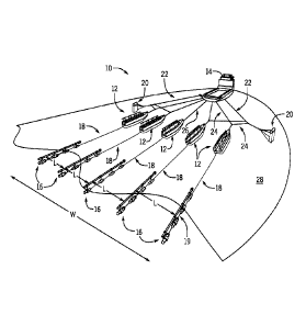
[0053] FIG. 1 is a schematic view of an exemplary towed seismic source array
10,
utilizing one or more unmanned source vessels (UMSVs) 12. Unmanned source
vessels 12 are deployed behind a tow vessel or other seismic ship 14. Air gun
subarrays 16 (or other seismic source components) are deployed from unmanned
source vessels 12, and connected via source lines 18.
[0064]As shown in FIG. 1, paravanes, deflectors, or similar diverter or door
systems 20 are deployed to spread unmanned source vessels 12 out behind
seismic ship 14. A combination of wide deflector ropes 22, trolley ropes 24,
and
individual tow ropes 26 can be used to provide the desired overall source
width
W. Additional trolley ropes or other cross members 24 can be provided to
maintain
desired spacing L between individual unmanned source vessels 12, and the
associated air gun subarrays or seismic sources 16.
[0066]In one particular example, annular port air gun clusters or similar
source
components 16 can be distributed coaxially along the source line, but this is
merely
one example, and other configurations are also suitable. As shown in FIG. 1,
sources 16 are suspended from a tubular float or similar buoyancy member, with
source line 18 running along the individual air gun clusters (or other seismic
sources) inside a cable harness or housing 19. Alternatively, a traditional
tow plate
system can be used, with the air gun clusters suspended from the tow plate.
[0056] FIG. 2 is an alternate view of seismic source array 10, with a paired
source
configuration. As shown in FIG. 2, unmanned source vessels 12 are deployed in
sets of two. Each pair of source vessels 12 deploys a corresponding pair of
air
gun subarrays or other seismic sources 16, with source lines 18 coupling
individual
subarrays 16 to each unmanned vessel 12 in the pair.
[0067]In contrast to existing source deployment technologies, the thicker,
heavier
pneumatic or umbilical connections in source lines 18 need only be provided
between air gun subarrays 16 and the local compressor on board on each
unmanned marine (source) vessel 12. Source lines 18 are thus substantially
shorter than traditional pneumatic or umbilical cables, because they need not
run
all the way from the source or subarray 16 to seismic ship 14.
[0058] Source lines 18 are also oriented in a substantially parallel
orientation with
respect to the motion of seismic ship 14 through water column 28, as
determined
between unmanned source vessels 12 and seismic sources 16. This substantially
¨6¨
Date Recue/Date Received 2023-07-28
reduces drag and associated tow stresses, as compared to designs where
umbilical cabling must run along the path of trolley lines 24 (or similar
cross-
cabling arrangement), in order to achieve the desired source array width W.
[0059]For example, standard pneumatic and umbilical cabling can range from
about 30 mm up to 75-85 mm or more in diameter (that is, 2 to 3+ inches or
more).
This can create substantial drag and tow stresses when long sections are
dragged
at an angle through water column 28. In the present design, the pneumatic
connections are much shorter, and aligned substantially along the tow
direction.
Thus, only the smaller ropes need be towed at a substantial angle.
[0060]The smaller rope diameters typically range down to 40 mm or less for
wide
tow ropes and 25 mm or less for trolley ropes and other standard tow cables
(that
is, 1.5 inches to one inch or less). This substantially reduces drag and tow
stresses, as described above. Signal and power cabling can also be provided in
the same diameter ranges, without the heavier, larger-diameter cabling
required
for high-pressure pneumatic connections to the tow vessel. As a result, the
overall
width or "paint brush" of the seismic source array is less limited by drag and
tow
stresses, as compared to prior art towing configurations.
[0061 ] FIG. 3 is a tow diagram for seismic source array 10 of FIG. 2,
illustrating
the non-uniform lateral spacing between individual sources or subarrays 16. As
shown in FIG. 3, six unmanned source vessels 12 are deployed in three sets of
two, with relatively smaller spacing L1 between adjacent source vessels 12 in
each
pair, and relatively larger spacing L2 between adjacent pairs (that is,
between the
nearest source vessels 12 across the gap between adjacent pairs). In some
embodiments, the spacing L2 may be 400 meters or more.
[0062]A seismic source or subarray 16 is deployed behind each unmanned
source vessel 12, with source line 18 providing pneumatic and signal
communications between the air guns (or other source components) and the
compressor and local controller hardware on each unmanned source vessel 12.
The overall width W of source array 10 is determined by the outermost sources
16, and is maintained by coupling paravanes or deflectors 20 to the outer
unmanned source vessels 12. For example, deflectors 20 can be coupled to wide
deflector tow ropes 22 via deflector straps 21, with trolley ropes 24 or
similar cross-
cabling members attached to individual unmanned source vessels 12 using a
suitable coupling 25 to a tow bridle and/or tow line (e.g., a pulling grip or
cable
¨7¨
Date Recue/Date Received 2023-07-28
sock). As shown in FIG. 3, six seismic sources 16 are deployed in three sets
of
two, with relatively smaller spacing L1 between adjacent seismic sources 16 in
each pair, and relatively larger spacing L2 between adjacent pairs (that is,
between the nearest seismic sources 16 across the gap between adjacent pairs).
Each pair of seismic sources 16 may form an individual source (that is, each
pair
of seismic sources 16 may function independently as a single source). In these
embodiments, FIG. 3 illustrates a triple source embodiment. The seismic source
array 10 may include more than three pairs of seismic sources 16, and each
pair
of seismic sources 16 may be formed with one or more gun arrays.
[0063]As shown in FIG. 3, reducing the length of source lines 18 and orienting
them substantially parallel to the water flow reduces both drag and tow
stresses
on source array 10, providing for increased source array width W. In prior art
designs, for example, typical source separations are on the order of tens of
meters
to about a hundred meters or so, limited at least in part by drag effects on
the long
pneumatic or umbilical cables running from the tow vessel to the seismic
source
subarrays, many of them oriented at a substantial angle transverse or
crosswise
to the relative water flow.
[0064]In the unmanned source vessel configuration of FIG. 3, drag
considerations
are substantially reduced, and more similar to what is experienced in a
streamer-
type array. The tow rope configuration, for example, is substantially similar
to that
of a streamer deployment, because larger pneumatic and umbilical connections
are not required to seismic ship 14. In addition, the short source lines 18
run
substantially parallel to the tow velocity, as defined by the relative water
flow
between air gun subarrays 16 and unmanned source vessels 12.
[0065] While source lines 18 may be somewhat thicker than standard streamer
cables, they are also substantially shorter. As a result, the overall drag
experienced by source array 10 can be reduced down to the order of that
experienced in a standard streamer arrangement. Thus, similar overall widths W
can also be achieved for source array 10, on the order of hundreds of meters,
for
example up to a 500 meters or even a kilometer or more.
[0066]FIG. 4A is a detail view of seismic source array 10 in FIG. 2, showing
deflector 20, trolley rope 24 and tow bridle 27. As shown in detail A,
deflector 20
is attached to wide (deflector) tow rope 22 via deflector straps 21. Trolley
rope 24
runs from wide tow rope 22 (e.g., at the coupling to deflector straps 21)
through a
¨8¨
Date Recue/Date Received 2023-07-28
pulling grip or similar coupling 25 at the front end of a (single) tow line
29. Tow line
29 is attached to unmanned source vessel 12 via tow bridle 27, and to trolley
rope
24 at coupling 25.
[0067] Deflector 20 maintains the lateral position of unmanned source vessel
12
via trolley rope 24, coupling 25, (single) tow line 29 and tow bridle 27,
while being
towed via wide tow rope 22 and deflector straps 21. Unmanned source vessel 12
is towed along with deflector 20, via the coupling to tow bridle 27 and
(single) tow
line 29, which in turn is coupled to trolley rope 24 at coupling 25.
[0068]FIG. 4B is another detail view of seismic source array 10 as shown in
FIG.
2, illustrating the back deck configuration of seismic ship 14. As shown in
detail B,
the back deck area of seismic ship 14 is configured with sheaves 17 for towing
the
paravanes or diverters via wide tow ropes 22, as described above. Additional
cable handling components are provided for towing the unmanned source vessels,
e.g., via a combination of trolley ropes 24 and/or individual tow ropes 26.
[0069]For storage and retrieval of the unmanned (or autonomous) source ships,
a davit system can be used. For example, a davit or crane can be mounted on
one
or both of the port and starboard sides of seismic ship 14, in the back deck
region,
and configured to lower the hull of the unmanned vessel onto the surface of
the
surrounding body of water. For retrieval, the davit raises the hull from the
surface
and deposits it onto the back deck area, either in a designated storage
location or
for relocation elsewhere. Alternatively, individual slipways can be provided
on the
stern of seismic ship 14, or the back deck area can be partially submerged for
deployment and retrieval. In these embodiments, the unmanned vessels can
simply be towed or navigated into the desired location, and stored in place
when
.. the back deck area is pumped out.
[0070]FIG. 4C is a further detail view of seismic source array 10 as shown in
FIG.
2, illustrating the paired configuration of unmanned source vessels 12 and
seismic
sources 16 (e.g., air gun subarrays). As shown in detail C, each unmanned
source
vessel 12 is configured to deploy one of the corresponding pair of air gun
subarrays 16, using source lines 18 to provide pneumatics, power and control
communications to unmanned source vessels 12.
[0071]In one particular example, unmanned source vessels 12 are deployed
behind a tow vessel using a combination of trolley ropes 24 with couplings 25
to
tow bridles 27 and (single) tow lines 29, as described above. Deflectors or
¨9¨
Date Recue/Date Received 2023-07-28
diverters 20 are attached to wide tow ropes 22 via diverter straps 21, in
order to
maintain the lateral spacing of unmanned source vessels 12 and sources 16.
Alternatively, different tow rope and cross-cabling configurations can also be
used,
as known in the art. Autonomous unmanned source vessels 12 can also be
provided, as described below, without direct cabling, tow ropes, or other
connections to either deflectors 20 or to the tow vessel.
[0072] FIG. 5 is an isometric view of a representative unmanned or autonomous
source vessel 12, with deployment system 30 configured to deploy a seismic
source in the form of air gun subarray 16. In this particular configuration,
unmanned source vessel 12 includes a hull structure 31 with winch 32,
generator
33, fuel tank 34, battery package 35, and compressor 36. Hull 31 of unmanned
vessel 12 also provides a GPS system with antenna 37, a mooring rig or fitting
38,
depth and speed transducers 39(D) and 39(S) for vessel control system 40, and
tow lugs 41.
.. [0073] Hull structure 31 is configured to provide buoyance to unmanned
vessel 12,
in the surrounding body of water. Typically hull 31 provides positive
buoyancy, but
the buoyancy may also be neutral or even negative, if submerged or partially
submerged operations are desired. Hull 31 can also be provided with fins or
other
depth control elements, so that the depth can be determined as a function of
velocity through the water.
[0074] Towing lugs 41 can be used to tow unmanned vessel 12, for example using
a two-point bridle coupled to a single towing line. The towing line can then
be
coupled directly to a tow vessel, or coupled between a pair of diverters using
trolley
lines, spacers or other cross-cabling, as described above. The tow lines can
include electrical power and communication or data connections, or they may be
provided as a simple rope or cable.
[0075]Alternatively, a self-powered, autonomous source vessel (ASV) 12 may be
provided, without direct cabling connections to the tow vessel. In these
embodiments, an engine and steering system is included on board unmanned
source vessel 12, and configured for autonomous navigation by vessel control
system 40 in communication with GPS system 37.
[0076] Deployment system 30, winch 32, compressor 36, GPS system 37 and
vessel control system 40 can all be powered by generator 33, for example using
a diesel-powered power take-off generator or hybrid power unit in combination
¨10¨
Date Recue/Date Received 2023-07-28
with a rechargeable battery system 35. The compressor and/or generator
compartment(s) can also be provided weather-tight air venting system 46, for
operation in rough seas or under partially submerged conditions.
[0077] Operation of deployment system 30 for deployment and retrieval of air
gun
subarray 16 is performed in response to commands from on-board vessel control
system 40, and/or an external navigational control system. Typically, the
command protocol is based on information from GPS system 37, and well as the
depth, speed and other information from on-board transducers or sensors 39.
This
information can be used in combination with wired or wireless communications
to
a navigational control system, either on board the tow vessel or in another
manned
seismic source vessel. A cloud-based navigational control system could also be
accessed, e.g., via one or more remote networked locations, anywhere on the
planet, without necessarily requiring a surface vessel, communications buoy,
relay
station, or other control/communications equipment within any particular
distance
of the unmanned source vessel.
[0078] Deployment and retrieval control can also be provided directly by the
tow
vessel, or by autonomous or semi-autonomous (automatic) operation of on-board
vessel control system 40 in real time. In these embodiments, operational
commands can be based on a combination of position and velocity information
obtained from GPS system 37, depth and speed transducers 39(D) and 39(S),
and other local on-board systems, either with or without contemporaneous
external commands.
[0079] For example, one on-board transducer 39 can be configured as a depth
sensor (D) to provide a depth signal from which the depth of seismic source 16
is
determined with respect to the surrounding water column, either by coupling to
seismic source 16 directly, or by sampling the depth at a particular point on
hull
31 and determining the source depth based on the state of deployment system
30. In these embodiments, seismic sources 16 can be configured to fire one or
more air gun components to generate seismic energy, based at least in part on
the depth signal.
[0080] Similarly, another on-board transducer 39 can be configured as a speed
or
velocity sensor (S) configured to provide a signal from which the speed of
unmanned vessel 12 through the surrounding water column can be determined.
In these embodiments, deployment system 30 can be configured to deploy or
¨11¨
Date Recue/Date Received 2023-07-28
retrieve seismic source 16 based at least on the speed, for example in order
to
automatically or autonomously retrieve seismic source 16 in response to an
over-
speed or under-speed warning, or to deploy seismic source when the speed is in
an acceptable operational range.
[0081]Automatic source deployment, firing and retrieval commands can also be
generated based on position and velocity information from GPS system 37, for
example in response to unmanned vessel 12 entering or leaving a designated
survey area, or based on a navigational hazard. These commands can be
autonomously generated by on-board vessel control system 40, without the need
for contemporaneous external command input, or they can be automatically
generated using a direct control link from GPS system 37 and/or one or more on-
board transducers 39.
[0082]As shown in FIG. 5, air gun subarray 16 includes a number of individual
air
gun clusters or similar seismic source components 42, which are suspended
below a tubular ("sausage") float 44 on one or more support cables 43. In this
particular example, air gun clusters 42 are distributed along source line 18,
which
takes the place of a traditional umbilical cable and provides both pneumatic
and
control connections to the on-board compressor 36 and vessel control system
40,
respectively. Alternatively, a conventional tow plate and harness system can
be
used. A separate float tow line 45 can also be provided, attached to the front
end
of tubular float 44.
[0083]FIG. 6A is a side section view of unmanned or autonomous source vessel
12, illustrating the centerline profile and designated waterline DWL. FIG. 6B
is a
rear view of unmanned vessel 12, showing deployment system 30 and a winch or
other cable storage apparatus 32. The winch space can be provided with a
coaming and cover system 48, in order to reduce or prevent water ingress.
[0084]As illustrated in FIGS. 6A and 6B, deployment system 30 is provided in
the
form of a beam apparatus, e.g., with an I-beam or similar component running
along
the length of hull structure 31. The beam is configured to suspend air gun
subarray
16 on or above the deck of unmanned vessel 12, either prior to deployment or
after retrieval.
[0085] During deployment itself, a winch 32 or similar cable storage apparatus
pays out source line 18 to deploy air gun subarray 16 aft of unmanned vessel
12.
Depending on configuration, support cables 43 can be adjusted for depth before
¨12¨
Date Recue/Date Received 2023-07-28
or after deployment into the water column, or they can be of fixed length.
Winch
apparatus 32 can also pay out a separate float tow line 45, coupled to the
front
end of tubular float 44.
[0086] During retrieval, winch apparatus 32 operates in reverse to retrieve
source
line 18 and float tow line 45. Support cables 43 can also be adjusted for
length on
retrieval, so that individual air guns or clusters 42 are suspended from rack-
and-
beam system 30 above the deck and below tubular float 44.
[0087] Alternatively, a fixed-length suspension rope system can be employed,
and
deployment system 30 can be provided in the form of a slipway, as described
below. In additional embodiments, unmanned vessel 12 may have a twin-hulled
configuration, allowing air gun subarray 16 to be deployed by simply lowering
air
gun components 42 into the water column, between the separate hull portions,
without requiring a tubular float 44 or other additional buoyancy components.
[0088] FIG. 7 is an isometric view of an unmanned or autonomous source vessel
12 with a slipway-based system 30 for deployment and retrieval of air gun
subarray 16. As shown in FIG. 7, air gun subarray 16 is deployed from a slide
or
slipway 52, which is disposed generally along the centerline of hull structure
31,
between forward winch apparatus 32 and aft roller 54.
[0089] FIG. 8A is a top plan view of the unmanned or autonomous source vessel
12 as shown in FIG. 7, illustrating the configuration of slipway 52 and aft
roller 54.
FIGS. 8B and 8C are side section and side elevation views, respectively,
showing
the centerline and outboard profiles.
[0090]As shown in FIGS. 8A-8C, slipway 52 is provided in the form of a convex
trough or tray, which is configured to deploy and retrieve seismic sources 16
in
cooperation with aft roller 54 and forward winch 32. In some embodiments,
gravity
and drag are sufficient to achieve deployment, and winch 32 is used for
retrieval.
Alternatively, a conveyor system may also be used.
[0091]FIG. 9A is a midship section view of unmanned or autonomous source
vessel 12 as shown in FIG. 7, illustrating the configuration of slipway 52.
FIG. 9B
is an aft section view of slipway 52, and FIG. 9C is a section view of aft
roller 54.
[0092]FIGS. 9A-9C illustrate the position of tubular float 44 and air gun
components 42 when retrieved into slipway 52 by winch 32. Components 42 are
¨13¨
Date Recue/Date Received 2023-07-28
provided in the form of air gun clusters, and the suspension depth can be
adjusted
after deployment and before retrieval, as described above.
[0093]FIG. 10A is a top plan view of an unmanned or autonomous source vessel
12, in a twin-hull configuration. As shown in FIG. 10A, the main deck area of
hull
structure 31 is divided into port (left) and starboard (right) sections 31A
and 31B,
respectively.
[0094]Air gun subarray 16 is supported on deployment system 30, e.g., using
one
or more support cables 43, and is disposed between port hull section or
component 31A and starboard hull section or component 31B. In this particular
example, subarray 16 is again composed of a plurality of air gun clusters 42,
e.g.,
in an annular port design or tow plate configuration, distributed along or
suspended from an annular chain or cable/hose harness 19.
[0096]In this embodiment, separate umbilical lines and float systems are not
necessarily required. Instead, source line 18 is connected at bell housing 47
to
provide pneumatic connections inside the cable harness (or housing) 19. The
appropriate length of source line 18 can then be paid out or retrieved forward
of
bell housing 47, as air gun subarray 16 is deployed and retrieved in a
substantially
vertical direction.
[0096]Deployment system 30 can be configured to control the depth of each
individual air gun cluster 42 using individual support cables 43 coupled
directly to
deployment system 30. Alternately, one or more support cables 43 may be
absent,
with air gun subarray 16 supported by the connection to source line 18 at bell
housing 47. In these examples, individual air gun clusters 42 may hang
substantially vertically into the water column, or they can be deployed at an
angle
.. determined by the velocity of unmanned vessel 12 and the drag of air gun
clusters
42 and cable harness or housing 19.
[0097]FIG. 10B is a perspective view of an alternate twin-hulled configuration
for
unmanned or autonomous vessel 12. In this catamaran or pontoon type
configuration, port and starboard hull sections 31A and 31B are formed by
separate float portions or members, and there may be no traditional deck
surface.
Air gun subarray 16 is deployed vertically and supported between hull sections
31A and 31B, without a tubular float member or other independent flotation
component, as described above. In this particular example, air gun clusters 42
are
suspended below a traditional tow plate apparatus 49.
¨14¨
Date Recue/Date Received 2023-07-28
[0098]FIG. 11A is an end view of a docking station 60 for unmanned or
autonomous marine vessels, on the aft end or stern of a tow vessel or seismic
ship 14. For example, docking station or apparatus 60 can be configured with a
number of bays 62 for deployment and retrieval of individual unmanned or
autonomous source vessels 12, as described herein.
[0099]As shown in FIG. 11A, docking station 60 provides five bays 62, arranged
side-by-side along the stern of seismic ship 14. More or fewer bays 62 can be
provided, and the location may vary, e.g., along the port or starboard side of
seismic ship 14, or in the bow area.
[0100]Each docking bay 62 is adapted to accommodate an unmanned or
autonomous vessel 12. Lift mechanisms 63 are configured for deploying
individual
unmanned vessels 12 by lowering the vessel hull into the water, in the lower
portion of docking bay 62, and to retrieve the vessel by lifting the hull out
of the
water, back up into the upper portion of bay 62.
[0101]A gantry crane 64 is configured to access each of the bays 62, for
management and service of unmanned or autonomous marine vessels 12. Gantry
crane 64 can also be used to transport unmanned vessels 12 for storage and
maintenance inside the back deck area of the tow vessel or seismic ship 14,
e.g.,
via an access door or hatchway 65.
[0102]FIG. 11B is a top plan view of docking station 60, showing the
individual
docking bays 62 for unmanned or autonomous marine vessels 12. As shown in
FIG. 11B, docking station 60 can be coupled to the stern of the tow ship or
seismic
vessel, for example using one or more articulated coupling fixtures 66.
Coupling
points or fixtures 66 can be configured to articulate with sea action,
allowing for
relative motion of docking system 60 with respect to the stern of seismic ship
14.
Alternatively, docking station 60 can be more or less permanently attached to
the
aft end seismic ship, or the docking components can be mounted directly onto
the
back deck area.
[0103]FIG. 11C is a perspective view of docking station 60, as shown in FIGS.
11A and 11B. FIG. 11D is a side elevation view, illustrating operation of
gantry
crane 64.
[0104]Depending upon application, docking station 60 can be provided with
articulated coupling fixtures 66 for some operations, and then fixed or pinned
into
position with additional coupling members when using the gantry crane. This
¨15¨
Date Recue/Date Received 2023-07-28
option reduces relative motion with respect to the seismic ship, when
performing
deployment, recovery, or service operations on unmanned or autonomous vessels
12. In addition, the seismic ship could also be configured to sail with
docking
station 60 attached during survey operations, and with docking station 60
removed
for transits.
[0105]Docking station 60 can thus be fabricated in one location, and then
assembled and installed or removed at any number of other suitable port
facilities.
This provides for additional flexibility in choice of materials and
construction
methods, in order to save weight and reduce costs.
[0106]While docking station 60 may impact vessel maneuverability, operations
can also be performed at low speeds or under other conditions where the
operational impacts may be compensated for and reduced or minimized. In
addition, the vessel attachment points may be subject to regulatory
considerations
(e.g., class approval), but the platform and/or docking station itself may not
have
the same requirements.
[0107]FIG. 12 illustrates an exemplary vessel control system 40, suitable for
operation of an unmanned or autonomous marine vessel, as described herein. As
illustrated in FIG. 12, vessel control system 40 includes a computer processor
or
central processing unit (CPU) 81, memory 83, data storage 85, one or more
input/output (I/O) devices 86, and one or more wired or wireless network
interfaces
87. While a single processor 81 is shown, a plurality of processors 81 and
other
computer components 83, 85 and 86 can be implemented, and multiple computer
systems can be combined into a given vessel control system 40.
[0108] Input/output devices 86 typically include a monitor and a locally
accessible
keyboard or other input device, which can be used during system setup and
maintenance but are not typically required during unmanned and autonomous
operations. Network interface devices 87 incorporate both wired and wireless
hardware for external communications, e.g., with a control and navigational
system on board the tow vessel or ship 14, and/or with a wireless network or
cloud-
based data storage and processing system.
[0109]Suitable on-board memory 83 and data storage media 85 include, but are
not limited to, random access memory, read-only memory, disc drives, portable
memory devices, and direct and indirect access storage devices. Memory 83 and
¨16¨
Date Recue/Date Received 2023-07-28
data storage media 85 may also share address space and logical descriptors,
spanning multiple physical storage devices and media formats.
[0110] Memory 83 is configured to access program code stored on one or more
non-transitory storage components or computer-readable media 85, for execution
by processor 81 in the form of an operating system (OS) 89 and one or more of
a
location or navigational program 91, an operational deployment program 93, and
a seismic source firing program 95.
[0111 ]Navigational program 91 is configured to process information from GPS
system 37, along with depth, speed and other information from sensors 39.
Other
on-board systems such as optical, sonar and radar-based location systems can
also be used, in order to determine the absolute geographical location and
velocity
of the unmanned vessel, as well as the relative position and velocity with
respect
to the tow ship and other unmanned vessels in the source array.
[0112] In autonomous operation, vessel control system 40 is configured to
operate
navigational program 91 to maintain course, depth and position for air gun
subarray 16 within or with respect to a desired survey area, and with respect
to
any navigational hazards or other locational references that may exist.
Navigational program 91 can also be configured for vessel control system 40 to
maintain the desired inter-source spacing with respect to other source
components in the array, as well as the overall width or "paintbrush," as
described
above.
[0113] Deployment program 93 is configured for operation of deployment system
30, in order to deploy and retrieve the air gun subarray or other seismic
source
16. Typically, deployment and retrieval signals are determined in cooperation
with
navigational program 91, for example based on entry or departure from a
designated seismic survey area. Similarly, seismic source program 95 can be
configured for firing seismic sources 16 at desired depths and in selected
locations
within the survey area, as determined by navigational program 91.
[0114]Vessel control system 40 can be configured to operate in either
autonomous or semi-autonomous mode, using interface hardware 87 for wired
communication with a navigational system on board a seismic ship, or with a
cloud-based navigational control system 97 (e.g., using a long-range radio or
satellite relay to access a navigational control system at one or more remote
network locations). In these embodiments, operation of deployment system 30
¨17¨
Date Recue/Date Received 2023-07-28
and seismic sources 16 can be performed based on a combination of external
command input and information from local navigational program 91. Typically,
vessel control system 40 will retain at least some level of autonomy even
without
contemporaneous external command input, for example the ability to make course
corrections based on on-board data indicating a navigational hazard, or to
override
external deployment signals and/or retrieve seismic source 16 based on speed,
position or depth information, as described above.
[0115]FIG. 13 is a block diagram of a method 120 for operating one or more
unmanned or autonomous source vessels to perform a marine seismic survey, as
described herein. As shown in FIG. 13, method 120 may include one or more
steps
of unmanned or autonomous vessel (UMV) deployment (step 121), seismic array
deployment (step 122), seismic array operation (step 123), seismic data
acquisition (step 124), seismic array recovery (step 125), and vessel recovery
(step 126). The steps can be performed in any order or combination, and
iterated
as desired in order to provide suitable seismic data for recovery (step 127)
and
imaging the subsurface structures of interest in a given survey area.
[0116]Vessel deployment (step 121) can encompass operating one or more
unmanned or autonomous source vessels in a desired seismic survey area.
Depending upon application, the vessels may be deployed from a tender vessel
or mother ship, for example using a gantry crane and slip-based docking
apparatus on the back deck, as described herein. Alternatively, the back deck
area
can be partially submerged or flooded, and the unmanned source vessels can be
individually positioned in the flooded or submerged area as desired.
[0117]In some embodiments, the vessels are towed behind a source boat or
seismic ship, for example using a paravane or diverter system with suitable
tow
lines, trolley lines and other components in order to maintain a desired
spacing.
Alternatively, one or more of the vessels can be towed behind a chase vessel
or
other surface vessel of opportunity, or provided in self-propelled,
autonomously
navigated form.
[0118]Seismic array deployment (step 122) can encompass deploying a set of
one or more seismic sources from each of the unmanned source vessels. For
example, the vessels may be configured with a track and rack-based magazine
storage apparatus or carousel system, using a stackeridestacker or similar
loading
mechanism to select individual sources for deployment. The sources can be
¨18¨
Date Recue/Date Received 2023-07-28
coupled to a source line via a clamping mechanism or tether member, and
deployed into the surrounding water column using a winch mechanism and line
store in combination with a sheave mechanism on the after end of the vessel.
Alternatively, the seismic sources can be deployed along an ocean bottom cable
or rope, or an articulated arm or pusher mechanism can be used to deploy
autonomous sources at any desired depth and orientation, without necessarily
requiring a cable connection.
[0119]Seismic array operation (step 123) can encompass providing power to the
deployed sources and firing the seismic sources to generate seismic energy in
the
form of acoustic waves, which propagates through the water column to generate
the seismic wavefield. For example, compressed air can be provided to the
deployed sources via source lines coupled with a compressor on an unmanned or
autonomous vessel. Suitable operational control commands can also be provided
in real time, for example source firing begin, stop and pause commands, along
with precision timing information for the local clocks on the individual
sources, in
order to maintain synchronization across the seismic array. Seismic array
operation can also encompass providing commands to position the sources during
firing, for example by controlling steering devices disposed along the
deployed
ropes or cables in order to maintain a desired depth and spacing with respect
to
other sources in the seismic array, or to change the deployment depth in order
to
change the source array geometry or avoid a navigational hazard.
[0120]Seismic data acquisition (step 124) can encompass acquiring seismic data
with the deployed array, for example using a variety of hydrophones, geophones
and other seismic sensors disposed on the sources in order to sample seismic
energy generated by the sources. The seismic data can be time stamped using a
local clock on the source, and stored together with the associated timing
information. In some embodiments, seismic data acquisition includes providing
commands to alter the seismic array operation, in order to maintain
synchronization across the seismic array.
[0121]Seismic array recovery (step 125) can encompass recovering the deployed
sources, for example using a winch and sheave mechanism to retrieve a source
line from the water column. In some embodiments, the sources can be decoupled
from the source line for storage, for example using a rack or magazine-based
carousel arrangement. Alternatively, an articulated arm or pusher mechanism
can
¨19¨
Date Recue/Date Received 2023-07-28
be used to recover autonomous seismic sources deployed individually onto the
ocean bottom, or at any depth and orientation in the water column.
[0122] Vessel recovery (step 126) can encompass recovery of the unmanned
source vessels to a tender ship or other vessel, for example using a docking
apparatus or a submergible back deck area as described above. In some
embodiments the unmanned vessels are towed for deployment, operation, and
recovery, and in other embodiments one or more of the vessels can be self-
propelled and configured for automatic or autonomous navigation during
deployment and recovery.
[0123]Seismic data recovery (step 127) can encompass communication of the
acquired seismic data in real time by the unmanned source vessels during array
operation, after recovery of the seismic sources onto the individual unmanned
vessels, or upon recovery of the unmanned vessels to a source boat, chase
vessel, tender, or other surface vessel. The seismic data can be used along
with
seismic data received from seismic sources , receivers and nodes to generate
images of subsurface structures in the survey area, for example using waveform
inversion techniques.
RAMP AND SLIPWAY DEPLOYMENT SYSTEM
[0124] FIG. 14A is an isometric view of an alternate docking apparatus 15
mounted
on the back deck area of a seismic ship 14, with a hinged ramp and slipway
system
80 for autonomous source vessels 12. As shown in FIG. 14A, one or more of a
tow winch 72, docking station or platform 74 and carriage 76 disposed on
tracks
or rails 78 can be provided for each source vessel 12, and configured for
deployment and retrieval operations on the hinged ramp 82 and hinged slipway
84.
[0125]The docking apparatus 15 may also include a gantry crane 64, e.g.,
mounted on tracks or rails 67 for servicing the source vessels 12 before,
during
and after deployment and retrieval operations. In some embodiments, the gantry
crane 64 can be configured to load portable source storage and stacker modules
or units 90 onto source vessels 12. In these embodiments, the sources can be
preloaded into modules 90 configured for removably mounting to the hull
structures of selected source vessels 12, for example using a rack-based
magazine storage configuration with a stacker/destacker or similar loading
mechanism, as described herein.
¨20¨
Date Recue/Date Received 2023-07-28
[0126]FIG. 14B is a profile view of the ramp and slipway system 80, in a
deployed
configuration. As shown in FIG. 14B, the hinged ramp(s) 82 and slipway(s) 84
have been deployed off the back deck area of the seismic ship 14, e.g., with
each
hinged ramp 82 extending down through the designated water line (DVVL) to a
slipway 84 configured for deployment and retrieval of source vessels 12 in the
surrounding body of water (or water column) 88.
[0127]FIG. 15A is a plan view of the ramp and slipway system 80 deployed from
the back deck of a seismic ship 14. FIG. 15B is an aft view of the deployed
ramp
and slipway system 80.
[0128]As shown in FIGS. 15A and 15B, the folding ramp 82 and slipway
assemblies 84 are provided in an articulated configuration, with the ramp
components 82 having a hinged coupling to the back deck of seismic ship 14 on
one end (e.g., the proximal or forward end) 82A, and another hinged coupling
to
slipways 84 on the opposite (e.g., distal or aft) end 82B. Similarly, the
slipways 84
have a hinged coupling on the proximal (forward) end 84A, which couples to the
distal end 82B of the ramp members (or ramp assembly) 82. The opposite (distal
or aft) end 84B is disposed in the water column, as described above.
[0129]The gantry crane 64 can be mounted to the back deck of a suitable
seismic
ship 14 with beam width B, for example with the crane beam width CB disposed
between crash rails 68, and configured to provide sufficient crane travel
length CT
along crane rails 67 for loading and unloading the portable source storage and
deployment modules 90 on each source vessel 12 in or on the back deck area of
seismic ship 14. Folding ramps 82 and slipways 84 can either be lowered and
deployed when loading and unloading the deployment modules 90 as shown (and
for performing other service operations on source vessels 12), or ramps 82 and
slipways 84 can be raised and stowed as described below.
[0130]FIG. 16A is a perspective view of the ramp and slipway system 80, in a
raised or stowed position on the back deck of a seismic ship 14. FIG. 16B is a
profile view of the stowed ramp and slipway system 80.
[0131]As shown in FIGS. 16A and 16B, source vessels 12 are disposed in docking
platforms 74, e.g., positioned on rails 78 by individual carriages 76. The
ramps (or
ramp assembly) 82 can be folded upright, with the distal ramp end 82B disposed
above the proximal ramp end 82A coupled to the back deck of the seismic ship
14. Similarly, the slipways (or slipway assembly) 84 can be folded upright
against
¨21¨
Date Recue/Date Received 2023-07-28
the ramp assembly 82, with the proximal slipway end 84A coupled to the distal
ramp end 82B and positioned above the back deck of the seismic ship 14, with
the distal slipway end 84B disposed adjacent the back deck where it couples to
proximal ramp end 82A.
[0132]FIG. 17A is a plan view of ramp and slipway system 80, in the raised or
stowed position. FIG. 17B is an aft view showing a representative arrangement
of
the gantry crane 64, and FIG. 17C is a detail view of the gantry crane 64.
[0133]As shown in FIGS. 17A-17C, gantry crane 64 can be configured to load
and unload individual seismic sources 16 onto vessels 12 in portable source
storage and deployment modules 90. Each module or unit 90 can be provided with
a source stacker/destacker or similar loading mechanism 51, and configured for
storage and retrieval of seismic sources 16 using a rack-type magazine storage
system 53.
[0134]The storage systems 53 and loading mechanisms 51 are removably
mounted the hull structure of each selected vessel 12 inside the storage and
deployment modules 90. In some embodiments, the sources 16 can be loaded
into columns or magazines which circulate on a carousel operably coupled to
the
magazine or rack system 53, as described above.
[0135]FIG. 18A is an isometric view illustrating an unmanned or autonomous
source vessel deployment on a ramp and slipway system 80. FIG. 18B is an aft
view illustrating the deployment procedure, and FIG. 18C is a section view
illustrating the source vessel during deployment.
[0136]As shown in FIGS. 18A-18C, portable source storage and retrieval
modules 90 can be mounted to source vessels 12 when disposed in a respective
docking platform 74 (vessel position 12A). The tow winch 72 can be operated to
deploy individual vessels 12 on their respective carriages 76, which travel up
and
down along the rails 78 from the docking platform 74 to the ramp 82 (vessel
position 12B). The vessel 12 can be lowered down the ramp 82 to the slipway 84
(vessel position 12C), and deployed in the water column 88 defined by the
designated water line (DWL).
[0137] FIG. 19A is an elevation view illustrating unmanned or autonomous
source
vessel retrieval using a ramp and slipway system 80. FIG. 19B is a plan view
illustrating the retrieval procedure, and FIG. 19C is an isometric view of a
carriage
apparatus 76 for use when deploying and retrieving the source vessels 12.
¨22¨
Date Recue/Date Received 2023-07-28
[0138]As shown in FIGS. 19A-19C, upon deployment of the source vessel 12,
the rear wheels 92 of the carriage 76 are positioned against a stop 84S on the
distal (aft) end of the slipway 84. Upon retrieval, the bow or stem of the
source
vessel 12 docks within the slipway 84 and makes contact with the ramp 82
(position 12D), where a transverse beam component 94 of the carriage 76 can
engage a protrusion or fitting on the bow or front portion of the keel of the
vessel
12.
[0139]Once the vessel 12 is docked and engaged to the carriage 76 in the
slipway
84 (position 12D), the vessel 12 is retrieved from the water column 88 by
towing
the carriage 76 and vessel 12 up the ramp 82 (position 12B). This can be
accomplished, e.g., using the tow winch 72 and a rope or cable attached to a
tow
lug 96 on the front of the carriage 76. The carriage 76 then continues up the
ramp
82 with the hull of the vessel disposed between the side guards 98, until the
vessel
12 and carriage 76 are engaged in their original position within the docking
station
74 (position 12A).
[0140]While references are made here to embodiments of the invention, it
should
be understood that the invention is not limited to the specifically described
examples. Instead, any combination of the disclosed features and elements,
whether related to different embodiments or not, is contemplated to implement
and practice the invention. Further, in various embodiments the invention
provides
numerous advantages over the prior art. However, although embodiments of the
invention may achieve advantages over other possible solutions and/or over the
prior art, whether or not a particular advantage is achieved by a given
embodiment
is not limiting of the invention. Thus, the disclosed aspects, features,
embodiments
and advantages are merely illustrative, and are not considered elements or
limitations of the claims except where expressly recited. Likewise, reference
to the
invention shall not be construed as a generalization of any inventive subject
matter
that is disclosed, and shall not be considered to be an element or limitation
of the
claims except where stated therein.
Examples
[0141] In various examples and embodiments, an unmanned marine vessel may
be provided comprising a hull system configured to provide buoyancy in a body
of
water, and one or more seismic sources configured to generate seismic energy.
A deployment system can be configured to deploy the seismic source or sources
¨23¨
Date Recue/Date Received 2023-07-28
from the unmanned vessel into the body of water, e.g., where the seismic
energy
propagates through the body of water.
[0142]In some embodiments, a compressor or other compressed air source can
be provided on board the unmanned vessel, with the compressor configured for
generating compressed air and a source line configured to provide the
compressed air from the compressor to the seismic source or sources. Depending
on example, the seismic source or sources can comprise one or more air gun
systems configured to generate the seismic energy from the compressed air
provided by the compressor on board the unmanned vessel.
[0143]In some embodiments, a tow line can be coupled to the unmanned vessel,
e.g., to a bow of the vessel or hull system, where the tow line is configured
for
towing the unmanned vessel behind a tow ship, absent pneumatic or compressed
air coupling between the tow ship and the vessel. A generator can be provided
on
board the unmanned vessel, where the generator is configured to power one or
both of the compressor and the deployment system. For example, the deployment
system may comprise a winch apparatus configured to pay out the source line
when the seismic source is deployed from the unmanned vessel to the body of
water, and/or to reel in the source line when the seismic source is retrieved
from
the body of water to the unmanned vessel.
[0144]In some embodiments, the hull system can comprise two or more hull
sections or hull components spaced apart across a midline of the unmanned
vessel, e.g., where the deployment system is configured to deploy the seismic
source into the body of water along the midline, between the two or more hull
sections or hull components. Alternatively or in combination, the deployment
system may comprise a slipway configured to deploy the seismic source aft of
the
unmanned vessel, along with a source line providing compressed air for
generating the seismic energy.
[0146]In some embodiments, the seismic source or sources may comprise a
plurality of port air guns distributed along the source line. Alternatively or
in
combination, the deployment system may comprise a roller configured to deploy
the air guns into the body of water aft of the slipway, and a winch apparatus
configured to pay out the source line.
[0146]Suitable examples of an unmanned or autonomous vessel may also
comprise one or more of a hull system configured to provide buoyancy, a
seismic
¨24¨
Date Recue/Date Received 2023-07-28
source configured to generate seismic energy, a deployment system configured
to deploy the seismic source from the unmanned vessel into a body of water,
and
a compressor configured for generating compressed air. A source line can be
configured to provide the compressed air from the compressor to the seismic
source, e.g., where the seismic energy propagates through the body of water in
the form of a seismic wavefield.
[0147] In some embodiments, the seismic source can comprise a plurality of air
guns distributed coaxially along the source line. A depth sensor can be
configured
to determine a depth of the seismic source, e.g., where the seismic source is
configured to generate the seismic energy based at least in part on the depth.
Alternatively or in combination, a speed sensor can be configured to determine
a
speed of the unmanned vessel through the body of water, e.g., where the
deployment system is configured to deploy or retrieve the seismic source based
at least in part on the speed.
[0148]A vessel control system can be provided on board the unmanned or
autonomous vessel, e.g., where the vessel control system is configured to
operate
the deployment system to deploy the seismic source or sources to the body of
water. Alternatively or in combination, a global positioning system can be
provided
on board the unmanned or autonomous vessel, e.g., where the vessel or vessel
control system is configured to autonomously operate the deployment system
based at least in part on one or both of a speed and a position of the
unmanned
vessel as determined by the global positioning system. In autonomous
operations,
such control operations may be performed absent contemporaneous external
command input from outside the unmanned vessel.
[0149] In some embodiments, the unmanned vessel may comprise an engine and
steering system, e.g., configured for the vessel or vessel control system to
autonomously navigate the unmanned vessel, e.g., based on speed and position
determined by a global positioning system or other navigational system.
Alternatively or in combination, the vessel or vessel control system can be
configured to maintain spacing of the seismic source with respect to other
source
elements in a seismic source array.
[0150]In some embodiments, the unmanned or autonomous vessel may comprise
a wireless interface configured for the vessel or vessel control system to
communicate with an external navigational control system via radio, optical,
and/or
¨25¨
Date Recue/Date Received 2023-07-28
satellite communications, e.g., where the vessel or vessel control system is
configured to autonomously navigate the unmanned vessel to a location
identified
by such an external navigational control system. Alternatively or in
combination,
the vessel or vessel control system can be further configured to deploy the
seismic
source to the water column in order to perform a seismic survey, in a location
identified by a ship-based or remote (e.g., cloud-based) navigational control
system.
[0161 ]Suitable seismic source array examples and embodiments may be
provided comprising one or more unmanned vessels providing buoyancy in a
water column, and one or more seismic sources deployed into the water column
by each of the unmanned vessels One or more source lines can be configured to
provide compressed air from the unmanned vessels to the respective seismic
sources, e.g., where the seismic sources generate seismic energy from the
compressed air, in the form or a seismic wavefield propagating through the
water
column.
[0162] In some embodiments, a tow ship can be configured to tow the one or
more
unmanned vessels at a tow velocity with respect to the water column, e.g.,
where
each source line provides compressed air to the respective seismic source,
absent
a compressed air or umbilical connection to the tow ship. For example, each
source line providing compressed air may be disposed substantially along or
parallel to a direction of the tow velocity, as determined between the
respective
seismic sources and unmanned or autonomous vessels.
[0163] In some embodiments, a plurality of unmanned or autonomous vessels can
be configured to deploy the seismic sources distributed across a width of the
seismic source array. A pair or other set of diverters, paravanes, barovanes
or
doors can be configured to maintain lateral spacing of the seismic sources in
the
array, e.g., where the unmanned vessels are coupled to a tow line disposed
between individual diverters, paravanes, barovanes or doors in the pair or
set.
Alternatively or in combination, the width of the seismic source array is
configurable between about 10 meters and about 1500 meters, as defined
between outermost seismic sources in the array.
[0164]In some embodiments one or more of the unmanned or autonomous
vessels can comprise a winch or slipway configured to deploy the respective
seismic source or sources to the water column. Alternatively or in
combination,
¨26¨
Date Recue/Date Received 2023-07-28
each of the seismic sources may comprise a plurality of air gun components
distributed along the respective source line.
[0155] In particular embodiments, each of the seismic sources may comprise an
air gun subarray deployed between twin hull components of the respective
unmanned vessel. Alternatively or in combination, each of the seismic sources
may be vertically supported at a depth in the water column by the buoyancy of
the
twin hull components, absent additional tubular float components.
[0156]Suitable marine system examples and embodiments may comprise a
seismic ship or similar vessel having a back deck area, and a docking
apparatus
configured for deploying a plurality of unmanned or autonomous marine vessels
into a body of water. Depending on embodiment, each of the unmanned or
autonomous marine vessels may comprise one or more of a hull configured to
provide buoyancy, a seismic source configured to generate seismic energy, a
deployment system configured to deploy the seismic source into the body of
water,
and a source line providing compressed air to the seismic source, e.g., where
the
seismic energy is generated from the compressed air and propagates through the
body of water in the form of a seismic wavefield. Depending on embodiment, one
or more of the unmanned or autonomous marine vessels may comprise a
compressor configured to generate the compressed air, e.g., where the
compressed air is provided by the source line to the respective seismic
sources.
[0167] In some embodiments, the docking apparatus may comprise one or more
davits or cranes configured to deploy the unmanned or autonomous marine
vessels, e.g., by lowering each respective hull from the back deck area into
the
body of water. Alternatively or in combination, the docking apparatus can be
configured to deploy the unmanned or autonomous marine vessels by at least
partially flooding the back deck area. Similarly, the docking apparatus may
comprise a plurality of slipways disposed on a stern of the ship, e.g., with
each
slipway configured to deploy one or more of the unmanned or autonomous marine
vessels to the body of water.
[0158] In some embodiments, the docking apparatus may comprise a plurality of
docking bays configured for deployment of the unmanned or autonomous marine
vessels into the body of water, and/or for retrieval therefrom. Depending on
embodiment, each docking bay may comprise a lift configured to raise the hull
of
the respective unmanned or autonomous marine vessel from the body of water for
¨27¨
Date Recue/Date Received 2023-07-28
retrieval, and/or to lower the hull into the body of water for deployment. In
particular
embodiments, a gantry crane can be configured to access each of the docking
bays, and/or to transport the unmanned or autonomous marine vessels from the
docking bays into the back deck area of the ship.
[0159] In some embodiments, the docking apparatus can be mounted to the back
deck area of the seismic vessel or boat. For example, an articulated coupling
can
be provided between the docking apparatus and a stern of the ship, proximate
the
back deck area.
[0160]Suitable methods for deploying one or more seismic sources from an
unmanned or autonomous vessel can be performed according to any of the above
examples and embodiments. Alternatively or in combination, suitable methods
for
acquiring seismic data can be performed by generating seismic energy from the
seismic source or sources deployed by one or more such unmanned or
autonomous vessels, e.g., where the seismic energy is transmitted through a
water column in the form of a seismic wavefield, and which can penetrate the
ocean bed or other bottom surface and reflect from subsurface structures.
[0161] Depending on embodiment, the methods may also comprise receiving the
reflected seismic energy in the wavefield, and processing the acquired
wavefield
energy to generate an image of the subsurface structures. A non-volatile, non-
transitory computer-readable data storage medium can also be provided, e.g.,
with embedded program code executable by a computer system or processor to
perform any of the above methods, or to operate any of the above systems to
perform such a method.
[0162]A marine seismic system can be provided according to any of the above
examples and embodiments, e.g., comprising a seismic ship or other seismic
vessel having a back deck area and a docking apparatus configured for
deploying
a plurality of unmanned marine vessels from the back deck area or from the
ship
itself into a body of water. Depending on embodiment, each of the unmanned
marine vessels may comprise one or more of a hull configured to provide
buoyancy, a seismic component configured for a seismic survey, and a
deployment system configured to deploy the seismic component into the body of
water from the unmanned marine vessel.
[0163]The seismic component can comprise one or more seismic sources, e.g.,
further comprising a source line providing compressed air from the unmanned
¨28¨
Date Recue/Date Received 2023-07-28
vessel to the seismic source or sources. For example, the seismic source may
comprise one or more an annular port air gun subarrays distributed along the
source line.
[0164]In any of the above examples and embodiments, an on-board vessel
control system can be provided on one or more of the unmanned or autonomous
source vessels, for example with a wireless interface configured to
communicate
with an external, remote or cloud-based navigational control system via radio
and/or satellite communications. Depending on embodiment, the on-board vessel
control system can be configured to autonomously navigate the unmanned vessel,
e.g., to a location identified by the external, remote, or cloud-based
navigational
control system.
[0165]A marine seismic system can also be provided according to any of the
above examples and embodiments, where a plurality of unmanned or autonomous
marine vessels are configured to deploy a seismic source array having a
deployed
width of 200 meters or more, as defined between outermost seismic sources
thereof. In particular embodiments, the width may be 500 meters or more.
[0166]While this invention is described with respect to exemplary embodiments,
it is understood that changes can be made and equivalents may be substituted
to
adapt the disclosure to different materials and situations, while remaining
within
the spirit and scope of the invention. The invention is thus not limited to
the
particular examples that are described, but encompasses all the embodiments
that fall within the scope of the appended claims.
¨29¨
Date Recue/Date Received 2023-07-28