Note: Descriptions are shown in the official language in which they were submitted.
CA 03018105 2018-09-17
WO 2017/161072
PCT/US2017/022631
Push-to-Connect Fitting Device, Arrangement and Method
Technical Field
The present invention relates to piping conduits, and more particularly to a
push-to-
connect fitting device, arrangement and method that facilitates protection of
contents.
Background Art
Piping systems exist to facilitate the flow of fluids (e.g., liquid, gas (such
as air) or
plasma), contain contents internally and provide other functions. For example,
piping
systems can include conduits that maintain electrical wiring, effectively
bundling and
containing wiring within a confined and protected area, so that the inserted
wires can be
collectively transported, shielded and joined from one point to another. In
many instances,
one of the end points for the conduit is an electrical box.
Conduits or piping connections for managing loose wires are generally tube-
shaped
elements with a hollow interior for permitting wiring to pass through. Such
conduits are
useful in properly protecting the wires and cables contained therein. If
unprotected, the loose
wires and/or cables can be damaged, cut (such as against a metal edge of the
electrical box
opening) and can potentially cause a short circuit, shock, or fire. While code
regulations exist
to help prevent these problems, various installations may not meet code
requirements. When
traditional conduits are positioned within an electrical box opening, they may
be unsecured,
or possibly secured through a basic form of attachment such as a threaded
engagement.
Electrical conduits can be made of metal, fiber, plastic and other materials.
Non-metal
conduit materials, such as PVC, are typically less expensive and lighter in
weight.
In recent years, push-fit technology has been employed with piping systems,
and
particularly with plumbing systems, to reduce the dangers and time involved in
soldering
joints and other connection methods. Push-fit methods require minimal
knowledge of pipe
fittings and involve far fewer materials than soldering. For example, one may
only need the
pipes, quick-connect fittings, a chamfer/de-burring tool and tubing cutter in
order to connect
pipes using push-fit technology. The steps involved in connecting piping
systems using
push-fit technology can be outlined as follows. First, the pipe is cut to the
appropriate length
and the end of the pipe is cleaned with the de-burring tool. Then the pipe and
fitting are
pushed together for connection. The fitting is provided with a fastening ring
(also called a
collet, grip ring or grab ring) having teeth that grip the pipe as it is
inserted. The fastening
ring device is employed to provide opposing energy, preventing the device from
disconnection while creating a positive seal. Accordingly, no wrenches,
clamping, gluing or
1
CA 03018105 2018-09-17
soldering is involved. Push-fit and/or quick-connect technology for piping
systems can be
obtained, for example, through Quick Fitting, Inc. of Warwick, Rhode Island,
USA, suppliers
of the CoProO, ProBiteg, LocJawTM, BlueHawkTM, CopperHead and Push Connect
lines
of push fittings and related products. Also, such technology is described, for
example, in
U.S. Pat. No. 7,862,089, U.S. Pat. No. 7,942,161, U.S. Pat. No. 8,205,915,
U.S. Pat. No.
8,210,576, U.S. Pat. No. 8,398,122, U.S. Pat. No. 8,480,134, U.S. Pat. No.
8,844,974, U.S.
Pat. No. 8,844,981, U.S. Pat. No. 9,068,680, and U.S. Pat. No. 9,217,529.
Disclosure of Invention
The present invention provides, in part, a push-to-connect fitting device,
arrangement
and method that facilitates the re-use of push fittings without damage to the
fitting elements
or the pipe, while also facilitating management of multiple wires, cables
and/or connections
in electrical environments in a manner that meets requirements and saves time
for
professionals. The present invention can connect piping elements using glue
and/or
ultrasonic welding in order to maintain one or more head connectors with a
center body,
thereby permitting one or more tubes to be inserted and maintained with the
center body and
head connector(s).
In various embodiments, the present invention permits underside loading, as
opposed
to topside loading associated with traditional push-to-connect plumbing
technology. In
addition to electrical environments, embodiments of the present invention can
also be
employed with irrigation and other fluid flow environments.
In various embodiments, a device according to the present invention includes a
center
body having an interior surface with a tube stop extending radially inwardly
thereof, and one
or more head connectors, each of which has a packing arrangement comprising at
least one
sealing ring, a spacer gland and a grip ring. The packing arrangement can
further include a
retainer ring. The retainer ring is positioned on the axially outward side of
the head
connector, and is capable of axial insertion into the cavity of the head
connector in order to
lift teeth of the grip ring radially outwardly to permit insertion and removal
of tubes to be
connected via the center body. In various embodiments, each head connector is
secured to
the center body through gluing or ultrasonic welding. Among other things, it
will be
appreciated that the present invention assists production efforts by
eliminating the time
required for creating multiple molds associated with other push-to-connect
technologies.
In various embodiments, the present invention employs a lockable release
pusher that,
when in the unlocked position, permits the pusher to move axially inwardly of
the fitting,
2
CA 03018105 2018-09-17
lifting teeth of a fastening ring and thereby facilitating the insertion and
release of a
cylindrical object such as a piping element held within the fitting. When a
piping element is
desired to be removed, axially applied pressure can be provided again to the
release pusher,
lifting the fastening ring teeth off of the inserted pipe to allow it to be
removed. In one
embodiment of the present invention, the release pusher is permanently secured
to the fitting
and is part of the packing arrangement.
In another embodiment of the present invention there is provided a conduit
device,
comprising: first and second head connectors, each of said head connectors
having a body
with an interior surface defining a cavity extending axially through the first
head connector,
wherein the interior surface includes a plurality of axially extending wall
segments forming a
plurality of radial housing compartments in the interior surface, including a
first radial
housing compartment having a first radial distance to a first wall segment, a
second radial
housing compartment having a second radial distance to a second wall segment,
and a third
radial housing compartment having a third radial distance to a third wall
segment, wherein
the first radial distance is greater than the second and third radial
distances, and the second
radial distance is greater than the third radial distance; a first packing
arrangement maintained
within at least the second radial housing compartment of the first head
connector, wherein the
first packing arrangement includes at least one ring-shaped sealing member, at
least one
spacer gland and at least one fastening ring, wherein the fastening ring is
maintained between
the at least one spacer gland and an axially outer edge of one of the
plurality of axially
extending wall segments; a second packing arrangement maintained within at
least the second
radial housing compartment of the second head connector; and a substantially
cylindrical
center body element having first and second ends, wherein the first end is
secured to the
interior surface of the first head connector proximate the first radial
housing compartment of
the first head connector, and wherein the second end is secured to the
interior surface of the
second head connector proximate the first radial housing compartment of the
second head
connector.
In a further embodiment of the present invention there is provided a conduit
device,
comprising: first and second head connectors, each of said head connectors
having a body
with an interior surface defining a cavity extending axially through the first
head connector,
wherein the interior surface includes a plurality of axially extending wall
segments forming a
plurality of radial housing compartments in the interior surface, including a
first radial
housing compartment having a first radial distance to a first wall segment, a
second radial
3
= CA 03018105 2018-09-17
housing compartment having a second radial distance to a second wall segment,
and a third
radial housing compartment having a third radial distance to a third wall
segment, wherein
the first radial distance is greater than the second and third radial
distances, and the second
radial distance is greater than the third radial distance; a first packing
arrangement maintained
within at least the second radial housing compartment of the first head
connector; a second
packing arrangement maintained within at least the second radial housing
compartment of the
second head connector; a substantially cylindrical center body element having
first and
second ends, wherein the first end is secured to the interior surface of the
first head connector
proximate the first radial housing compartment of the first head connector,
and wherein the
.. second end is secured to the interior surface of the second head connector
proximate the first
radial housing compartment of the second head connector; and wherein the first
radial
housing compartment comprises first, second and third sequential wall
segments, and
wherein the center body element engages the first and third wall segments of
the first radial
housing compartment, but does not engage the second wall segment of the first
radial housing
compartment.
In yet another embodiment of the present invention there is provided a method
for
joining two tubes, comprising the steps of: providing first and second head
connectors, each
of said head connectors having a body with an interior surface defining a
cavity extending
axially through the first head connector, wherein the interior surface
includes a plurality of
axially extending wall segments forming a plurality of radial housing
compartments in the
interior surface, including a first radial housing compartment having a first
radial distance to
a first wall segment, a second radial housing compartment having a second
radial distance to
a second wall segment, and a third radial housing compartment having a third
radial distance
to a third wall segment, wherein the first radial distance is greater than the
second and third
radial distances, and the second radial distance is greater than the third
radial distance;
inserting a first packing arrangement within at least the second radial
housing compartment
of the first head connector, wherein the first packing arrangement includes
inserting at least
one ring-shaped sealing member, at least one spacer gland and at least one
fastening ring
within at least the second radial housing compartment, and wherein the
fastening ring is
.. maintained between the at least one spacer gland and an axially outer edge
of one of the
plurality of axially extending wall segments; inserting a second packing
arrangement within
at least the second radial housing compartment of the second head connector;
providing a
substantially cylindrical center body element having first and second ends;
securing the first
end of the body element to the interior surface of the first head connector
proximate the first
3a
= CA 03018105 2018-09-17
radial housing compartment of the first head connector; and securing the
second end of the
body element to the interior surface of the second head connector proximate
the first radial
housing compartment of the second head connector.
In yet a further embodiment of the present invention there is provided a
conduit
device, comprising: a head connector body with an interior surface defining a
cavity
extending axially therethrough, wherein the interior surface includes a
plurality of axially
extending wall segments forming a plurality of radial housing compartments in
the interior
surface, including: a first radial housing compartment having a first radial
distance to a first
wall segment; a second radial housing compartment having a second radial
distance to a
second wall segment; a third radial housing compartment having a third radial
distance to a
third wall segment, wherein the first radial distance is greater than the
second and third radial
distances, and the second radial distance is greater than the third radial
distance; and a first
packing arrangement maintained within at least the second radial housing
compartment,
wherein the first packing arrangement comprises at least one ring-shaped
sealing member, at
least one spacer gland and at least one fastening ring, wherein the fastening
ring is maintained
between the at least one spacer gland and an axially outer edge of one of the
plurality of
axially extending wall segments.
In still another embodiment of the present invention there is provided a
method for
joining two tubes, comprising the steps of: providing first and second head
connectors, each
of said head connectors having a body with an interior surface defining a
cavity extending
axially through the first head connector, wherein the interior surface
includes a plurality of
axially extending wall segments forming a plurality of radial housing
compartments in the
interior surface, including a first radial housing compartment having a first
radial distance to
a first wall segment, a second radial housing compartment having a second
radial distance to
a second wall segment, and a third radial housing compartment having a third
radial distance
to a third wall segment, wherein the first radial distance is greater than the
second and third
radial distances, and the second radial distance is greater than the third
radial distance;
inserting a first packing arrangement within at least the second radial
housing compartment
of the first head connector; inserting a second packing arrangement within at
least the second
radial housing compartment of the second head connector; providing a
substantially
cylindrical center body element having first and second ends; securing the
first end of the
body element to the interior surface of the first head connector proximate the
first radial
housing compartment of the first head connector; securing the second end of
the body
element to the interior surface of the second head connector proximate the
first radial housing
3b
= = CA 03018105 2018-09-17
compartment of the second head connector; and wherein the first radial housing
compartment
comprises first, second and third sequential wall segments, and wherein the
center body
element engages the first and third wall segments of the first radial housing
compartment, but
does not engage the second wall segment of the first radial housing
compartment.
For purposes of the present disclosure, the teon "tube", "pipe", "piping",
"conduit",
"conduit element" or "piping element" will be understood to encompass one or
more pipes,
tubes, conduits, piping elements and/or tubing elements, and may be used
interchangeably.
Further, for purposes of the present disclosure, a fitting can encompass a
valve member and
other piping elements including, but not limited to: a coupling joint, an
elbow joint, a tee
.. joint, a stop end, a ball valve member, tubing and other objects having
substantially
cylindrical openings. In one embodiment of the present invention, one or more
sealing
member gasket inserts (e.g., 0-ring members) fit within a sealing compartment
defined in the
interior of the fitting. The spacer gland can be provided to provide support
for the one or
more sealing rings. The interior compartments and housing elements provide
integrated
support for the sealing members and fastening ring when opposing force is
applied to piping
elements that have been inserted into the coupling arrangement.
Other methods, devices and arrangements as described herein are provided by
the
present invention.
Brief Description of the Drawings
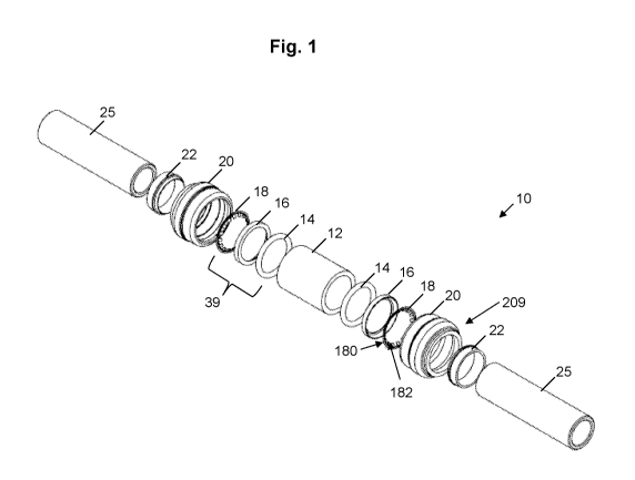
Fig. 1 is an exploded front perspective view of a device in accordance with
embodiments of the present invention.
Fig. 2 is a perspective view showing the elements of the device of Fig. 1 in
cross-
section.
Fig. 3 is a front cross-sectional view of one embodiment of the device of the
present
invention.
Fig. 4 is an enlarged view of the portion of the device taken from encircled
portion 4-
4 of Fig. 3.
Fig. 5 is a perspective view of a center body element in accordance with
embodiments
of the present invention.
Fig. 6 is a right side view of the center body element of Fig. 5.
Fig. 7 is a cross-sectional view of the center body element as taken along
line 7-7 of
Fig. 6.
3e
CA 03018105 2018-09-17
WO 2017/161072
PCT/US2017/022631
Fig. 8 is a rear right perspective view of a head connector in accordance with
embodiments of the present invention.
Fig. 9 is a front right perspective view of a head connector in accordance
with
embodiments of the present invention.
Fig. 10 is a right side view of the head connector of Fig. 9.
Fig. 11 is a cross-sectional view of the head connector as taken along line 11-
11 of
Fig. 10.
Fig. 12 is a right side view of a spacer gland in accordance with embodiments
of the
present invention.
Fig. 13 is a cross-sectional view of the spacer gland as taken along line 13-
13 of Fig.
12.
Fig. 14 is an enlarged view of the portion of the spacer gland taken from
encircled
portion 14-14 of Fig. 13.
Fig. 15 is an exploded front perspective view of a device with an installed
head
connector and packing arrangement on one side of the center body in accordance
with
embodiments of the present invention.
Fig. 16 is a perspective view showing the elements of the device of Fig. 15 in
cross-
section.
Modes for Carrying Out the Invention
In the device 10 of embodiments of the present invention as shown in Figs. 1
through
16, elements of the device as shown include: a fitting or conduit center body
member 12, at
least one sealing ring 14, at least one spacer gland 16, at least one grip
ring 18, at least one
head connector 20 and at least one release pusher or retainer ring 22. Figs. 1
through 3 also
show two tubes 25 connected using the device 10. In various embodiments, the
center body
member 12 and can be forged CW617N brass, with full porting and full flow
fitting, for
example. In other embodiments, the body member 12 can be a plastic material.
In various embodiments, the center body member 12 is a substantially
cylindrical
body having an exterior surface 120, and an interior surface 122 having a tube
stop 123
extending radially inwardly thereof The tube stop 123 includes first 126 and
second 128
radially extending edges, and an axially extending surface 125. The edges 126,
128 act to
stop the axial insertion of tubes during operation of the present invention,
and surface 125 is
generally axially aligned with the internal surfaces of inserted tubes to
facilitate smooth
movement of any materials or fluids inside of the tubes, including electrical
wiring, for
example. The interior surface 122 forms a cavity 30 extending axially through
the center
4
CA 03018105 2018-09-17
WO 2017/161072
PCT/US2017/022631
body member 12, as shown in Fig. 5. The center body member 12 also includes
axially outer
walls 124, as shown in Figs. 5 through 7, and the walls 124 can vary in
thickness depending
upon the particular application involved.
As shown in Figs. 1 through 4 and 8 through 11, one or more head connectors 20
can
.. be provided, each of which can include an interior packing arrangement 39
comprising at
least one sealing ring (which can be optionally lubricated) 14, a spacer gland
16 and a grip or
fastening ring 18. In various embodiments, the packing arrangement 39 also
includes a
retainer ring 22. Sealing member 14 can be substantially ring-shaped, and can
be formed of a
rubber-based material or similar rigid yet deformable material designed to
slightly compress
.. when pressure is applied.
Each head connector 20 is a substantially ring-shaped body with a tube
receiving
opening 200 therein, and each of the sealing ring 14, spacer gland 16, grip
ring 18 and
retainer ring 22 has a substantially ring-shaped body forming an opening
extending through
the body along an axis which is aligned with axis 222 of head connector when
installed.
.. Each of sealing ring 14, spacer gland 16, grip ring 18 and retainer ring 22
has an internal
diameter that allows for smooth and snug engagement of a piping or tubing
element external
surface 225. In various embodiments, the diameter of the fastening ring 18 to
the radially
interior edge of the fastening ring teeth 182 is less than the diameter of the
spacer gland 16,
sealing ring 14 and retainer ring 22, as the fastening ring teeth 182 engage
the outer surface
225 of an inserted tube 25 during operation. The diameter of the fastening
ring to the teeth
182 is manipulable during operation so as to permit insertion, removal and
retention of tube
elements 25 as described herein. The packing arrangements 39 are not housed
within the
center body member 12, but rather within each head connector 20.
As shown in Fig. 11, each head connector 20 is formed with an interior surface
65
having various axially extending wall surface segments 70, 72, 74, 76, 78 and
79, each of
which has a respective radial distance from the central axis 222 of the head
connector 20. For
instance, segment 70 has a radial distance R1, segment 72 has a radial
distance R2, segment
74 has a radial distance R3, segment 76 has a radial distance R4, segment 78
has a radial
distance R5, and segment 79 has a radial distance R6. It will be appreciated
that only
segments 76 and 79 have the same radial distance from central axis 222,
wherein radial
distance R4 is substantially equal to radial distance R6. These segments 76
and 79 assist in
forming a first radial housing compartment 33. As shown in Fig. 4, the outer
wall 120 of
center body connector 12 and the wall surface segment 78 also assist in
forming the first
radial housing compartment 33, which extends from axially inner edge 80 of
wall surface
5
CA 03018105 2018-09-17
WO 2017/161072
PCT/US2017/022631
segment 79 to axially outer edge 82 of wall surface segment 76. The interior
surface 65 of
the head connector 20 defines a cavity 200 extending axially through the head
connector 20
along axis 222.
As shown in Fig. 11, radial distance R5 is greater than the remaining radial
distances.
Radial distances R4 and R6 are greater than distances R1. R2 and R3. Radial
distance R3 is
greater than distances R2 and R1, and radial distance R2 is greater than
distance Rl. The
substantially equidistant nature of distances R4 and R6 assists in smooth and
snug
engagement of the outer wall 120 of center body connector 12 during operation.
Further, the
radial distance R3 to the second compartment 73 housing the sealing ring 14,
spacer gland 16
and fastening ring 18 is greater than the radial distance R2 to the
compartment 71 housing the
retainer ring 22, which is inapposite to the relationship of such compartments
in other push-
to-connect technologies employing a central fitting component. As the present
invention
employs a central body member 12 having no internal packing arrangement, and
further
employs a pair of head connectors 20 as shown in Figs. 1, 2 and 15-16, the
arrangement of
radial distances, including distances R2 and R3, assists in providing a
quickly assembled and
strong conduit device requiring no coining or split members, for example.
As can be seen in Figs. 4 and 8 through 11, wall surface segment 74 forms a
second
radial housing compartment 73 between axially outer edge 83 of segment 74 and
axially outer
edge 84 of segment 72. The axially outer wall 124 of center body member 12 and
outer
surface 225 of tube 25 also provide surface boundaries for the second radial
housing
compartment 73. Additionally, wall surface segment 72 forms a third radial
housing
compaitment 71 between axially outer edge 84 of segment 72 and axially outer
edge 86 of
segment 70. Third compartment 71 houses the radially outer ledge segment 91
and back wall
92 of the release pusher 22, as shown in Fig. 4.
As further shown in Figs. 4 and 8 through 11, head connector 20 is provided
with an
outer surface 209, an axially outer wall segment 216 and an axially inner wall
segment 201.
Segment 201 can be formed with a rounded edge 202 shared by first
circumferential segment
204, which extends radially outwardly along intermediate segment 206 to a
second
circumferential segment 208. Second circumferential segment 208 is provided
with a
rounded edge 210 shared by third circumferential segment 214. Circumferential
segments
204, 208 and 214 are substantially axially aligned with the center axis 222 of
the head
connector 20, wherein segment 208 has a diameter that is greater than the
respective
diameters of segments 204 and 214, and wherein segment 204 has a diameter that
is greater
than diameter 214.
6
CA 03018105 2018-09-17
As shown in Figs. 1 through 4 and 12 through 14, the spacer gland 16 has a
circumferential base 162, a sealing member-engaging surface 166 and fastening
ring-
engaging surfaces 160 and 163. In various embodiments, spacer gland 16 can
comprise an
injection-molded plastic or a metal material such as brass, for example.
Surface 160 engages
the base 180 of the fastening ring 18 and pinches the fastening ring base 180
against the
axially outer edge 84 of segment 72 of the head connector 20, whereas surface
163 is engages
the teeth 182 of the fastening ring 18 during operation. Further, fastening
ring teeth engaging
surface 163 can extend from surface 160 at an angle A of between approximately
6.5 degrees
and approximately 50 degrees from the circumferential base 162. In a
particular embodiment
of the present invention, angle A is approximately 37 degrees. In one
embodiment of the
present invention, the spacer gland 16 is split, including a first
circumferential end point and
a second circumferential end point that do not connect and thereby form a
slit, which allows
the gland to be manually pinched and compressed to facilitate installation
into the second
radial housing compartment 73.
As further shown in Figs. 1 and 4, the fastening ring 18 includes a
substantially
cylindrical base 180 that has a plurality of bifurcated or square edged teeth
182 extending
radially inwardly from and along the base 180 of the ring 18. The number of
teeth can
readily vary in number and size. The fastening ring 18 can comprise a spring
steel
formulation, for example, that enables the fastening ring to be malformed
during installation,
while springing back into its originally manufactured position once installed.
The fastening
ring can be split, in various embodiments of the present invention. Such split
arrangements
for the spacer gland and fastening ring are shown and described, for example,
in U.S. Patent
No. 9,068,860.
As shown in Figs. 1 through 4 and 15 through 16, the retainer ring 22 is
positioned on
the axially outward side 209 of the head connector, and is capable of axial
insertion into the
cavity 30 of the head connector 20 in order to lift the teeth 182 of the grip
ring 180 axially
inwardly and radially outwardly to permit insertion and removal of tubes 25 to
be connected
via the center body. In various embodiments, each head connector 20 is secured
to the center
body through applying glue in compartment 33 or by ultrasonic welding, for
example.
Among other things, it will be appreciated that the present invention assists
production efforts
by eliminating the time required for multiple molds associated with other push-
to-connect
technologies.
In various embodiments, the release pusher 22 is substantially cylindrical and
hollow
and includes an external tip 90 at the fastening ring engaging end thereof, as
shown in Fig. 4.
7
CA 03018105 2018-09-17
WO 2017/161072
PCT/US2017/022631
The release pusher 22 also includes a radially outer ledge segment 91, a ledge
back wall 92,
and a second outer wall segment 94. The pusher 22 can comprise an injection-
molded plastic
or a metal material such as brass, for example. When pressure is applied on
the back side 95
of the release pusher 22, the external tip 90 can engage the inside surface of
the fastening ring
.. teeth 182 and the ledge back wall 92 can removably engage the axially outer
edge 86 of
segment 70 of the head connector 20, as shown in FIG. 4. Once the release
pusher 22 is
inserted into the conduit formed by the head connector 20 and packing
arrangement 33, the
radially outer ledge segment 91 provides for flush engagement with the wall
segment 72 of
the head connector 20.
In various embodiments, the sealing ring 14, spacer gland 16 and fastening
ring 18
can be housed within the head connector 20 so as to substantially abut one
another within the
second radial housing element 73. Further, the fastening ring base 180 is
securely retained
between the surface 160 of spacer gland 16 and the axially outer edge 84 of
segment 72 of the
head connector 20. In this way, the fastening ring 18 does not move axially
within the center
.. body 12 during operation.
In operation, when two tubes 25 are to be joined, a pair of head connectors 20
is
provided, and a respective packing arrangement 33 is installed therein. For
example, a grip
ring 18 is inserted into the second radial housing compartment 73 of each head
connector 20,
followed by a spacer gland 16 and a sealing ring 14. A retaining ring 22 is
also inserted into
the third radial housing compartment 71 of each head connector 20. Next, the
center body
member 12 is provided and glue can optionally be inserted into the first
radial housing
compaitment 33 of the head connector. A head connector 20 with installed
packing
arrangement is then inserted on each end 111, 112 of the center body member
12, and secured
to the head connectors 20 via glue as it is dried, or by ultrasonic welding
processes if glue is
not employed. The securing of the head connectors 20 to the center body member
12 assists
in retaining the sealing member 14, spacer gland 16 and fastening ring 18
securely within
compaitment 73. A tube 25 with a release pusher tool positioned around the
circumference
of the tube 25 can then be inserted into the cavity 200 at one end of the head
connector 20,
and the tool (or alternatively, manual or similar pressure) can be applied to
the end 95 of the
retaining ring 22, thereby forcing the fastening ring teeth radially outwardly
such that the
tube 25 can be smoothly inserted until it reaches the tube stop 123 of the
center body member
12. At such time, the force on the retaining ring 22 can be released, thereby
allowing the
retaining ring back ledge 92 to rest within the third compartment 71, and
allowing the
8
CA 03018105 2018-09-17
WO 2017/161072
PCT/US2017/022631
fastening ring teeth 182 to engage the outer surface 225 of the tube 25. A
similar installation
of another tube 25 can take place at the other end of the head connector 20.
It will be appreciated that any and all dimensions described herein are
exemplary and
provided as embodiments associated with proper working operation of the
present invention.
Further, it will be appreciated that, in various embodiments of the present
invention, the
members of the push connect joint assembly can be formed through hydroforming
processes.
The invention may be embodied in other specific fomis without departing from
the
spirit or essential characteristics thereof The present embodiments are
therefore to be
considered in all respects as illustrative and not restrictive, the scope of
the invention being
indicated by the claims of the application rather than by the foregoing
description, and all
changes which come within the meaning and range of equivalency of the claims
are therefore
intended to be embraced therein.
9