Note: Descriptions are shown in the official language in which they were submitted.
-1-
DATA IN MOTION STORAGE SYSTEM AND METHOD
[0001] FIELD OF THE DISCLOSURE
[0002] The present disclosure relates to the field of information storage
technology and, in
particular, to a system in which information may be stored as electromagnetic
radiation in
motion, for example, as lasers or other optical beams carrying data and
transmitted or reflected
between structures or within structures, cavities and/or with/using different
transmission media,
including vacuum, crystals, nonlinear media, free space, optical waveguides or
optical fibers.
BACKGROUND OF THE DISCLOSURE
[0003] In an electromagnetic communication system, a maximum transmission
distance of the
signal, such as a beam of light, is dictated by the loss experienced by the
signal in free space or
in the optical fiber or other waveguide, the spreading of the signal carrying
the data due to
various dispersive and nonlinear effects, and the addition of noise from
sources including, but
not limited to, perturbations of the system, random scattering events and
spontaneous emission
of light. As a result, when transmitting a signal over longer distances, the
signal typically has to
be regenerated at various distance intervals. Full data signal regeneration is
typically considered
a "3R" process that includes data retiming, reshaping, and reamplification (or
amplification).
[0004] Laser-based data communication in space is well known. For example,
the Artemis
satellite of the European Space Agency has provided an optical data
transmission link with the
CNES Earth observation satellite, SPOT 4. Communication range in space for
optical
communication is reliable at several thousand kilometers. Laser or optical
communication over
distances orders of magnitude greater than this may also be achievable.
Date Recue/Date Received 2022-02-14
-2-
NASA's Optical Payload for Lasercomm Science (OPALS) project has also
successfully
demonstrated high data transfer rates using optical communication between
Earth stations and
the International Space Station. Another example, in January 2013, NASA
transmitted lasers
representing an image of the Mona Lisa to a lunar reconnaissance orbiter
roughly 390,000
kilometers away.
[0005] Conventional datacenters have a variety of drawbacks, including that
they may be
expensive to maintain, may require various types of media, and are subject to
being hacked into
and accessed physically or remotely without authorization, such that data may
can be copied,
destroyed, or otherwise changed without authorization access or attacked. In
addition, power
outages, natural disasters and calamities, such as fire, flooding,
earthquakes, and war, can impact
conventional terrestrial datacenters. Also data that has been erased from one
of these data centers
may be recoverable by a person with the right expertise. These data centers
also have the
disadvantage of substantial overhead costs such as rent, cooling expenses,
electricity costs, and
physical security. Conventionally, data storage units can be built out of
multiple racks, where
each (data) rack is comprised of multiple hard drives in (which can be based
on various
technologies) and computers, such as routers, switches, firewalls, and other
devices. This set up
has numerous limitations and challenges, including but not limited to, high
operating expenses,
as noted above, as well as requirements for rather large physical locations,
high consumption of
electric power, significant maintenance as well as high cooling needs.
[0006] Orienting and pointing of an electromagnetic beam in a laser context
can be done
using a gimbal, or an optical phase array, as well as other well-known
approaches used to point
to a fine angular accuracy. Each of the signal transmitter may be selectively
steered for optical
communication with the targets, such as reflecting surfaces. An inertial
reference system may be
used in concert with adjustable elevation settings to track the neighboring
satellites in the
constellation. Beam steering mirrors may be used to compensate for host
satellite jitter and slight
orbit differences. Further examples are provided in the discussion in the
National Academy of
Science Study "Laser Radar: Progress and Opportunities in Active Electro-
Optical Sensing"
2014 chaired by Dr. Paul McManamon, U.S. 5,602,838 to Kartalopoulos, U.S.
6,002,916 to
Lynch, U.S. 6,043,918 to Bozzay et al., U.S. 7,103,280 to Ionov et al., U.S.
8,913,894 to
Coleman et al., U.S. 2010/0269143 to Rabowsky, U.S. 2010/0279604 to Wood, U.S.
4,856,862
to Passmore et al.,
Date Recue/Date Received 2022-02-14
CA 03018142 2018-09-17
WO 2017/165429
PCT/US2017/023431
- 3 -
U.S. 4,815,804 to Desurview et al., U.S. 4,653,042 to d'Auria et al., U.S.
5,862,286 to
Imanishi et al., Pidishety, "Investigation of scalability of all-fiber fused
mode selective
coupler for generating multiple OAM states," in Proceedings of International
Conference on
Fiber Optics and Photonics, 2016, U.S 4,136,929 to Suzaki, McDonald et al.,
"Spatial
Solitary-Wave Optical Memory," Journal of the Optical Society of America B
(Optical
Physics), vol. 7, no. 7, pp. 1328-1335, 1990, Leo et al., "Temporal cavity
solitons in one-
dimensional Kerr media as bits in an all-optical buffer," Nature Photonics,
vol. 4, pp. 471-
476, 2010, U.S. 7,199,343 to Modley, U.S. 5,740,117 to Bona et al., Boyd et
al.,
"Applications of Slow Light in Telecommunications." Optics & Photonics News.
vol. 17, no.
4, pp. 18-23, 2006, G.B. 1998/000821 to Poustie et al., U.S. 4,479,701 to
Newton et al., U.S.
4,877,952 to Halemane et al., U.S. 4,469,397 to Shaw et al., U.S. 2007/0081785
to Hays,
U.S. 4,738,503 to Desurvire et al., U.S. 6,917,739 to Chen, U.S. 6,172,926 to
Drayer, U.S.
5,533,154 to Smith, U.S. 5,566,261 to Hall et al., U.S. 6,647,163 to Song,
U.S. 5,058,060 to
Su, U.S. 2003/0007230 to Kanko et al., U.S. 2002/0196488 to Myers, U.S.
4,166,212 to J.
Judenstein, U.S. 4,473,270 to Shaw, U.S. 8,582,972 to Small et al, U.S.
2009/0202191 to
Ramachandran, U.S. 7,177,510 to Ramachandran, U.S. 7,110,651 to Golwich et
al., U.S.
4,974,931 to Poole, and U.S. 7,103,239 to Kish, Jr. et al.
SUMMARY
[0007] A data storage system and method are described. In one embodiment, a
system
according to an aspect of the disclosure includes a data management system
configured to
manage digital data in the data storage system; a terrestrial transmitter
configured to transmit
a radio frequency signal carrying the digital data to a communication
satellite; the
communication satellite configured to convert the radio frequency signal to a
signal and to
transmit the signal to a first laser satellite; the first laser satellite
comprising a laser signal
generator configured to generate a laser signal carrying the digital data, and
the laser signal
generator configured to transmit the digital data to a second laser satellite;
the second laser
satellite configured to return to the first laser satellite the digital data
transmitted from the
first satellite; and the first laser satellite configured to return to the
second laser satellite the
digital data transmitted from the second laser satellite, such that the
digital data may be
transmitted in a recirculating loop of storage in motion, wherein at least one
of the first laser
satellite and the second laser satellite may be configured to retrieve a block
of data of the
digital data identified by the data management system. A recirculating loop,
according to an
CA 03018142 2018-09-17
WO 2017/165429
PCT/US2017/023431
- 4 -
aspect of the disclosure, may include a signal loop in which the signal is
maintained until the
system is shut off or disassembled or until the signal is erased.
[0008] In such a system, the data management system may identify the block
of data as
being responsive to a request for the block of data received, the block of
data being less than
an entirety of the digital data.
[0009] According to another aspect of the disclosure, disclosed is a data
storage system
that includes a recirculating loop configured to store data in motion and
comprising a first
vessel and a second vessel positioned remote from the first vessel; the first
vessel comprising
at least one selected from the group consisting of a signal generator and a
signal transmitter
configured to transmit the data to the second vessel; the second vessel
configured to return to
the first vessel the data transmitted from the first vessel; and the first
vessel configured to
return to the second vessel the data transmitted from the second vessel. A
signal may be
returned by reflecting all or part of it, or it may be returned by
regenerating the signal and
transmitting it.
[0010] A data management system of such a data storage system may be
configured to
manage the data in the data storage system, wherein at least one of the first
vessel and the
second vessel may be configured to retrieve a block of data of the data
identified by the data
management system as being responsive to a data retrieval request for the
block of data
received from outside the data storage system, the block of data being less
than an entirety of
the data.
[0011] In such a system, for each roundtrip of the signal through the
recirculating loop
the signal may be kept in motion.
[0012] In such a system, at least one of the first vessel and the second
vessel may be a
satellite.
[0013] In such a system, at least one of the first vessel and the second
vessel may be a
satellite in geosynchronous orbit around the earth. In such a system, at least
one of the first
vessel and the second vessel may be a ship, an aircraft, such as airplane, a
hot air balloon, or
a drone, a submarine, or a stationary sea structure, for example, an oil rig.
[0014] In such a system, the recirculating loop may compare a third vessel,
and the
second vessel may be configured to return the data to the first vessel via the
third vessel by
transmitting the data to the third vessel.
[0015] In such a system, the recirculating loop may be configured to
recirculate the data
between vessels recurring in consecutive sequence.
CA 03018142 2018-09-17
WO 2017/165429
PCT/US2017/023431
-5-
100161 In such a system, at least one of the first and the vessel may
comprise a reflecting
surface positioned and configured to return the signal.
[0017] In such a system, the second vessel may comprise a corner cube
positioned and
configured to return the signal. A land station signal link to such a
recirculating link may use
electromagnetic signaling, such as RF or optical signals, or other type
signaling.
[0018] In such a system, the at least one of the signal generator and the
signal transmitter
may generate an electromagnetic radiation signal carrying the data and
transmitted to the
second vessel.
[0019] In such a system, the at least one of the signal generator and the
signal transmitter
may generate an optical beam signal, for example, a laser signal, carrying the
data and
transmitted to the second vessel.
[0020] In such a system, the at least one of the signal generator and the
signal transmitter
may be configured to generate a multiplexed electromagnetic signal comprising
a first set of
multiplexed signals, each signal of the first set of multiplexed
electromagnetic signals
comprising a second set of multiplexed electromagnetic signals generated using
a
multiplexing scheme different from the first set of multiplexed signals.
[0021] In such a system, the first vessel comprises a system asset tracker
that may be
configured to maintain position information regarding the second vessel.
[0022] In such a system, the system may further comprise an error checker
configured to
perform cyclic redundancy check to ensure data integrity.
[0023] Such a system may also include a controller configured to receive,
at a first time, a
first request from outside the data storage system to perform a first
operation, the first
operation comprising one of a read operation, a write operation, and a delete
operation for a
first block of data of the data, and to receive, at a second time after the
first time, a second
request from outside the data storage system to perform a second operation,
the second
operation comprising one of the read operation, the write operation, and the
delete operation
for a second block of data of the data, wherein the system performs the first
operation after
performing the second operation.
[0024] In such a system, when the first operation is the read operation,
the second
operation may be the read operation; when the first operation is the write
operation, the
second operation may be the write operation, and when the first operation is
the delete
operation, the second operation may be the delete operation.
CA 03018142 2018-09-17
WO 2017/165429
PCT/US2017/023431
-6-
100251 In such a system, the at least one of the signal generator and the
signal transmitter
may be configured to generate a code division multiplexed signal as the
signal, the code
division multiplexed signal comprising a first set of multiplexed signals such
that a first
multiplexed signal of the first set carries data other than a second
multiplexed signal of the
first set.
[0026] In such a system, the at least one of the signal generator and the
signal transmitter
may be configured to generate an orbit angular momentum division multiplexed
signal as the
signal, the orbit angular momentum division multiplexed signal comprising a
first set of
multiplexed signals such that a first multiplexed signal of the first set
carries data other than a
second multiplexed signal of the first set.
[0027] In such a system, at least one of the signal generator and the
signal transmitter
may be configured to generate a space division multiplexed signal as the
signal, the space
division multiplexed signal comprising a first set of multiplexed signals such
that a first
multiplexed signal of the first set carries data other than a second
multiplexed signal of the
first set.
[0028] In such a system, the at least one of the signal generator and the
signal transmitter
may be configured to generate a polarization division multiplexed signal as
the signal, the
polarization division multiplexed signal comprising a first set of multiplexed
signals such that
a first multiplexed signal of the first set carries data other than a second
multiplexed signal of
the first set.
[0029] In such a system, the at least one of the signal generator and the
signal transmitter
may be configured to generate a frequency division multiplexed signal as the
signal, the
frequency division multiplexed signal comprising a first set of multiplexed
signals such that a
first multiplexed signal of the first set carries data other than a second
multiplexed signal of
the first set.
[0030] Such a system may also include a data management system configured
to
associate a data block carried by a portion of the signal with at least one of
a physical
property and a location of the portion of the signal; and a controller
configured to generate a
control signal controlling an operation on the data block, the control signal
may be generated
based on a clock signal with reference to the at least one of the physical
property and the
location of the portion of the signal.
[0031] Such a system may also include a data management system configured
to manage
data in the data storage system and configured to receive a request from
outside the data
CA 03018142 2018-09-17
WO 2017/165429
PCT/US2017/023431
- 7 -
storage system to at least one of delete, write and update a block of data in
the data, wherein
the recirculating loop comprises an eraser configured to erase, based on
information received
from the data management system, a first portion of the signal, the first
portion carrying the
data block, the data block being less than an entirely of the data.
[0032] According to another aspect of the disclosure, disclosed is a data
storage system
including a recirculating loop configured to maintain a laser signal carrying
the digital data in
motion and including an optical waveguide, an optical waveguide coupler, and a
regenerator;
a signal generator configured to generate a laser signal carrying the digital
data and to
transmit the laser signal into an input/output optical waveguide; the optical
waveguide
coupler coupling the laser signal between the input/output optical waveguide
and the optical
waveguide, and the regenerator coupled to the optical waveguide and configured
to amplify
and/or regenerate the laser signal through the optical waveguide.
[0033] Such a system may also include a data management system configured
to manage
digital data in the data storage system, wherein the recirculating loop may
comprise an eraser
configured to erase, according to timing based on information provided by the
data
management system, a portion of the laser signal carrying a block of data of
the digital data,
the portion of the laser signal being less than an entirety of the laser
signal.
[0034] In such a system, the signal generator may be configured to generate
a
multiplexed signal as the laser signal, the multiplexed signal comprising a
first set of
multiplexed laser signals, such that a first multiplexed laser signal of the
first set carries data
other than a second multiplexed laser signal of the first set, each laser
signal of the first set of
multiplexed signals comprising a second set of multiplexed laser signals
generated using a
multiplexing scheme different from the multiplexing scheme used to generate
the first set of
multiplexed signals.
[0035] In such a system, each laser signal of the second set of multiplexed
laser signals
may comprise a third set of multiplexed laser signals generated using a
multiplexing scheme
different from the multiplexing scheme used to generate the first set of
multiplexed signals
and from the multiplexing scheme used to generate the second set of
multiplexed signals.
[0036] According to a further aspect of the disclosure, a data storage
system disclosed
that includes a recirculating loop configured to maintain a signal carrying
data in motion and
including a waveguide and a waveguide coupler; the waveguide coupler
configured to couple
a signal carrying the data into the waveguide; and a signal conditioner
configured to
CA 03018142 2018-09-17
WO 2017/165429
PCT/US2017/023431
- 8 -
condition the signal conveyed through the waveguide by at least one of
amplifying and
regenerating the signal.
[0037] In such a system, the waveguide may comprise optical fiber.
[0038] Such a system may include a signal generator configured to transmit
the signal to
the waveguide coupler, wherein the signal generated by the signal generator
may be an
electromagnetic signal.
[0039] Such a system may include a signal generator configured to transmit
the signal to
the waveguide coupler, wherein the signal generated by the signal generator
may be a laser
signal.
[0040] In such a system, the recirculating loop may further comprise the
signal
conditioner, and the waveguide may comprise a first segment positioned to
convey the signal
between the waveguide coupler and the signal conditioner and a second segment
connected to
the signal conditioner, the first segment being free of direct physical
connection with the
second segment.
[0041] In such a system, the recirculating loop may comprise the signal
conditioner, and
the signal conditioner may comprise a signal amplifier configured to amplify
at least a
portion of the signal each time the signal passes through the signal
conditioner.
[0042] Such a system may include a data management system configured to
manage data
in the data storage system and configured to receive a request from outside
the data storage
system to at least one of delete, write and update a block of data in the
data, wherein the
recirculating loop may comprise an eraser configured to erase, based on
information received
from the data management system, a first portion of the signal, the first
portion carrying the
data block, the data block being less than an entirely of the data.
[0043] In such a system, the data management system may be configured to
generate
timing information according to the request, and the information received by
the eraser from
the data management system in the timing information.
[0044] Such a system may include a signal generator configured to transmit
the signal to
the waveguide coupler, wherein the signal carrying the data generated by the
signal generator
may be a signal multiplexed by a propagation-direction multiplexer configured
to transmit a
first portion of the signal through the recirculating loop in a first
direction and to transmit a
second portion of the signal through the recirculating loop in a second
direction different
from the first direction.
CA 03018142 2018-09-17
WO 2017/165429
PCT/US2017/023431
-9-
100451 Such a system may include a signal regenerator, wherein the signal
conditioner
may be a signal amplifier configured to amplify at least some of the signal,
wherein, the
signal regenerator may be configured to regenerate, at a first timing, only a
first portion of the
signal, the first portion of the signal being less than an entirety of the
signal, and to
regenerate, at a second timing after the first timing, only a second portion
of the signal, the
second portion of the signal being less than an entirety of the signal.
[0046] In such a system, the system may regenerate the signal
asynchronously such that
the second portion is a least recently regenerated portion of the signal.
[0047] In such a system, the system may regenerate only the first portion
of the signal at
a third timing, and may regenerate only the second portion of the signal at a
fourth timing, an
interval between the first and third timing being greater than an interval
between the second
and fourth timing.
[0048] In such a system, the system may regenerate only the first portion
of the signal
interleaved with the regenerating of only the second portion of the signal.
[0049] Such a system may also include a controller configured to receive,
at a first time, a
first request from outside the data storage system to perform a first
operation, the first
operation comprising one of a read operation, a write operation, and a delete
operation for a
first block of data of the data, and to receive, at a second time after the
first time, a second
request from outside the data storage system to perform a second operation,
the second
operation comprising one of the read operation, the write operation, and the
delete operation
for a second block of data of the data, wherein the system performs the first
operation after
performing the second operation.
[0050] In such a system, when the first operation is the read operation,
the second
operation may be the read operation; when the first operation is the write
operation, the
second operation may be the write operation, and when the first operation is
the delete
operation, the second operation may be the delete operation.
[0051] Such a system may also include a data integrity determiner
configured to
determine data integrity only of the first portion when the signal regenerator
regenerates the
first portion, and to determine data integrity only of the second portion when
the signal
regenerator regenerates the second portion.
[0052] In such a system, the system may further comprise an error cyclic
redundancy
checker configured to perform cyclic redundancy check to ensure data
integrity.
CA 03018142 2018-09-17
WO 2017/165429
PCT/US2017/023431
- 10 -
[0053] In such a system, the recirculating loop may further comprise a
signal filter
configured to impose signal loss on the signal in dependence, in a non-linear
manner, on
signal intensity of the signal.
[0054] In such a system, the recirculating loop may further comprise a
signal filter
configured to filter out a portion of the signal with signal intensity below a
first value.
[0055] In such a system, the recirculating loop further may comprise a
signal filter
configured to provide signal loss to a first portion of the signal, the first
portion of the signal
having a signal intensity greater than a second portion of the signal, wherein
the signal loss
provided may be mathematical function of a time varying intensity of the first
portion of the
signal.
[0056] In such a system, the recirculating loop may further comprise a
signal filter
configured to provide signal loss to a first portion of the signal and to a
second portion of the
signal, the first portion having a signal intensity greater than the second
portion, wherein the
signal loss provided to the first portion may be greater than a roundtrip
gain, and the signal
loss provided to the second portion may be less than the roundtrip gain.
[0057] In such a system, the recirculating loop further may comprise a
signal filter
comprising a material with a first index of refraction, the signal filter may
be configured to
provide a signal loss to a first portion of the signal with a signal intensity
below a first value,
and to change the index of refraction of the material so as to provide a
signal loss to a second
portion of the signal with a second intensity higher than the first value.
[0058] hi such a system, the waveguide coupler may comprise a first coupler
and a
second coupler, the first coupler configured to couple only a first portion of
the signal, and
the second coupler configured to couple only a second portion of the signal
other than the
first portion, wherein the first and second portions are multiplexed in the
signal as part of a
first multiplexing scheme.
[0059] In such a system, the first coupler may comprise a third coupler and
a fourth
coupler, the third coupler configured to couple only a third portion of the
signal other than the
second portion, and the fourth coupler configured to couple only a fourth
portion of the signal
other than the second portion and other than the third portion, wherein the
first portion may
comprise the third and fourth portions, and the third and fourth portions are
multiplexed in
the signal as part of a second multiplexing scheme different from the first
multiplexing
scheme.
CA 03018142 2018-09-17
WO 2017/165429
PCT/US2017/023431
-11-
100601 In such a system, the waveguide coupler may comprise a signal in-
coupler
configured to transmit the signal into the waveguide, and a signal out-coupler
configured to
remove signal from the waveguide, wherein the signal in-coupler may be
positioned at the
recirculating loop remote from the signal out-coupler.
[0061] In such a system, the waveguide may be a nanostructured optical
fiber.
[0062] Such a system may also include a signal generator configured to
transmit the
signal to the waveguide coupler, wherein the signal generator may be
configured to generate
a multiplexed electromagnetic signal as the signal, the multiplexed
electromagnetic signal
comprising a first set of multiplexed electromagnetic signals, such that a
first multiplexed
signal of the first set carries data other than a second multiplexed signal of
the first set,
wherein each signal of the first set of multiplexed electromagnetic signals
may comprise a
second set of multiplexed electromagnetic signals generated using a
multiplexing scheme
different from the multiplexing scheme used to generate the first set of
multiplexed
electromagnetic signals.
[0063] In such a system, each laser signal of the second set of multiplexed
electromagnetic signals may comprise a third set of multiplexed
electromagnetic signals
generated using a multiplexing scheme different from the multiplexing scheme
used to
generate the first set of multiplexed electromagnetic signals and from the
multiplexing
scheme used to generate the second set of multiplexed electromagnetic signals.
[0064] Such a system may also include a signal generator configured to
transmit the
signal to the waveguide coupler, wherein the signal generator may be
configured to generate
a code division multiplexed signal as the signal, the code division
multiplexed signal
comprising a first set of multiplexed signals such that a first multiplexed
signal of the first set
carries data other than a second multiplexed signal of the first set.
[0065] Such a system may also include a signal generator configured to
transmit the
signal to the waveguide coupler, wherein the signal generator may be
configured to generate
an orbit angular momentum division multiplexed signal as the signal, the orbit
angular
momentum division multiplexed signal comprising a first set of multiplexed
signals such that
a first multiplexed signal of the first set carries data other than a second
multiplexed signal of
the first set.
[0066] Such a system may also include a signal generator configured to
transmit the
signal to the waveguide coupler, wherein the signal generator may be
configured to generate
a space division multiplexed signal as the signal, the space division
multiplexed signal
CA 03018142 2018-09-17
WO 2017/165429
PCT/US2017/023431
- 12 -
comprising a first set of multiplexed signals such that a first multiplexed
signal of the first set
carries data other than a second multiplexed signal of the first set.
[0067] Such a system may also include a signal generator configured to
transmit the
signal to the waveguide coupler, wherein the signal generator may be
configured to generate
a polarization division multiplexed signal as the signal, the polarization
division multiplexed
signal comprising a first set of multiplexed signals such that a first
multiplexed signal of the
first set carries data other than a second multiplexed signal of the first
set.
[0068] Such a system may also include a signal generator configured to
transmit the
signal to the waveguide coupler, wherein the signal generator may be
configured to generate
a frequency division multiplexed signal as the signal, the frequency division
multiplexed
signal comprising a first set of multiplexed signals such that a first
multiplexed signal of the
first set carries data other than a second multiplexed signal of the first
set.
[0069] Such a system may also include a data management system configured
to
associate a data block carried by a portion of the signal with at least one of
a physical
property and a location of the portion of the signal; and a controller
configured to generate a
control signal controlling an operation on the data block, the control signal
generated based
on a clock signal with reference to the at least one of the physical property
and the location of
the portion of the signal.
[0070] Such a system may also include a data management system configured
to manage
data in the data storage system and configured to receive a request from
outside the data
storage system to at least one of delete, write and update a block of data in
the data, wherein
the recirculating loop may comprise an eraser configured to erase, based on
information
received from the data management system, a first portion of the signal, the
first portion
carrying the data block, the data block being less than an entirely of the
data.
[0071] In such a system, the signal conditioner may be configured to
provide a first signal
gain to a first portion of the signal, wherein the first signal gain may be
provided according to
information regarding signal intensity obtained for a previous roundtrip of
the signal through
the recirculating loop.
[0072] In such a system, the signal conditioner may be configured to
provide filtering of
the signal by providing signal amplification to a first portion of the signal,
wherein the signal
amplification may be provided to the first portion when the first portion
meets a phase-
matching condition.
CA 03018142 2018-09-17
WO 2017/165429
PCT/US2017/023431
- 13 -
[0073] In such a system, the signal conditioner may be configured to
provide a pump
beam and an idler beam, the pump beam and the idler beam configured to provide
the
filtering.
[0074] Such a system may also include an optical cavity comprising a
recirculating loop
configured to maintain an optical signal carrying data in motion, and the
recirculating loop
including a signal coupler, a first signal returner, and a signal conditioner
configured to
condition the signal by at least one of amplifying and regenerating the
signal; the signal
coupler configured to couple at least a portion of the signal into the optical
cavity by
transmitting the signal to the first signal returner; the first signal retumer
positioned and
configured to return the signal to the signal coupler; and the signal coupler
configured to
return the signal received from the first signal returner to the first signal
returner.
[0075] In such a system, the signal coupler may comprise a signal in-
coupler configured
to transmit the signal into the optical cavity, and a signal out-coupler
configured to remove
signal from the optical cavity, wherein the signal in-coupler may be
positioned at the optical
cavity remote from the signal out-coupler.
[0076] In such a system, the loop comprises a second signal returner, and
the first signal
returner may be configured to return the signal to the signal coupler by
transmitting the signal
to the second signal returner.
[0077] In such a system, the optical cavity may comprise a continuous
reflecting surface
comprising the first signal returner and the second signal returner.
[0078] In such a system, the first signal returner may return the signal by
reflecting the
signal off a reflecting surface.
[0079] According to an aspect of the disclosure, also provided is a method
of filtering an
optical signal, the method including amplifying the optical signal by
providing signal gain;
and imposing signal loss on the optical signal in dependence, in a non-linear
manner, on
signal intensity of the optical signal, wherein the imposing the signal loss
includes providing
signal loss to a first portion of the optical signal, the first portion of the
optical signal having
a signal intensity greater than a second portion of the optical signal, the
signal loss provided
to the first portion being greater than the signal gain; and providing to the
second portion
signal loss less than the signal gain.
[0080] In such a method, the signal loss provided may be a mathematical
function of a
time varying intensity of the first portion of the signal.
CA 03018142 2018-09-17
WO 2017/165429
PCT/US2017/023431
- 14 -
[0081] In such a method, the signal filter may comprise a material with a
first index of
refraction, the signal filter configured to provide the signal loss to a third
portion of the signal
with a signal intensity below a first value, and the method may comprise
changing the index
of refraction of the material so as to provide the signal loss to the first
portion of the signal
with a second intensity higher than the first value.
[0082] Also described is a data storage method using a recirculating loop
configured to
maintain a signal carrying data in motion and including a signal introducer
and a signal
returner. This method may include introducing, by the signal introducer, the
signal carrying
the data into the recirculating loop: returning, by the signal returner, the
signal to the signal
introducer; and returning, by the signal introducer, the signal received from
the signal
returner to the signal returner.
[0083] In such a method, the signal returner may be a waveguide, and the
signal
introducer may be a waveguide coupler configured to couple the signal between
a signal
generator and the waveguide.
[0084] In such a method, the signal returner may comprise a reflecting
surface.
[0085] In such a method, the signal introducer may be positioned on a
vessel.
[0086] Such a method may also include recirculating a first portion of the
signal through
the recirculating loop in a first direction; and recirculating a second
portion of the signal
through the recirculating loop in a second direction different from the first
direction, the first
portion being other than the first portion.
[0087] In such a method, a signal generator may be configured to generate a
multiplexed
electromagnetic signal as the signal, the multiplexed electromagnetic signal
comprising a first
set of multiplexed electromagnetic signals, such that a first multiplexed
signal of the first set
carries data other than a second multiplexed signal of the first set, wherein
each signal of the
first set of multiplexed electromagnetic signals may comprise a second set of
multiplexed
electromagnetic signals generated using a multiplexing scheme different from
the
multiplexing scheme used to generate the first set of multiplexed
electromagnetic signals.
[0088] In such a method, each signal of the second set of multiplexed
electromagnetic
signals may comprise a third set of multiplexed electromagnetic signals
generated using a
multiplexing scheme different from the multiplexing scheme used to generate
the first set of
multiplexed electromagnetic signals and from the multiplexing scheme used to
generate the
second set of multiplexed electromagnetic signals.
CA 03018142 2018-09-17
WO 2017/165429
PCT/US2017/023431
- 15 -
[0089] In such a method, a signal generator may be configured to generate a
code
division multiplexed signal as the signal, the code division multiplexed
signal comprising a
first set of multiplexed signals such that a first multiplexed signal of the
first set carries data
other than a second multiplexed signal of the first set.
[0090] In such a method, a signal generator may be configured to generate
an orbit
angular momentum division multiplexed signal as the signal, the orbit angular
momentum
division multiplexed signal comprising a first set of multiplexed signals such
that a first
multiplexed signal of the first set carries data other than a second
multiplexed signal of the
first set.
[0091] In such a method, a signal generator may be configured to generate a
space
division multiplexed signal as the signal, the space division multiplexed
signal comprising a
first set of multiplexed signals such that a first multiplexed signal of the
first set carries data
other than a second multiplexed signal of the first set.
[0092] In such a method, a signal generator may be configured to generate a
polarization
division multiplexed signal as the signal, the polarization division
multiplexed signal
comprising a first set of multiplexed signals such that a first multiplexed
signal of the first set
carries data other than a second multiplexed signal of the first set.
[0093] In such a method, a signal generator may be configured to generate a
frequency
division multiplexed signal as the signal, the frequency division multiplexed
signal
comprising a first set of multiplexed signals such that a first multiplexed
signal of the first set
carries data other than a second multiplexed signal of the first set.
[0094] In such a method, a data management system may be configured to
associate a
data block carried by a portion of the signal with at least one of a physical
property and a
location of the portion of the signal; and the method may further include
generating a control
signal controlling an operation on the data block, the control signal
generated based on a
clock signal with reference to the at least one of the physical property and
the location of the
portion of the signal.
[0095] In such a method, a data management system may be configured to
manage data
in the data storage system; and the method may further include receiving a
request from
outside the data storage system to at least one of delete, write and update a
block of data in
the data; and erasing, by an eraser comprised in the recirculating loop, based
on information
received from the data management system, a first portion of the signal, the
first portion
carrying the data block, the data block being less than an entirely of the
data.
-16-
[0096] Such a method may also include providing, by a signal conditioner
positioned in the
recirculating loop, a first signal gain to a first portion of the signal,
wherein the first signal gain
may be provided according to information regarding signal intensity obtained
for a previous
roundtrip of the signal through the recirculating loop.
[0097] Such a method may also include providing, by a signal conditioner,
filtering of the
signal by providing signal amplification to a first portion of the signal,
when the first portion
meets a phase-matching condition.
[0097a] According to one aspect of the invention, there is provided a data
storage system
comprising:
a data management system configured to manage digital data in the data storage
system;
a terrestrial transmitter configured to transmit a radio frequency signal
carrying the digital
data to a communication satellite;
the communication satellite configured to transmit the data to a first laser
satellite;
the first laser satellite comprising a laser signal generator configured to
generate a laser
signal carrying the digital data, and the laser signal generator configured to
transmit the digital
data to a second laser satellite;
the second laser satellite configured to return to the first laser satellite
the digital data
transmitted from the first satellite; and
the first laser satellite configured to return to the second laser satellite
the digital data
transmitted from the second laser satellite, such that the digital data is
transmitted in a
recirculating loop of storage in motion,
wherein at least one of the first laser satellite and the second laser
satellite is configured
to retrieve a block of data of the digital data identified by the data
management system.
10097b1 According to one aspect of the invention, there is provided a data
storage system
comprising:
a recirculating loop configured to store data in motion and comprising a first
vessel and a
second vessel positioned remote from the first vessel;
the first vessel comprising at least one selected from the group consisting of
a signal
generator and a signal transmitter configured to transmit the data to the
second vessel;
the second vessel configured to return to the first vessel the data
transmitted from the first
vessel; and
Date Recue/Date Received 2022-02-14
-16a-
the first vessel configured to return to the second vessel the data
transmitted from the
second vessel.
[0097c] According to one aspect of the invention, there is provided a data
storage system
comprising:
a recirculating loop configured to store data in motion and comprising a first
vessel and a
second vessel positioned remote from the first vessel;
the first vessel comprising at least one selected from the group consisting of
a signal
generator and a signal transmitter configured to transmit the data to the
second vessel;
the second vessel configured to return to the first vessel the data
transmitted from the first
vessel;
the first vessel configured to return to the second vessel the data
transmitted from the
second vessel; and
a data management system configured to manage the data in the data storage
system,
wherein at least one of the first vessel and the second vessel is configured
to retrieve a block of
data of the data identified by the data management system as being responsive
to a data retrieval
request for the block of data received from outside the data storage system,
the block of data
being less than an entirety of the data.
[0097d] According to one aspect of the invention, there is provided a data
storage system
comprising:
a recirculating loop configured to store data in motion and comprising a first
vessel and a
second vessel positioned remote from the first vessel;
the first vessel comprising at least one selected from the group consisting of
a signal
generator and a signal transmitter configured to transmit the data to the
second vessel;
the second vessel configured to return to the first vessel the data
transmitted from the first
vessel;
the first vessel configured to return to the second vessel the data
transmitted from the
second vessel; and
wherein the at least one selected from the group consisting of the signal
generator and the
signal transmitter is configured to transmit to the second vessel a signal
carrying the data as a
signal multiplexed by a propagation-direction multiplexer, and the
transmitting comprises
transmitting a first portion of the signal through the recirculating loop as a
first beam and
Date Recue/Date Received 2022-02-14
-16b-
transmitting a second portion of the signal through the recirculating loop as
a second beam with a
propagation path physically separated from the first beam.
[0097e] According to one aspect of the invention, there is provided a data
storage system
comprising:
a recirculating loop configured to store data in motion and comprising a first
vessel and a
second vessel positioned remote from the first vessel;
the first vessel comprising at least one selected from the group consisting of
a signal
generator and a signal transmitter configured to transmit the data to the
second vessel;
the second vessel configured to return to the first vessel the data
transmitted from the first
vessel;
the first vessel configured to return to the second vessel the data
transmitted from the
second vessel; and
wherein at least one of the signal generator and the signal transmitter is
configured to
generate a multiplexed electromagnetic signal carrying the data and comprising
a first set of
multiplexed signals, each signal of the first set of multiplexed
electromagnetic signals
comprising a second set of multiplexed electromagnetic signals generated using
a multiplexing
scheme different from the first set of multiplexed signals.
1009711 According to one aspect of the invention, there is provided a data
storage system
comprising:
a recirculating loop configured to store data in motion and comprising a first
vessel and a
second vessel positioned remote from the first vessel;
the first vessel comprising at least one selected from the group consisting of
a signal
generator and a signal transmitter configured to transmit the data to the
second vessel;
the second vessel configured to return to the first vessel the data
transmitted from the first
vessel;
the first vessel configured to return to the second vessel the data
transmitted from the
second vessel; and
a controller configured to receive, at a first time, a first request from
outside the data
storage system to perform a first operation, the first operation comprising
one of a read
operation, a write operation, and a delete operation for a first block of data
of the data, and to
receive, at a second time after the first time, a second request from outside
the data storage
Date Recue/Date Received 2022-02-14
-16c-
system to perform a second operation, the second operation comprising one of
the read
operation, the write operation, and the delete operation for a second block of
data of the data,
wherein the system performs the first operation after performing the second
operation.
[0097g] According to one aspect of the invention, there is provided a data
storage system
comprising:
a recirculating loop configured to store data in motion and comprising a first
vessel and a
second vessel positioned remote from the first vessel;
the first vessel comprising at least one selected from the group consisting of
a signal
generator and a signal transmitter configured to transmit the data to the
second vessel;
the second vessel configured to return to the first vessel the data
transmitted from the first
vessel;
the first vessel configured to return to the second vessel the data
transmitted from the
second vessel; and
wherein the at least one of the signal generator and the signal transmitter is
configured to
generate a code division multiplexed signal carrying the data, the code
division multiplexed
signal comprising a first set of multiplexed signals such that a first
multiplexed signal of the first
set carries data other than a second multiplexed signal of the first set.
[0097h] According to one aspect of the invention, there is provided a data
storage system
comprising:
a recirculating loop configured to store data in motion and comprising a first
vessel and a
second vessel positioned remote from the first vessel;
the first vessel comprising at least one selected from the group consisting of
a signal
generator and a signal transmitter configured to transmit the data to the
second vessel;
the second vessel configured to return to the first vessel the data
transmitted from the first
vessel;
the first vessel configured to return to the second vessel the data
transmitted from the
second vessel; and
wherein the at least one of the signal generator and the signal transmitter is
configured to
generate an orbital angular momentum division multiplexed signal carrying the
data, the orbital
angular momentum division multiplexed signal comprising a first set of
multiplexed signals such
Date Recue/Date Received 2022-02-14
-16d-
that a first multiplexed signal of the first set carries data other than a
second multiplexed signal
of the first set.
[0097i] According to one aspect of the invention, there is provided a data
storage system
comprising:
a recirculating loop configured to store data in motion and comprising a first
vessel and a
second vessel positioned remote from the first vessel;
the first vessel comprising at least one selected from the group consisting of
a signal
generator and a signal transmitter configured to transmit the data to the
second vessel;
the second vessel configured to return to the first vessel the data
transmitted from the first
vessel;
the first vessel configured to return to the second vessel the data
transmitted from the
second vessel; and
wherein the at least one of the signal generator and the signal transmitter is
configured to
generate a space division multiplexed signal carrying the data, the space
division multiplexed
signal comprising a first set of multiplexed signals such that a first
multiplexed signal of the first
set carries data other than a second multiplexed signal of the first set.
1009711 According to one aspect of the invention, there is provided a data
storage system
comprising:
a recirculating loop configured to store data in motion and comprising a first
vessel and a
second vessel positioned remote from the first vessel;
the first vessel comprising at least one selected from the group consisting of
a signal
generator and a signal transmitter configured to transmit the data to the
second vessel;
the second vessel configured to return to the first vessel the data
transmitted from the first
vessel;
the first vessel configured to return to the second vessel the data
transmitted from the second
vessel; and
wherein the at least one of the signal generator and the signal transmitter is
configured to
generate a polarization division multiplexed signal carrying the data, the
polarization division
multiplexed signal comprising a first set of multiplexed signals such that a
first multiplexed
signal of the first set carries data other than a second multiplexed signal of
the first set.
Date Recue/Date Received 2022-02-14
-16e-
10097k] According to one aspect of the invention, there is provided a data
storage system
comprising:
a recirculating loop configured to store data in motion and comprising a first
vessel and a
second vessel positioned remote from the first vessel;
the first vessel comprising at least one selected from the group consisting of
a signal
generator and a signal transmitter configured to transmit the data to the
second vessel;
the second vessel configured to return to the first vessel the data
transmitted from the first
vessel;
the first vessel configured to return to the second vessel the data
transmitted from the
second vessel; and
wherein the at least one of the signal generator and the signal transmitter is
configured to
generate a wavelength division multiplexed signal carrying the data, the
wavelength division
multiplexed signal comprising a first set of multiplexed signals such that a
first multiplexed
signal of the first set carries data other than a second multiplexed signal of
the first set.
1009711 According to one aspect of the invention, there is provided a data
storage system
comprising:
a recirculating loop configured to store data in motion and comprising a first
vessel and a
second vessel positioned remote from the first vessel;
the first vessel comprising at least one selected from the group consisting of
a signal
generator and a signal transmitter configured to transmit the data to the
second vessel;
the second vessel configured to return to the first vessel the data
transmitted from the first
vessel;
the first vessel configured to return to the second vessel the data
transmitted from the
second vessel;
a data management system configured to associate a data block carried by a
portion of
signal with at least one of a physical property and a location of the portion
of the signal; and
a controller configured to generate a control signal controlling an operation
on the data
block, the control signal generated based on a clock signal with reference to
the at least one of
the physical property and the location of the portion of the signal.
Date Recue/Date Received 2022-02-14
-16f-
10097m] According to one aspect of the invention, there is provided a data
storage system
comprising:
a recirculating loop configured to store data in motion and comprising a first
vessel and a
second vessel positioned remote from the first vessel;
the first vessel comprising at least one selected from the group consisting of
a signal
generator and a signal transmitter configured to transmit the data to the
second vessel;
the second vessel configured to return to the first vessel the data
transmitted from the first
vessel;
the first vessel configured to return to the second vessel the data
transmitted from the
second vessel; and
a data management system configured to manage data in the data storage system
and
configured to receive a request from outside the data storage system to at
least one of delete,
write and update a block of data in the data, wherein the recirculating loop
comprises an eraser
configured to erase, based on information received from the data management
system, a first
portion of the signal carrying the data, the first portion carrying the data
block, the data block
being less than an entirety of the data.
[0097n] According to one aspect of the invention, there is provided a data
storage method
comprising:
transmitting, by at least one selected from the group consisting of a signal
generator and a
signal transmitter positioned at a first vessel, data carried by a signal to a
second vessel, wherein
the second vessel is positioned remote from the first vessel, and a
recirculating loop configured
to store the data in motion comprises the first vessel and the second vessel;
returning, by the second vessel, to the first vessel the data transmitted from
the first
vessel;
returning, by the first vessel, to the second vessel the data transmitted from
the second
vessel;
managing the data in the data storage system by a data management system; and
retrieving, by at least one of the first vessel and the second vessel, a block
of data of the
data identified by the data management system as being responsive to a data
retrieval request for
the block of data received from outside the data storage system, the block of
data being less than
an entirety of the data.
Date Recue/Date Received 2022-02-14
-16g-
1009701 According to one aspect of the invention, there is provided a data
storage system
comprising:
a plurality of communications nodes operable to recirculate signals carrying
data through
a recirculating loop comprising the signal communications nodes, and
a data management system configured to manage the data in the data storage
system;
wherein: at least one of the communications nodes comprises a signal receiver
operable to
receive the signals from another one of the communication nodes through a free
space medium,
at least one of the communications nodes comprises a signal transmitter
operable to transmit the
signals to another one of the communication nodes through the free space
medium, and at least
one of the communications nodes is configured to retrieve a block of data of
the data identified
by the data management system as being responsive to a data retrieval request
for the block of
data received from outside the data storage system, the block of data being
less than an entirety
of the data.
[0097p] According to one aspect of the invention, there is provided a data
storage system
comprising:
a recirculating loop configured to maintain a laser signal carrying digital
data in motion
and including an optical waveguide, an optical waveguide coupler, and a
regenerator;
a signal generator configured to generate the laser signal carrying the
digital data and to
transmit the laser signal into an input/output optical waveguide;
the optical waveguide coupler coupling the laser signal between the
input/output optical
waveguide and the optical waveguide; and
the regenerator coupled to the optical waveguide and configured to at least
one of amplify and
regenerate the laser signal through the optical waveguide.
[0097q] According to one aspect of the invention, there is provided a data
storage system
comprising:
a recirculating loop configured to maintain a signal carrying data in motion
and including
a waveguide and a waveguide coupler;
the waveguide coupler configured to couple the signal carrying the data into
the
waveguide; and
a signal conditioner configured to condition the signal conveyed through the
waveguide by at least one of amplifying and regenerating the signal.
Date Recue/Date Received 2022-02-14
-16h-
10097r1 According to one aspect of the invention, there is provided a data
storage in motion
system comprising:
a recirculating loop comprising an optical cavity configured to maintain an
optical signal
carrying data in motion, and the recirculating loop including a signal
coupler, a first signal
returner, and a signal conditioner configured to condition the signal by
amplifying the signal;
the signal coupler configured to couple at least a portion of the signal into
the optical
cavity by transmitting the signal to the first signal returner;
the first signal returner positioned and configured to return the signal to
the signal
coupler;
the signal coupler configured to return the signal received from the first
signal returner to
the first signal returner; and
a signal regenerator configured to regenerate, at a first timing, only a first
portion of
the signal, the first portion of the signal being less than an entirety of the
signal, and to
regenerate, at a second timing after the first timing, only a second portion
of the signal, the
second portion of the signal being less than an entirety of the signal.
[0097s] According to one aspect of the invention, there is provided a data
storage method
using a recirculating loop configured to maintain a signal carrying data in
motion and including a
signal introducer and a signal returner, the method comprising:
introducing, by the signal introducer, the signal carrying the data into the
recirculating
loop;
returning, by the signal returner, the signal to the signal introducer; and
returning, by the signal introducer, the signal received from the signal
returner to the
signal returner.
10097t] According to one aspect of the invention, there is provided a data
storage system
comprising:
a recirculating loop operable to store signals carrying data in motion, the
recirculating
loop including a waveguide and including a waveguide coupler operable to
couple the signals
carrying the data into the waveguide; and
a signal conditioner operable to amplify or regenerate the signals, wherein
the
waveguide coupler is operable to couple a first subset of the signals into the
waveguide such that
the first subset of signals travels in the recirculating loop in a first
direction, and to couple a
Date Recue/Date Received 2022-02-14
-16i-
second subset of the signals into the waveguide such that the second subset of
signals travels in
the recirculating loop in a second direction opposite the first direction.
[0097u] According to one aspect of the invention, there is provided a data
storage system
comprising:
a recirculating loop operable to store signals carrying data in motion, the
recirculating
loop including a waveguide and a waveguide coupler operable to couple the
signals carrying the
data into the waveguide; and
a signal conditioner operable to amplify or regenerate the signals, and a
signal
generator operable to provide the signals to the recirculating loop such that
the signals
concurrently traverse the recirculating loop repeatedly, wherein the waveguide
coupler is
configured to place a first subset of the signals into the recirculating loop
using a first type of
multiplexing, and wherein the waveguide coupler is configured to place a
second different subset
of the signals into the recirculating loop using a second type of multiplexing
different from the
first type of multiplexing.
10097v] According to one aspect of the invention, there is provided a data
storage system
comprising:
a recirculating loop operable to store signals carrying data in motion, the
recirculating
loop including a waveguide, a waveguide coupler operable to couple the signals
carrying the data
into the waveguide, and a signal amplifier operable to amplify a particular
one of the signals
after each cycle of the particular signal traversing the recirculating loop;
and
a signal regenerator operable to regenerate the particular signal at a
frequency
different from a frequency at which the particular signal is amplified within
the recirculating
loop.
[0097w] According to one aspect of the invention, there is provided a data
storage system
comprising:
a recirculating loop operable to store signals carrying data in motion, the
recirculating
loop including a multi-mode fiber and an optical coupler operable to couple
the signals carrying
the data into the multi-mode fiber, wherein the optical coupler is operable to
couple some of the
signals into a first mode of the multi-mode fiber and to couple other ones of
the signals into a
second, different mode of the multi-mode fiber.
Date Recue/Date Received 2022-02-14
-16j-
[0097x] According to one aspect of the invention, there is provided a data
storage system
comprising:
a recirculating loop operable to store signals carrying data in motion, the
recirculating
loop including a waveguide, a waveguide coupler operable to couple the signals
into the
waveguide such that the signals recirculate in the recirculating loop, and a
signal amplifier
operable to amplify a particular one of the signals after each cycle of the
particular signal
traversing the recirculating loop;
a signal regenerator operable to regenerate the particular signal at a first
scheduled time; a
data acquisition module operable to read the particular signal from the
recirculating loop at a
second scheduled time; and
a control module operable to control operation of the signal regenerator and
the data
acquisition module according to scheduling data specifying the first and
second scheduled times,
wherein the control module is operable to determine each of the first and
second scheduled times
independently of one another.
[0098] Other features and advantages of the present invention will become
apparent from the
following description of the invention, which refers to the accompanying
drawings.
BRIEF DESCRIPTION OF THE DRAWINGS
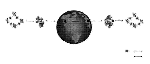
[0099] Fig. 1 illustrates major constituents of a satellite-based
information storage system,
according to an example of the present disclosure.
[00100] Fig. 2A illustrates components of an Earth station that communicates
with the user
and with the satellite-based information storage system, according to an
example of the present
disclosure.
[00101] Fig. 2B illustrates a system whereby the user communicates firstly
with a satellite,
where the Earth Station may or may not be used to hold all or part of the DMS
and other
components, according to an example of the present disclosure.
[00102] Figs. 3-8 illustrate additional examples of positioning the
satellites, according to an
aspect of the present disclosure.
[00103] Fig. 9 is an illustration of an example of corner cube for receiving
and returning a
signal.
Date Recue/Date Received 2022-02-14
-16k-
1001041 Figs. 10 and 11 illustrate examples of an electromagnetic signal
satellite transmitting
an electromagnetic signal to a reflection structure, illustrated in Fig. 10 as
a corner cube, and the
satellite receiving the reflected signal back, according to an aspect of the
present disclosure.
[00105] Fig. 12 illustrates an example of communication system between a first
electromagnetic signal communication device transmitting an electromagnetic
signal through a
waveguide to a second electromagnetic communication device, and the second
electromagnetic
communication device transmitting the signal back to the first electromagnetic
communication
device, according to an aspect of the present disclosure.
Date Recue/Date Received 2022-02-14
CA 03018142 2018-09-17
WO 2017/165429
PCT/US2017/023431
- 17 -
[00106] Fig. 13 is an illustration of an example of a terrestrial or
subterranean
configuration in which a first electromagnetic communication signal device
transmits the
electromagnetic communication signal to a reflector surface, which may be a
corner cube or
another type of reflector, which is then reflected back to the electromagnetic
signal
communication device, according to an aspect of the present disclosure.
[00107] Fig. 14 is an illustration of an example of an air-based
implementation of an
aspect of the invention, in which aircraft or other airborne vessels or
vehicles or structures
have electromagnetic signal communication devices which reflect, or regenerate
and
retransmit, the electromagnetic signal to one another, according to an aspect
of the present
disclosure.
[00108] Fig. 15 is an illustration of an example of an air-based
implementation in which
one or more structure or an aircraft or airborne vehicle or vessel includes a
first
electromagnetic signal communication device which transmits the
electromagnetic signal to a
second electromagnetic communication device mounted on or to a second
aircraft, illustrated
for illustrative purposes as an airplane, which may be then reflected back to
the first
electromagnetic signal communication device, or has a structure such as a
corner cube or
other type of reflective surface that reflects it back the electromagnetic
signal to the first
electromagnetic signal communication device, according to an aspect of the
present
disclosure.
[00109] Fig. 16 is an illustration of an example of another air-based
implementation
similar to the embodiment of Fig. 14, but the electromagnetic signal
communication devices
and/or reflective structures are mounted on airborne vessels without jet
engines or propellers,
shown, by way of example, as hot air balloons, helium balloons or blimps,
according to an
aspect of the present disclosure.
[00110] Fig. 17 is an illustration of an example of a sea-based implementation
of aspects
of the invention in which a first electromagnetic signal communication device
is mounted on
a sea-based vessel or vehicle, shown by way of illustrative example as a
submarine,
transmitting the electromagnetic signal to a second electromagnetic signal
communication
device, which may be attached to or housed in a vessel, shown by way of
illustrative example
as a ships and submarines, which then may reflect back the electromagnetic
signal to the first
electromagnetic signal communication device or may regenerate the signal and
re-transmit
the electromagnetic signal to the first electromagnetic communication device,
according to an
aspect of the present disclosure.
CA 03018142 2018-09-17
WO 2017/165429
PCT/US2017/023431
- 18 -
[00111] Fig. 18 is an illustration of an overview of a system for
communicating between
signal receivers A and B using laser communication, with the receivers forming
a signal loop
with a reflector, according to an aspect of the disclosure.
[00112] Fig. 19 is an illustration of an overview of a system for
communicating between
signal receivers A and B using laser communication, with the receivers forming
a signal loop,
according to an aspect of the disclosure.
[00113] Fig. 20 is a schematic illustration of an example of a signal moving
through a
loop, such as through a waveguide.
[00114] Fig. 21 is a schematic illustration of an example of an electronic
control system to
enable management of the data recirculating in a loop-based storage in motion
system using a
waveguide, according to an aspect of the present disclosure.
[00115] Fig. 22 is a schematic illustration of an example of a loop for
data storage in
motion using a fiber optic spool, according to an aspect of the present
disclosure.
[00116] Fig. 23 is a schematic illustration of an example of a system for
modulating a
signal, according to an aspect of the present disclosure.
[00117] Fig. 24A illustrates a spool of optical fiber used as a waveguide with
connecting
transmitting and receiving hardware, which may be positioned in the same
facility, container
or remote from each other;
[00118] Fig. 24B illustrates a spool of optical fiber used as a waveguide with
connecting
transmitting and receiving hardware, which may be positioned in the same
facility, container
or remote from each other, and a further such configuration, which may be
positioned in the
same facility as the first configuration or may be positioned remote from the
first
configuration;
[00119] Fig. 24C illustrates a spool of optical fiber used as a waveguide
with first and
second ends connected to the same electronic system for storing information;
[00120] Fig. 25 is a schematic illustration of an example of a system for
storage in motion
utilizing wavelength-division multiplexingidemultiplexing of the signal within
the
recirculating loop, according to an aspect of the present disclosure.
[00121] Fig. 26 is a schematic illustration of an example of amplification
conditioning of
the signal, according to an aspect of the present disclosure.
[00122] Fig. 27 is a schematic illustration of an example of a system for
storage in motion
utilizing space division multiplexing system in an optical waveguide loop,
according to an
aspect of the present disclosure.
CA 03018142 2018-09-17
WO 2017/165429
PCT/US2017/023431
- 19 -
[00123] Fig. 28 is a schematic illustration of an example of a system for
storage in motion
utilizing propagation-direction division multiplexing (DDM) for the waveguide
loop,
according to an aspect of the present disclosure.
[00124] Fig. 29 is a schematic illustration of an example of a system
utilizing wavelength
division multiplexing, and/or space division multiplexing, and direction
division multiplexing
in a free space implementation of a recirculating loop, according to an aspect
of the present
disclosure.
[00125] Fig. 30 is a schematic illustration of an example of a passive
nonlinear filter for a
loop providing stability to control signal gain and noise reduction, according
to an aspect of
the present disclosure.
[00126] Fig. 31A-F illustrate an example of how the nonlinear filter
illustrated in Fig. 31
may provide gain stability and noise reduction for the signal recirculating
loop, according to
an aspect of the present disclosure.
[00127] Figs. 32A-C illustrate examples of recirculating loops, each
recirculating loop
formed by an optical cavity, according to an aspect of the present disclosure.
[00128] The Drawings illustrate examples of aspects of the disclosure. Other
features and
advantages of the disclosure will become apparent from the following
description of the
invention, and/or from the combination of one or more of the figures and the
textual
description herein, which refers to the accompanying drawings.
DETAILED DESCRIPTION OF THE EMBODIMENTS
[00129] Disclosed are a method and system for storing information or any kind
of data as
electromagnetic radiation or as one or more other types of signals in motion.
A recirculating
loop maintains the signal carrying the data in motion, for example. The
recirculating loop
may be formed of satellites or other vessels that reflect or otherwise
retransmit the data in
free space or through a waveguide, such as one or more pieces of optical
fiber. The
recirculating loop may also include a coupler that injects signal into the
recirculating loop and
removes signal therefrom, a signal conditioner, such as an amplifier, that
amplifies the signal
recirculating in the loop and may filter the signal. An optical cavity may
also be used to
maintain the signal in a recirculating loop. The nodes that reflect or
otherwise return the
signal may be repeated in a consecutive order or the order of the nodes may
vary from
roundtrip to roundtrip. The waveguide implementation and the optical cavity
implementation
CA 03018142 2018-09-17
WO 2017/165429
PCT/US2017/023431
- 20 -
may be provided as a terrestrial or other data center or as a stand-alone
device and the signal
may be a laser.
[00130] In one, example, a satellite-based laser, a land or on/under-water
based laser or
optical beam, or any as other electromagnetic radiation may be used to
transmit and store
data. Electromagnetic radiation or electromagnetic beam as used herein may
include any
kind of electromagnetic signal, including a laser beam or signal, a maser beam
or signal, an
optical beam or signal, or any type of wired or wireless signal, including
acoustic waves,
radio waves, IR radiation, UV radiation, microwave-band transmission, or any
combination
of more than one of the foregoing. While referred to herein sometimes simply
as a laser
beam or signal, other types of optical signals and other types of
electromagnetic radiation
transmissions, including radio waves, microwaves, IR, UV and combinations of
bandwidths
of wavelengths of electromagnetic radiation, whether guided, shaped, phased,
or none of the
foregoing, are also intended to be included. A satellite as used herein can
include a satellite
or co-orbital objects, artificial or natural, including but not limited to
objects in LEO (low
Earth orbit), ME0 (medium Earth orbit usually understood as above LEO,
approximately
2,000 km, and below GEO, approximately 35,700 km - 35,800km), GEO
(geostationary or
geosynchronous orbit) or more distant orbits or in any other orbits or
positions including but
not limited to orbiting the Moon, as well as other celestial objects,
including but not limited
to reflectors, mirrors, comer cubes, electromagnetic (RF, laser optic etc.)
receivers and/or
transmitters on the Moon, in Lagrangian (Lagrange) points, on space stations
and/or in any
other positions on earth, space, or in/on/under water. Further the term
satellite as used herein
may refer to structures, such as reflective surfaces, including, for example,
corner cubes,
deployed alone as satellites or on, near, or in association with more
conventional satellite
structures. A signal, as used herein, may mean a beam, such as a laser or
optical signal or a
series of signal bursts transmitted in succession. While sometimes referred to
herein as
-information" or "data" it will be understood that what is transmitted as part
of the signal or
beam may include any kind of data, including non-payload data, instructions,
header and
footer data, encryption data, control data and other data. In some
embodiments, data may be
stored in motion as electromagnetic radiation within a specific "hard drive"
unit or storage
device, data rack-mounted device, box computer system, fiber optics cable,
free space or any
other form or substance capable of transferring electromagnetic signals.
According to one
aspect of the disclosure, the loop may recirculate the signal without
demodulating it and
storing it as electrical signals. For example, the signal may be kept in
continuous motion
CA 03018142 2018-09-17
WO 2017/165429
PCT/US2017/023431
-21 -
even if with reflections and/or amplifications and/or filtering. According to
another aspect of
the disclosure, the recirculating loop may include a temporary electronic data
buffer through
which some or the entire signal is made to pass on each roundtrip or pass
through the loop.
[00131] As illustrated in Fig. 1, Earth station 20a transmits, for example,
via radio
frequency transmission, commands for storing information in, updating and
retrieving
information from a satellite-based storage system. Earth station 20a may
communicate with
communications satellite 30a, as shown in Fig. 1, by way of illustrative
example. In another
embodiment, the end user may communicate directly with the satellites of the
data storage
system using VSAT (very small aperture terminal) or any other technology or
any other form
of electromagnetic communication. The end user may use satellite or any other
form of
communication to communicate with the earth station 20a, 20b or directly with
the satellites
30, 40. A data management system, which may or may not include compression
and/or
encryption capabilities and which may be in the Earth station 20a, 20b or on
the satellites 30,
40 and/or in any other location or part of any other component. Communication
may be an
RF communication or any type of electromagnetic communication or any
combination of
multiple electromagnetic communication types. The Earth station communications
satellite
30a may then relay this information to a group or constellation of satellites
40a that
implement the signaling for storing the information. However, according to
some
embodiments, Earth station 20a in some implementation communicates directly
with the
group of electromagnetic signal satellites 40a.
[00132] The group of electromagnetic signal satellites 40a passes to each
other optical
beams or other electromagnetic signals that carry data to encode or store the
data. While
illustrated as a group of four, the group of electromagnetic signal satellites
40a may include
two or more satellites, or one satellite and a reflector satellite (the
reflector positioned on a
satellite or elsewhere), or multiple reflector(s). According to some
embodiments, one (or
many satellites) and a reflector positioned on a Moon, Earth, or any other
location may be
used, or a moon, Earth or other celestial body, or atmosphere, surface or
other portion
thereof, may be used as a reflector. The satellites 30, 40 may be positioned
in LEO, MEO,
GEO, Lagrange points or in other orbits or positions. The satellites 40 may
have reflective
surfaces that reflect the signal back to the transmitting satellite, which
then transmits it back
to the same satellite, or may transmit it to a third satellite or to a fourth
satellite, and so forth,
creating a recirculating data loop back to the first satellite. Also, a first
satellite of the group
of satellites 40a may transmit the signal to a second satellite of the group,
which has one or
CA 03018142 2018-09-17
WO 2017/165429
PCT/US2017/023431
- 22 -
more antennas or other receptors to receive the signal and then regenerates
the signal and
transmits it back to the first satellite or to another satellite of the group,
instead of reflecting
it. Signal may be thought of as being in continuous motion or in motion even
if it may be
reflected by a reflecting surface, such as a comer cube, or propagated through
a waveguide as
reflectance, as described below. A signal may be returned by reflecting the
signal and/or by
some other way of turning around the signal, such as transmitting or
retransmitting, or by a
combination of amplifying and reflecting.
[00133] The satellite 40 may aim the beam at a corner cube, reflector, or an
electromagnetic communication receiver/transmitter (which could be on another
satellite, on
Earth or on the moon or any other position), which can be a simple, relatively
inexpensive
device deployed in space. In this way, satellite 40 may be provided, the
satellite transmitting
data to one or more receiver satellites or corner cubes or other reflectors. A
reflector, as used
herein, includes not only devices that reflect radiation in the technical
physical sense, such as
a mirror, Bragg reflector, or similar reflective surface, but also systems or
devices the
perform a substantially similar function of reversing or steering propagation
of a beam,
including but not limited to systems of two or more mirrors or reflective
surfaces, systems of
one or more lenses, waveguides and fibers that steer propagation, and phase-
conjugate
mirrors that absorb radiation while simultaneously creating new radiation with
identical or
nearly identical properties and characteristics propagating in the reverse
direction. A corner
cube may have reflecting surfaces positioned and sized such that light hitting
the corner cube
may be reflected back toward the source. Any such reflecting device or system
may be said
to "reflect" the radiation in question without loss of the foregoing
generality. For example, a
satellite may transmit different signals to many receiver satellites or corner
cubes to achieve a
large data (storage) capability by establishing multiple loops or a
transmission mesh network.
The satellite 40 and the device (or other reflector) on the other end forming
a second node
may be positioned tens of thousands of kilometers apart. For example, a
distance on the order
of 10,000 km or 80,000 km may be used or any other distance.
[00134] A satellite 40 at the other end from a transmitting satellite may
receive the data
and then transmit the data back to the originating satellite. This can be
performed many
different ways, as would be known to one of skill in the art. One example is
to detect the
light, convert into electricity, and then retransmit back to the originating
satellite using
electronic circuitry and another set of lasers or other optical sources.
Another approach may
be to recover the optical signals using apertures and spatial mode converters,
amplify the data
CA 03018142 2018-09-17
WO 2017/165429
PCT/US2017/023431
- 23 -
signals using an optical amplifier to compensate for transmission losses, and
then convert the
data signals back onto different spatial modes for retransmission back to the
originating
satellite. One can consider this an optical re-transmitter, for example using
a 1R
amplification station, as discussed below.
[00135] Alternatively, the receiving node that reflects the beam from the
transmitting
satellite may be, or may use, a corner cube (or other reflector) positioned
alone or near the
receiving satellite. Thus while sometimes described herein and illustrated in
the drawings as
a satellite that receives the beam the receiving node may be a reflective
surface or other
reflective device, such as, for example, a corner cube. Such reflective
devices may also
include transceivers that communicate a position and/or orientation of the
reflective device to
a controlling satellite, Earth Station or other node, and receive therefrom
instructions for
operation, including instructions to move position, change orientation, start
operation, and the
like.
[00136] The cross section of a corner cube may be sized such that light
hitting the corner
cube is reflected back toward the source. A representation of a comer cube is
shown in Fig.
9. Light hits the comer cube, bounces multiple times, then returns toward the
exact place
from which the light originated. The returned light may be a delta function in
angle. The
beam width of a beam limited by the diffraction limit is specified in equation
(4) provided
below. Lambertian scattering from a flat surface is reflected in a cosine
pattern.
[00137] A corner cube can be a dihedral, which has two planes meeting and
concentrates
light in only one dimension. Alternatively, a comer cube can be a trihedral,
concentrating
light in two dimensions. A corner cube that is a trihedral would have a cross
section
4a4
(1)
A2
where a is the diameter of the corner cube, and A is the wavelength of the
light, assuming that
the comer cube comprises a perfect mirror with a reflectivity of 1 which is a
reasonable
approximation of a typical comer cube. This compares to a reflected area with
a surface
reflectivity which might be 3-20% of the illuminated area, or even more. The
cross section of
a flat surface is usually specified as:
o- = pA (2)
[00138] where p is the surface reflectivity and A is the illuminated area. The
equivalent
antenna gain can be estimated by taking the ratio of the cross section in
equation (1) to the
CA 03018142 2018-09-17
WO 2017/165429
PCT/US2017/023431
- 24 -
cross section in equation (2). Corner cubes can be made using, for example,
highly reflective
surfaces so the surface reflectivity, p, can be approximated as 1 for a corner
cube.
[00139] Upon return of the signal from the corner cube or other reflective
surface, the
originating satellite may regenerate the beam to the same corner cube or to a
different comer
cube. Each satellite may have a number of electromagnetic signal generators,
or potentially,
hundreds of electromagnetic signal generators, each generating a data beam.
Generating a
data beam may include generating an electromagnetic carrier wave, modulating
the signal,
amplifying the signal, multiplexing the signal, transmitting the signal, or a
combination of the
foregoing.
[00140] The signal
transmitted to Earth Station 20 a,b and from Earth Station 20 a,b to the
satellites may be encrypted to ensure security of data. Various encryption
techniques may be
used, including, for example, Advanced Encryption Standard (AES, sometimes
known as
Rijndael), or a hash function such as MD5 message-digest algorithm or the
newer SHA-2
(Secure Hash Algorithm 2). Various approaches to managing the data are
contemplated,
including Apache Hadoop for distributed storage and distributed processing. As
illustrated in
Fig. 2, Earth Station 20 may communicate with remote terrestrial nodes, for
example, using a
various communication protocols such as TCP/IP and using any and all
communication
networks or means such as telephone system, including a cellular network, or
using any
wireless or wired communication system or protocol.
[00141] In order to maintain the same data over a long period, reamplification
of the signal
carrying the data may be needed to re-amplify as needed at each end of a
communications
loop. Over time, however, noise will build up. A received signal may be
amplified, while
diverting a small portion of the amplified signal to use in determining
whether errors have
developed.
[00142] An error detection and correction approach to replace corrupted data
may be used
if desired for instance by error- correcting code which may be checked
periodically, to
maintain uncorrupted data for long periods of time. Figures 18 and 19 above
show a basic
concept.
[00143] Light may be transmitted from one laser, say laser A, to a receiver,
B. If OAM
modulation/muiltplexing is employed, we may need to demodulate the light prior
to
amplification. Once the light is amplified a portion of the signal can be
split off and
examined for errors. Standard error detection and correction schemes can be
used. The
corrupted data then may be replaced on either this round trip, or a subsequent
round trip.
CA 03018142 2018-09-17
WO 2017/165429
PCT/US2017/023431
- 25 -
[00144] Each time an update to existing data is received, an instruction may
be transmitted
to a satellite, and the satellite (or satellites) may use the signal receiver
to search the
electromagnetic signal beam for the relevant data file, for instance by
monitoring the data that
is automatically received for the purpose of periodic 3R regeneration or at
some other point,
or by some other means. Thus, each piece of information may be assigned a file
number, or
another designator, which may be used as a header or footer, for example,
before insertion in
the electromagnetic signal data stream. The electromagnetic signal data stream
at time of
conversion to electrical signal for regeneration is monitored for the
appropriate file number or
some other designator or set of information that together provides a
designation for each data
block. New data may also be added to the data stream at time of
electromagnetic signal
regeneration. Thus, Earth station 20 a,b may assign a file number or some
other designator to
a range of data records associated with a customer or user of the storage
system. Upon
receipt of a request to change or update information received from the user,
Earth station 20
a,b may instruct that the data records associated with that file number be
rewritten to reflect
the change or update. For example, Earth station 20 a,b may instruct the
communications
satellite group to transmit all the data records associated with the file
number, which may be
all the data records for the requesting user, to Earth station 20 a,b, Earth
station 20 a,b may
make the change or update to the data records of the file, and then transmit
the changed or
updated file to the communications satellite group. In the alterative, one or
more master
satellites of the communications signal satellite group may receive the change
or update
request, together with the file number, and perform the change or update of
the data records
associated with the file number.
[00145] Various types of electromagnetic signal generators and various types
of
electromagnetic radiation may be used to carry data. The same satellite may
have more than
one type of electromagnetic signal generator, and many types of modulation to
encode at a
high data rate are used. For example, a diode electromagnetic signal generator
using a
semiconductor may be used as part of a laser generator.
[00146] Electricity to power the electromagnetic signal generators and other
components
of the system, as well as satellites 30, 40, may be obtained from solar panels
positioned on or
near the satellite. However, other sources of power, including nuclear power,
fuel or
chemical power, battery power, capacitor-based charge, other sources of solar
power, and the
like, or a combination of the foregoing, may be used in addition or instead of
solar power.
CA 03018142 2018-09-17
WO 2017/165429
PCT/US2017/023431
- 26 -
[00147] Each beam transmitted may include a number of different channels using
different
colors or wavelengths of the electromagnetic signal, which may be
distinguished by multiple
methods including optical grating. This is known as wavelength division
multiplexing
("WDM"), or frequency division multiplexing. For example, in some cases, as
many as 160,
or more, different such wavelength channels may be defined. For other types of
electromagnetic radiation, the analogous frequency-division multiplexing may
be used, for
example, for a radio carrier wave.
[00148] In addition, or in the alternative, different channels of data may be
created by use
of electromagnetic signals of different polarizations, that is by -rotating"
the light to different
orientations. Other channel multiplexing schemes include space division
multiplexing, of
which a subset is multiplexing of multiple beams each in an orthogonal, or
near orthogonal,
spatial mode. An example of this is orbital angular momentum. Note that
spatial modes and
polarizations can be combined to increase the aggregate amount of data being
transmitted.
As mentioned above, methods such as space (e.g., orbital angular momentum),
polarization,
and wavelength multiplexing as well as high order keying such as QPSK or QAM
may
expand the amount of transmitted data, thus expanding available storage when
storing data in
transmission.
[00149] As shown in the Figures 1, 3-8, a redundant Earth station 20b, and a
redundant
Earth station communications satellite 30b and a redundant group of
electromagnetic signal
satellites 40b may also be provided. The redundant system can provide backup
of all the data
in case of catastrophic failure. Accordingly, the redundant system may store
the identical or
nearly identical information or data as the group of communications satellites
30a. In the
alternative, Earth station 20b, Earth station communication satellite 30b and
second group of
electromagnetic signal satellites 40b may store different information than is
stored by the
group of electromagnetic signal satellites 40a. In the alternative, or in
addition, redundancy
data "storage" can be achieved by having the same satellite or group of
satellites transmit the
same beam to more than one receiving node and/or at more than one time
(similar to
multicasting). That is, each satellite may transmit a first electromagnetic
signal embodying
the information to a first target, such as a second satellite or a reflecting
structure or surface,
and a second electromagnetic signal embodying the same information to a second
target, such
as a second satellite or reflecting structure or surface, to provide
redundancy and disaster
recovery for the information.
CA 03018142 2018-09-17
WO 2017/165429
PCT[US2017/023431
- 27 -
[00150] The aperture for electromagnetic signal generation could be set as
needed,
depending on the distance between the transmitting satellite and the reflector
to which the
beam is transmitted, the wavelength of the beam, and other factors.
[00151] The size of the spot where the receiving terminal is located may be
calculated as
noted below.
[00152] The following discussion will explain aspects of the disclosure in the
context of
lasers, however other types of electromagnetic signals can be used as well. A
laser beam will
be emitted from one terminal or node and travel to a second terminal or node.
There are a
number of different conventions with respect to characterizing beam width. The
following
equation may be used for the divergence angle, 4:
¨ (3)
D
[00153] where )\, is wavelength and D is the diameter of the transmitting
aperture. For this
approximate formulation of the diffraction limit, 4 may be the full width at
half maximum
beam width. Laser communication may allow for long range communication because
of the
narrow beam. For example, comparing a 10 GHz frequency beam to a 200 THz
frequency
beam (1.5 micron wavelength), the beam width will be 20,000 times wider for
the RF beam.
The variable d can be defined as the diameter of the beam spot at a given
distance, R. In that
case:
RA.
(4)
[00154] The energy in a given photon is given by:
Ep=hv, , (5)
[00155] where h is Plank's constant and v is frequency. The energy received by
a
lasercom terminal is given by:
(6)
[00156] where Ai, is the area of the receive aperture(s), and Aillumis the
area being
illuminated. A transmit aperture of the same diameter as the receive aperture
would yield
previous equations to obtain:
N E,D 4
hc (7)
CA 03018142 2018-09-17
WO 2017/165429
PCT[US2017/023431
- 28 -
[00157] where N is the number of received photons. We can pick a number,
depending on
how sensitive the particular detector is. We can reverse this equation and
obtain:
D ilNhaR2
(8)
[00158] Turning to the issue of the required amount of power that a laser
would put out,
assuming transmission of B bits per second, which can be called data rate.
Each bit will
require Et amount of energy. The laser power is therefore the product of Et
and B. We can
define
= ¨Pi
(9)
[00159] This would yield
D 1,\1NhcABR2
Pt (10)
[00160] Using this Equation 8 for laser aperture diameter for transmitting and
receiving,
other values may be chosen to determine more or less optimal diameters.
Assuming a
monostatic system, or at least the same aperture diameters for transmit and
receive, we arrive
at some values, provided by way of example, for Table 1. Table 1 is just an
example for one
base assumption set, the aperture size and beam spreading will differ based on
multiple
parameters, including but not limited, to the wavelengths used, beam and
aperture sizes,
modes used, and distances transmitted.
Table 1: Lasercom Aperture Diameter
La:fg.5rwn). Apertuse Diatm*5r
(cm)
Wavelength Range N B Cibps;131: (watts) D (an)
(nierms.) (Km)
1.5 80000 1 10 10 3.7
1.5 80000 10 10 10 6.6
1.5 80000 100 10 10 11.7
1.5 80000 10 40 10 9.3
1.5 80000 10 100 10 11,7
1.5 80000 1.0 1000 10 20,9_
1.5 80000 10 10000 100 20.9
1.5 80000 10 100000 500 24.8
By way of further example, a 10,000 km distance may be used or some other
distance, such
as <10,000 km, 10,000-80,000 km, or >80,000 km.
CA 03018142 2018-09-17
WO 2017/165429
PCT/US2017/023431
- 29 -
[00161] For this set of assumptions. an aperture with a diameter of
approximately 10 cm or
with a diameter in the range of the above-named values, may be used. However,
apertures
with smaller and larger diameters are also contemplated. A laser on the order
of 10 watt
average power may be used for transmission in the context of some of the
values provided
above, however, these values are provided merely by way of illustration to
show orders of
magnitude for one particular example. This is a large trade space, so other
assumptions are
possible. Greater and smaller diameter apertures and greater and smaller power
lasers can be
used as well as different distances. Each beam or transmission may be as long
as the distance
between the transmitting satellite and the receiving node, or may be shorter
or longer than
distance.
[00162] The user may wish to store or retrieve data by accessing the Earth
station 20a,b.
For example, the user may use an internet connection or other means to access
Earth station
20a,b or access the satellites directly which will then communicate with the
data management
systems which could be in the earth station in or on the satellites or in any
other location or
part of any other component. The Earth station 200, may have a number of
components to
route the communication to an appropriate group of users or organizations,
provide security
that protects against attacks and hacks, a buffer that temporarily stores the
user information
that is being uploaded or being downloaded and the Data Management System.
[00163] Earth station 20 a,b communicates with the satellites using an
electromagnetic
signal transceiver, for example using RF signaling. When accessing the Earth
station, the
user would be queried for credentials by the DMS or the security system,
including
identification and password, or the like or otherwise verified. The DMS (Data
Management
System) may tag the data and its owner or the transmitting user for future
access
requirements, for retrieving information from the satellite-borne "storage",
for billing
purposes, for security reasons and the like. Then, using the Earth station
communication
satellite, the data is moved to the electromagnetic signal satellites for
storage "in motion"
between the satellites. As discussed, according to an aspect of the present
disclosure, the
Earth station communication satellite may be omitted, such that Earth station
20 a,b may
communicate directly with the one or more electromagnetic signal satellites.
Upon demand
by the user, the previously stored information is accessed using the Earth
station. The data
management systems or any and all other components of the Earth Station could
be in the
earth station in or on the satellites or in any other location or part of any
other component.
CA 03018142 2018-09-17
WO 2017/165429
PCT/US2017/023431
- 30 -
[00164] Thus, according to an aspect of the disclosure, data may be "stored"
by being kept
in continuous motion, transmitted and reflected, with signal amplification
also sometimes
being necessary. According to an aspect of the disclosure, signal regeneration
of a selected
portion of the signal at each roundtrip or at each pass of a node may only be
needed as
necessary due to the requirements of the electromagnetic beam carrying the
data. Where the
distance between the satellites or other transmitting nodes is equal, the beam
capacity may be
expressed as:
BC= (BBR*D*N) / C
BC = Beam Capacity (in bits),
BBR = Beam Bit Rate (bps-bits per second)
N = number of hops between the satellites (or nodes) in the beam path
D= distance between the satellites (or nodes) in the beam path
C = the speed of light (km/sec)
If the distance between the satellites or nodes is not equal, then:
BC = (BBR * / C
where the ID refers to the sum of all the distances in the beam path.
For example, in an embodiment in which a satellite transmits the beam to a
reflecting node,
such as a corner cube, which reflects it back to the satellite, which then has
to receive and to
regenerate the beam, ID would be just twice the distance between the satellite
and the comer
cube, plus any distance traveled within the comer cube (which may be
negligible for
purposes of the above-noted equation).
[00165] For example, a public data network may be used. An authentication and
approval
subsystem may be provided for verification and security. The requested data is
then obtained
or retrieved from the group of satellites through the Earth station
communications satellite 30
a,b to the Earth station 20 a,b and passed back to the DMS facility and to the
customer
through a public data network. A local area network (LAN) or the like may also
be used to
access the Earth station 20a,b.
[00166] While sometimes described herein with reference to a satellite-based
embodiment,
such an electromagnetic signal storage system may also be deployed at sea,
under water, in
the air, on land, underground, utilizing, for example, existing fiber optic
networks, new fiber
optic networks, data racks, lighting up dark fibers, terrestrial or in outer
space, and on
structures using a combination of the foregoing. For example, sea-based ships,
vessels, or
other mobile platforms or stationary structures, may transmit such
electromagnetic signaling
CA 03018142 2018-09-17
WO 2017/165429
PCT/US2017/023431
-31 -
back and forth, as illustrated, for example in Fig. 17. As another example,
land-based
vehicles or stationary structures, fiber network(s), dark fibers, airborne
electromagnetic signal
system of network may transmit the electromagnetic signals. Examples of
aircraft- based
implementations are shown in Figs. 14-16. Additional configurations of
communications
using airborne vessels, such as aircraft, blimps, hot air balloons,
communication towers,
drones or a combination of the foregoing, which may also be transmitters,
receivers and
reflectors for the electromagnetic signals, are illustrated in Figs. 14-16.
Or, a combination of
the foregoing vessels, vehicles and structures may be used.
[00167] Fig. 29 is an example of a storage system 99d using a free space loop
using wave
division multiplexing (WDM), space division multiplexing (SDM), polarization
division
multiplexing (PDM), and direction division multiplexing (DDM). A first vessel,
such as a
satellite 65, is positioned in communication range with a second vessel 66. An
optical beam
67, or some other type of electromagnetic radiation, may propagate through
free space
containing Lxnx4 channels, each channel having a unique combination of spatial
mode,
polarization, propagation direction, and wavelength. Although discussed as
propagating in
free space, the electromagnetic signal may be passed in whole or in part
through an
atmosphere, such as earth's atmosphere or the atmosphere of another planet or
through
vacuum, or through space and/or through other media, such as water. The signal
67 is then
returned from second vessel 66 to the first vessel 65. Other components of the
system that
have been described in the previous embodiments may also be included, such as
light source
1-i for producing light of wavelength 2,4 for a range of wavelengths, the beam
splitter 69-i,
which splits each of the n signal sources into L*4 separate channels (for each
spatial mode,
polarization, and direction combination). For example, a fiber optic splitter
or several fused
fiber couplers may be used. Modulator 113-i, for example illustrated in Fig.
23, may be
provided, and a radio frequency driver 72-i may interface between control
system 8 and
components of the modulator 113-i using electrical connections 10. Input
selector 73-i may
recirculate the data in the channel or insert new data in the channel using,
for example, an
optical switch or some other such element, and may thus serve as an eraser
103.
[00168] Input selector 73-i may be implemented as an electro-optic switch
driven by
control logic may be used, however all-optical switching may be possible
instead of all or
some such switching. Input selector 73-i works in concert with splitter 87-i
to serve as an
input/output coupler, similar to coupler 101 in Fig. 21. Collimator 74-i
collimates light
emanating from optical fiber 90, which may be implemented using an aspheric
lens on a
CA 03018142 2018-09-17
WO 2017/165429
PCT/US2017/023431
- 32 -
translation stage. Converter 75-i coverts light between spatial modes. In this
way, each of
the L beams emerging from each of then light sources may be given a different
spatial mode
or a spatial mode and a polarization combination. This may be implemented
using two linear
polarizers and a spatial light modulator (SLM), that add spatially varying
phase to covert the
light beam into a different spatial mode.
[00169] Multiplexers 116 may provide free space multiplexing to coalign the
axes of
propagation of each of the 4Ln space beams, each beam having a unique
combination of
wavelength, spatial order, direction of propagation, and polarization. This
may be implanted,
for example by 10g2 (L x n x 4) polarizing beam splitters and then, 10g2 (VL x
n x 4) half-
wave plates and 10g2 (L x n x 4)2 steering mirrors. Also, an input/output
separator 77 may be
a beam splitter or a lower loss implementation device. Optical isolators 78
separate the input
and output channel in each propagation direction, and a Galilean telescope 79
may be
provided to control beam size by expanding it and collimating the beam and/or
refocusing the
beam. Beam steering 80 may be provided to point the beam at the second vessel,
and in
particular, at the reflecting device or surface 81 on the second vessel. This
may be
accomplished by, e.g., two steering mirrors, which may be optimized using
piezoelectrically
elements using control system 8 or a corner cube may be provided. The
reflector 81 may
return the optical beam to first vessel 65. A trihedral corner cube may be
used, but a
parabolic mirror and/or by a pointer that points the beam at the first vessel
65 may be used
instead.
[00170] Free-space demultiplexer 118A may be positioned to demultiplexed each
beam
into n beams, each beam of one distinct wavelength. This may be implemented
using a
blazed grating or some other type of similar device. Further free-space
demultiplexer 118B
may be positioned to demultiplex each of these 2*n beams in into 2*L beams
with 1/2L times
the original power. This may be implemented as log? 2L polarizing beam
splitters, 10g2 -\/,
half-wave plates, and 10g2 2L2 steering mirrors. Converter 84-i may be
positioned to convert
a spatial mode selectively chosen and polarization combination to the
fundamental spatial
mode (i.e. Gaussian beam). This may be implemented using a half-wave plate and
an SLM,
whose spatial pattern includes both the azimuthal variation exactly opposite
the mode to be
demodulated and a Fresnel lens to condense the power of the correct spatial
mode. Spatial
modes in addition to the mode in which azimuthal variation is exactly opposite
the pattern on
CA 03018142 2018-09-17
WO 2017/165429
PCT/US2017/023431
- 33 -
this SLM may be difficult to focus down tightly by the Fresnel lens because of
the destructive
interference at their centers.
[00171] Coupler 85-i may be provided to couple a free space beam into optical
fiber 90.
This may be accomplished using an aspherical lens on a translation stage. In
this way, the
fiber may be used as a spatial filter by efficiently coupling the spatial mode
for this channel,
whose azimuthal pattern is exactly opposite to the pattern on the spatial mode
converter 84-i.
The 1R regenerator 102-i is illustrated, by way of example in Fig. 26,
however, in this free
space implementation any amplifier or combination of amplifiers that is
compatible with the
used wavelengths, spatial mode, direction, and polarization multiplexing may
be used.
Splitter 87-i splits the guided wave into substantially identical signals. The
output of this
splitter 87-i may be transmitted to receiver or demodulation system 88-i, such
as a
photodiode or coherent optical receiver, and the input selector 73-i in order
to recirculate the
signal. Photodiodes or some other such devices may be used for each wavelength
selected
appropriately. Control system 8 provides control of elements of the system may
be
implemented, for example, as digital logic, software, an FPGA, or a
combination of the
foregoing. Any other suitable implementations of the control system 8 may be
used as well.
[00172] According to another aspect of the present disclosure, a
demultiplexer, SLMs,
signal couplers, fiber amplifiers, and the multiplexer may be provided on
vessel 2 to perform
two stage amplification. In another embodiment, a complete digital system with
control
logic, receivers and transmitters may be provided on vessel 2 in order to
perform complete
3R regeneration on both vessels.
[00173] Additional variations may include deploying more than two vessels
and/or passing
the signal between three or more of vessels, and four or any number of vessels
may form the
recirculating loop; using pointing methods instead of just one corner cube or
reflecting
surface; and/or or using different telescopes for transmission receiving,
including using one
or both SLMs as lenses of variable focal length in addition to other
functions. Although
described as the first vessel and the second vessel, and although described
sometimes with
reference to satellites, aircraft, hot air balloons, drones, ships, stationary
sea structures, such
as oil rigs and buoys and the like, the second vessel may in fact be a natural
object, such as a
planet or a moon or an atmosphere of a planet or a naturally occurring medium
therein, or
may be a surface of an existing manmade structure, such as an existing
satellite or the like.
Also, while described as two vessels a vessel may be a node in a terrestrial
data center or the
like and the free space, or using a waveguide implementation may be provided
in a data
CA 03018142 2018-09-17
WO 2017/165429
PCT/US2017/023431
- 34 -
center, such as on or at or in conjunction with a rack-mounted system
comprising computers
and other electrical components.
[00174] In another embodiment, storage may be in a rack. In this case, the
transmitting
and receiving equipment is placed in a rack, or in any other machine, media
and/or suitable
structure, and an optical fiber, or any other suitable transmission medium
will be connected to
said transmitting and receiving equipment, for example an optical waveguide.
Amplifiers, a
data management system, encryption system and/or compression system may be
included. In
a preferred embodiment, a loop of optical fiber may be provided with the
opposite ends of the
optical fiber connected to each other, for example, via an optical coupler. In
this case, a laser,
maser, or other optical signal, carrying data may be transmitted into the
recirculating loop and
thereafter make roundtrips through the loop such that the data is stored while
in motion in the
form of a laser beam, maser beam, or other optical signal within the loop.
[00175] Fig. 20 illustrates an example of a basic concept of a signal, such as
an laser,
maser, optical beam or other optical signal (including UV and IR signals),
encoded with data
via modulation, and travelling through an optical loop 100. Coupler 101
couples at least a
portion of the signal into the recirculating loop 100, which may be formed by
a waveguide,
such as an optical fiber, in the looped configuration discussed above. The
signal may be
recirculated indefinitely in the loop by incorporating into the loop such
equipment as is
needed to balance amplification and loss of the signal contained within, and
occasional
regeneration to compensate for other errors, or dispersion, inherent in the
optical fiber or any
other optical transmission medium. Part of the signal is then coupled out of
the loop by
coupler 101 on each round trip. Coupler 101 that provides signal for the
optical loop 100
may include a number of components. For example, an input coupler that
provides signal for
the optical loop 100 may be a different component than the output coupler that
receives
signal from the optical loop 100, and such components may be integrated, or
may be
positioned adjacent or remote from each other, and may be positioned at
different parts of the
optical loop 100. The signal may circulate in a counterclockwise direction (as
illustrated), or
in a clockwise direction, or in both directions as will be discussed below.
[00176] As illustrated in 24B, a spool of optical fiber may be used as a
waveguide that
connects the transmitting and receiving hardware, such that the transmitting
and receiving
hardware may positioned in the same facility or remote from each other. A
second such
optical fiber-based configuration may be positioned in the same facility as
the first
configuration to provide redundant safety and backup for the data stored in
the first
CA 03018142 2018-09-17
WO 2017/165429
PCT/US2017/023431
- 35 -
configuration. The second such optical fiber-based configuration may store
data additional to
the first configuration, or may be linked with the first configuration to form
a signal
recirculating loop. The second such optical fiber-based configuration may be
positioned
remote from the first configuration or as part of the same facility. One or
both of such
configurations may be provided on or at a computer rack or may be provided on
their own.
Also, one or both of such configurations may be incorporated as integral parts
of a unit that
stores data.
[00177] Fig. 21 illustrates an exemplary embodiment of an electronic control
system to
enable management of the data recirculating in a continuous loop-based storage
in motion
system 99 to store data in a recirculating laser, maser or other optical
signal in accordance
with an embodiment of the present disclosure. Various requests for updating
the data stored
in the system 99, such as instructions for writing, reading, and erasing data
may be received
by control logic 104.
[00178] A signal coupler 101 may have inputs A and B and outputs C and D.
Input B
receives the optical signal and data from the recirculating loop 100 while
input A receives
data from the remaining portion of the system 99. Similarly, output C of
signal coupler 101
may be connected to insert the optical signal and data into the continuous
loop 100 while
output D may be provided to multiplexer 118 which separates the signals into a
number of
separate channels 119 which are sent to data acquisition component 120 to
retrieve data from
the loop 100. Part of the optical signal, which may be electromagnetic
radiation including a
laser signal, or the like, will be coupled from input A of signal coupler 101
to output D of
signal coupler 101 , so that the signal and data may be injected into the loop
100. Similarly a
portion of the signal entering input B may continue onto output D,
recirculating within the
loop, while the remaining portion of the circulating signal, may be output
through output C of
the signal coupler 101 as described above. The coupling ratio of this coupler
nay be chosen
to ensure that the output signal has sufficient strength to allow detection
and the recirculation
signal continues to circulate in the loop without degradation that would lead
to data loss.
[00179] Signal reamplifier 102 (1R regeneration station) may control the
peak intensity of
the signal as the signal recirculates through the recirculating loop 100. The
signal is
maintained within an acceptable power level by gain, chosen to balance round-
trip losses, by
the signal reamplifier 102. More than one such signal reamplifier may be
required to achieve
gain stability, prevent undesired nonlinear interactions, or to prevent damage
to components
resulting from high intensities immediately after the reamplifier. If the
signal is comprised of
CA 03018142 2018-09-17
WO 2017/165429
PCT[US2017/023431
- 36 -
a number of different light wavelengths, fiber modes, or other separable beams
then separate
signal amplifiers 102 may be provided for each wavelength, wavelength range,
mode, or
beam in combination with a system of demultiplexing & multiplexing to guide
each beam,
wavelength, wavelength range, or mode to the appropriate amplifier.
[00180] Also illustrated in Fig. 21 is a loss modulator 103 that destroys a
portion of the
signal passing through in order to erase the portion of the signal
corresponding to a particular
data block. According to an aspect of the disclosure, a specific portion or
pulse of the signal
corresponding to the particular memory block and the data carried therein may
be erased by
modulating the loss of the recirculating loop by the use of a loss modulator (-
eraser") 103,
such that the signal passing through the loop 100 at a given moment, as
dictated by delay
generator 107, may be erased. In this way, a portion of the signal, and the
data carried therein
can be eliminated without purging of the signal in its entirety. In the case
of a multiplexed
signal, a buffer, such as 3R buffer 126, may be used to restore signal
channels that were
erased, together with the target signal channel that was intended to be
erased, at the moment
that they passed through eraser 103. That is, based on data provided by 3R
buffer 126, all the
data erased at the timing provided by delay generator 107 may be restored,
except the signal
channel carrying the data block to be erased. Alternatively, the eraser may
comprise a
demultiplexer, multiple loss modulators, and a multiplexer configured such
that a signal beam
may be erased without erasing all the other beams that share a time slot with
that beam, thus
avoiding the need for rewriting using the 3R buffer. While the loss modulator
103 is
provided to erase data, any other suitable erasing element may be used as
desired.
[00181] Control logic 104 may receive instructions from outside the system 99.
such as
write, update, read, and/or erase, as well as a clock signal, such as a signal
from a computer
clock, for example, embodied for example as a chip, or from another type of
clock, such as an
atomic clock. Control logic 104 then may look up, using address table 106, a
timing of the
pulse in the desired recirculating signal, or portion of the recirculating
signal, corresponding
to the data block to be erased, read, or written. In particular, control logic
104 may signal the
delay generator 107 to generate a timing signal, such as delayed pulses, to
eraser 103, or via
electrical connection 127 to control output of a desired block of data.
Electrical connection
145 outputs the target data to outside the system responsive to the request.
Thus, a function
of the control logic 104 may be to control the electronics to maintain a table
106, such as an
address or name table. The information stored therein may be given to delay
generator 107 to
produce appropriately timed signals to carry out operations such as "write,"
that is, to put
CA 03018142 2018-09-17
WO 2017/165429
PCT/US2017/023431
- 37 -
data into the recirculating loop 100 for example at the next available slot or
at a specific
address, depending on the request received. According to an aspect of the
disclosure, the
write instruction may entail reading all blocks of data that share a timeslot
with the target
address into the 3R buffer 126, erasing all blocks of memory sharing the same
timeslot in the
loop 100, and writing input bits into the newly empty slot. Then, using the 3R
buffer 126, the
data block may be rewritten because channels of the block of data had been
erased during the
writing process, although an alternative implementation of the eraser may
avoid this last step
as described above.
[00182] This process of timing via addressing relies on the ability of the
delay generator to
track the circulation of the pulse through the loop very precisely, in order
to reckon when
delayed pulses or equivalent timing methods should be sent to various devices.
This may be
accomplished by dead reckoning. Another tracking approach is use of a Kalman
filter, which
combines dead reckoning based on characterization of the system with periodic
checking of
the position of the data in the system. Such checking, or resynchronization,
may be
accomplished by a specific resynchronization block stored in the system, or
else by
periodically polling stored data blocks. Another such operation is the "read"
operation,
which may, for example, entail reading a specified data block that corresponds
to an address
retrieved from address table 106 according to timing of a portion of the
signal. Also, all
information stored in the loop 100 may be permanently deleted by shutting off
the 1R
regeneration station 102 or by modulation the loop loss, for instance by means
of the eraser
103, in response to a purge instruction illustrated in Fig. 21 as being
received via electrical
connection 129.
[00183] Address table 106 may also store information to associate the
addressing of blocks
of data with physical values of the pulses passing through the recirculating
loop 100. The
signal may be multiplexed and thus the control logic 104 may have to account
for more than
one channel of information passing through the loop at any given time. For
example, address
table 106 may be configured as a random access memory or other type of memory.
Delay
generator 107 may be a portion of control logic 104, but may be a separate
component that
generates delayed control signals to components that interact with loop 100 so
as to delay
appropriately the control signal to access the correct pulse or portion of the
signal passing
through the loop 100. Alternatively, this component could be omitted by using
a bit timing
scheme that aligns with the provided clock. In this method all operations
could be carried out
using normal clock cycles instead of generating delays.
CA 03018142 2018-09-17
WO 2017/165429
PCT/US2017/023431
- 38 -
[00184] A fixed delay 109 in the delayed write instruction may be calculated
so that it
takes into account the difference in propagation delay through the loop path
to and through
the signal modulator 113.
[00185] Signal modulator 113 may receive as input a series of delayed
electric pulses via
electrical connection 111 from the delay generator 107 and produces a signal,
for instance by
modulating a provided optical beam from a source not shown in figure 21 that
carries a signal
encoding data in its modulation 115 delayed with the same timing as the pulses
in the input
signal 111. For a multiplexed signal, signal modulator 113 may comprise a
series of similar
devices, each configured to encode data into a different channel, or it may be
one or more
device(s) that is independently configurable to control which signal channel
it produces
depending on the control signal 114.
[00186] Input buffer 110 may read and store input bits (new data to be added
to the loop
100) while waiting for them to be encoded and then input into the loop 100.
When triggered
by a pulse 108 from the delay generator 107, the input buffer 110 may send a
signal via
electrical connection 111 containing the bits to be encoded to the modulator
113 via the input
demultiplexer 112, with the appropriate delay. Input buffer 110 may be a
conventional
electronic memory, such as RAM. Such an electric signal contains the bits to
be carried from
the input buffer 110 to signal modulator 113 via the input demultiplexer 112,
delayed by an
appropriate amount of time to align with the intended block of data in the
loop 100.
[00187] The input demultiplexer 112 may be provided to control which channel
(i.e.
wavelength, spatial mode, direction, etc.) the delayed INPUT signal 111 gets
written into by
the signal modulator 113, based upon the control signal 114 from the control
logic 104. Input
demultiplexer 112 may be incorporated into the signal modulator 113 in some
embodiments
or may be completely absent, in which case the delay generator 107 generates
different
delayed pulse signals 108 for different input channels (that is, for different
wavelengths,
spatial modes, directions, etc.).
[00188] Input multiplexer 116 couples signal 115 from one or more different
channels (i.e.
wavelengths, spatial modes, directions, etc.) into one beam 117 that travels
to the signal
coupler 101. In the example illustrated in Fig. 21 only one signal may be
multiplexed at a
time, but according to an aspect of the present disclosure, many input signals
may be
multiplexed simultaneously and/or asynchronously to the signal coupler 101.
Signal coupler
101 then injects a portion of the signal carrying information encoded in its
modulation into
the loop 100. According to an aspect of the disclosure, multiple independent
channels
CA 03018142 2018-09-17
WO 2017/165429
PCT/US2017/023431
- 39 -
carrying signals in different ways, including but not limited to different
wavelengths, spatial
modes, directions, etc., may be injected into loop 100 at the same time to
increase the amount
of data that may be stored in the loop 100.
[00189] Output demultiplexer 118 receives signal output from output C of the
signal
coupler 101, and divides each channel, as separated by different physical
attributes including
but not limited to wavelength, spatial mode, and direction, into separate
signals.
[00190] Data acquisition (DAQ) 120 may receive signal through fiber 119 from
output
demultiplexer 118 and may demodulate the information encoded in the modulation
of light
into digital information encoded in electrical signals. DAQ 120 may include a
physical
photodetector, such as a photodiode, and a sampling analog-to-digital
converter (ADC)
whose timing may be determined by a series of delayed pulses 121 generated by
the delay
generator 107. Using DAQ 120 one or more specific blocks of memory may be read
out of
the loop 100 in a digital information format. Any suitable device or element
may be used to
demodulate data as desired.
[00191] DAQ 120 may be provided as a series of different DAQ systems to decode
each
channel of the demultiplexed signals 119, in which case the delayed pulse
signal 121 received
from delay generator 107 may be received via a corresponding number of
different data lines,
or may be a signal system combining a signal DAQ system with a configurable
output
demultiplexer 118 controlled by a control signal from the control logic 104 or
the delay
generator 107. In particular, delayed electric pulses received via electrical
connection 121
trigger the reading of data in a particular memory block. These pulses
correspond to the
points in time when the DAQ 120 should sample the signal to capture the
desired data.
Depending on the implementation of the DAQ 120, electrode 121 may be a bus
connecting
to each of the DAQs or a single line (for example, if the channel selection is
being performed
by the output demultiplexer 119).
[00192] In this way, line 122 feeds data, encoded in digital electrical
signals to logic
and/or software that performs a cyclic redundancy check (CRC), or equivalent
error
correcting code or forward error correction method, 123, which checks data
integrity on the
data received in order to correct errors.
[00193] Asynchronous regeneration management may be provided such that
complete
regeneration (3R) of the signal may not be performed at the same time for the
entire signal.
Instead, according to asynchronous regeneration management, the process may be
staggered
using delay generator 107 of control logic 104 illustrated in Fig. 21. This
may be necessary,
CA 03018142 2018-09-17
WO 2017/165429
PCT/US2017/023431
- 40 -
as discussed, because 3R regeneration may take longer than the time it takes
for the entire
signal to pass through the optical fiber.
[00194] For example, an algorithm for asynchronous regeneration may use a
signal
scheduling thread that schedules regeneration operations based on the
availability of the
necessary subcomponents and a separate operation thread that signals the delay
generator 107
when scheduled regenerations tasks are to be performed. The scheduling thread
may
schedule the regeneration of the data block that has been regenerated the
least recently at the
next available opportunity, then proceed to schedule regeneration for the next
least recently
regenerated data block, and so on. If all the components are available, for
instance, because
currently no regeneration, write, or erase operation is scheduled, the next
such opportunity
could be to perform the reception step the next time the data block in
question passes the
coupler 101, followed by erasing the data block the next time that data block
passes the eraser
103 and then retransmitting the data stored in the 3R buffer 126 to arrive
when the newly
empty time slot next passes. This final step may be broken up into multiple
steps aligned for
each pass, for instance, because the signal modulator 113 comprises fewer
modulators than
the number of multiplexed channels stored by the system, or because the
modulator that
writes to a particular channel is already scheduled for another operation.
Therefore, the
scheduler would schedule these steps with the operation thread that would
signal the delay
generator 107 appropriately.
[00195] The next data block that the scheduling thread schedules for
regeneration ("least
recent data block") may be scheduled to be performed before the regeneration
of the previous
data block scheduled, simultaneous with the regeneration of the previous data
block, or with
the steps of the regenerations of both data blocks performed interleaved
instead of strictly
following the previous data block's successful regeneration. Thus,
regeneration management
may be performed in such an asynchronous manner. Other algorithms for
scheduling
regenerations are also contemplated. A more dense use of the various resources
may be
obtained by prioritizing operations that can be performed more immediately
instead of
scheduling operations in the aforementioned sequential scheduling order. One
example of
such an algorithm might use a nonlinear fitting algorithm, for instance the
Levenberg-
Marquart method, to maximize resource usage to minimize the time required to
regenerate all
the data blocks. Similarly, other thread structures might be used, including
parallel
scheduling, and single-threaded combined scheduling and operations. An
algorithm for
CA 03018142 2018-09-17
WO 2017/165429
PCT/US2017/023431
-41 -
writing data into the system may similarly select data blocks to which to
write the new data
on the basis of optimizing resource usage or on the basis of minimizing
regeneration time.
[00196] CRC 123 may perform cyclic redundancy check to ensure data integrity
only for
the data block on which 3R is being performed or which is being read. The
system thus has
sufficient time to do the integrity check as well as to generate the portion
of the signal
corresponding to the data block. CRC may perform this each time 3R is
performed on the
data block. While discussed as electrical connections or lines, it will be
understood that line
122 and other lines may be provided as buses or may be communicated via radio
frequency
or other frequency electromagnetic radiation, optical signals or the like.
[00197] According to an aspect of the disclosure, each data block may be
tagged with a
"header" or other forms of tagging that identifies the block and the header
may be encoded
with the data block as part of the signal path through recirculating loop 100.
In this
embodiment Address table 106 preferably maintains an association between the
tag, such as
an identification number written in the header of the data block and a user
for an electronic
communication associated with the user. In this way, the data block with the
correct header
would be read out of the recirculating loop 100 and provided to the output for
further
processing. Alternatively the data block could be stored temporarily in an
output buffer 47,
for instance to coordinate output with the provided clock. Such data
management, including
an address table 106, may be provided outside the system and the control logic
104 may
receive only the header information, so that control logic 104 may return the
data block
corresponding to the header requested. For clarification, "header" can mean
any other form
of tagging.
[00198] Switch 125 may control, based on a control signal received via
electrical
connection 126, whether the data 124 is output via output pin 145, 146 to
outside the data
storage system 99, for example, in answer to a request for data received from
a user, or fed to
the 3R buffer 126 via connection 128 for 3R regeneration, based on the control
signal 126.
Instead of outputting the data directly, the data may be stored in an output
buffer 47 until
requested.
[00199] The 3R buffer 126 may hold data while awaiting delayed pulses 127 from
the
delay generator 107 to properly time the process of 3R regeneration (i.e.
"Reamplification,
Retiming, and Reshaping"). In this embodiment, 3R regeneration may be
accomplished by
receiving the signal, erasing it, and retransmitting it as a new signal.
However, alternate 3R
methods are contemplated, such as all-optical regeneration. For every family
of data blocks
CA 03018142 2018-09-17
WO 2017/165429
PCT/US2017/023431
- 42 -
that share a time slot (signal channels that share a time slot), the whole
family may be fed
into 3R buffer 126. Then the signal for that time slot may be erased using the
erase delayed
pulse line 128. Delayed pulses sent via electrical connection 127 may trigger
the
retransmission at appropriate times. 3R buffer 126 may also serve a similar
purpose during
the WRITE process, by holding the data that must be regenerated as a result of
erasing the
time slot to clear a slot for writing if such an eraser implementation is
used. In this case, no
erase delayed pulse may need to be transmitted via 128, but instead reading
out of 3R buffer
126 follows complete transmission of the input bits. Another variation
includes using an
addressing scheme in the 3R buffer 126 such that data in the 3R buffer 126 may
be output in
any selected order, enabling faster asynchronous implementation of rewriting
multiple data
blocks at once.
[00200] As discussed, delayed pulses may be transmitted via electrical
connection 127
from delay generator 107 to trigger transmission of data in the 3R buffer 126,
generated in
the same way as the delayed pulses transmitted via line 108 to trigger the
writing from the
input buffer 110. These may be preceded by a delayed pulse on the erase
delayed pulse line
108b in order to erase the appropriate time slot, except in the case of
finishing a WRITE
operation, in which case the time slot is already cleared and pulses will be
generated to
retransmit the data immediately after completing the transmission of the
desired input bits.
[00201] Delayed pulses, as discussed, may also be transmitted from delay
generator 107 via
electrical connection 108b to trigger erasing desired time slots using the
eraser 103 either as
part of 3R regeneration, or an ERASE operation to erase data securely and
permanently.
Data may be erased after it is no longer in use, or it will eventually
interfere with other
signals due to dispersion-induced broadening, although this may be most easily
accomplished
by simply not performing 3R regeneration on it the next time its time slot is
being
regenerated.
[00202] PURGE data line 129 may control the power of the IR regeneration
process
through an inverter. If this line is set to "1", the 1R regeneration will shut
off, such that
amplification of the signal in the loop will stop and the data carried therein
will be destroyed
rapidly, securely, and irreversibly.
[00203] Fig. 22 is an example of a continuous recirculating loop for data
storage, for
instance as the loop 100 in Figure 21, in which a spool of optical fiber 13 is
used as the
waveguide. An unmodulated optical signal may be provided to signal modulator
113 by light
source 1, which may be a fiber laser. Alternately, the light source 1 may be
directly
CA 03018142 2018-09-17
WO 2017/165429
PCT/US2017/023431
- 43 -
modulated, replacing the signal modulator 113. For instance, if the light
source is a
semiconductor cavity laser the signal may be modulated by modulating the pump
current.
[00204] 1R regeneration station 102 may be a fiber laser amplifier or may be
replaced
using a distributed gain system along the length of optical fiber 12. For
example, distributed
Raman amplification or optical parametric amplification may be used. Optical
fiber spool 13
may be a nanostructure optical fiber waveguide. "Nanostructured optical fibers-
may have a
radial index profile designed so that the modes are confined to a relatively
small area while
using a relatively large outer radius so that the fiber is not single-moded.
Contemplated as
nanostructured optical fibers are families of technologies including, for
example, a "ring
fiber" having a first region, a second region, and a third region, where the
first region is a
cylinder, the second region is a cylinder with radius greater than the radius
of the first region
and enclosing the first region, and the third region is a cylinder with radius
greater than that
of the second region and enclosing both the first and second regions, such
that the second
region has an optical refractive index greater than both the first and second
regions. The first
region may be air or fiber. A "vortex fiber" has a first region, a second
region, and a third
region, and a fourth region, where the first region is a cylinder, the second
region is a cylinder
with radius greater than that of the first region and enclosing the first
region, the third region
is a cylinder with radius greater than that of the second region and enclosing
both the first and
second regions, and the fourth region is a cylinder with radius greater than
that of the first
region and that of the second region and enclosing the first, second, and
third regions, and
where the first region and the third region both have an optical refractive
index greater than
both the second and fourth regions. A "Multicore Fiber" (also called Supermode
Fiber or
Photonic Lantern Fiber) has at least two disjoint core regions and a cladding
region where the
core regions are all cylindrical and the cladding region is a cylinder with
radius greater than
the radius of any of the core regions and the cladding region encloses all the
core regions and
where the core regions each have an optical refractive index greater than the
cladding region.
"Optical Wire" having a first region which is a cylinder with refractive index
greater than that
of air (where the air acts as the cladding). And "Photonic Crystal Fiber"
which is made of a
great number of open cylinders or other open shapes, such as polygons or
stars, often of
varying radii filled with air or lower refractive index glass, often with the
center region filled
with high-index glass. The optical fiber 12 or the spool of optical fiber 13,
for example, may
be Corning SMF 28 or some equivalent thereof, however. PM fiber may also be
used, for
example, to increase the extinction ratio of the modulator. The control system
8 may be
CA 03018142 2018-09-17
WO 2017/165429
PCT/US2017/023431
- 44 -
similar to the system illustrated in Figure 21. Eraser 103 and/or the signal
modulator 113
may include Mach-Zehnder (MZ) intensity modulator(s) 14 and polarization
controller(s) 5,
as illustrated in Fig. 23, with or without an amplifier, controlled by the
control system 8 via
electrical connection 10. Control system 8 may include control logic 104,
address table 106,
delay generator 107 and other such components.
[00205] Fig. 23 illustrates an example of signal modulation, for instance as
the signal
modulator 113 and/or the eraser 103. First, the polarization (i.e. the
waveguide or fiber
mode) of the incoming optical signal may be controlled by a polarization
controller 5. In the
preferred embodiment, this is accomplished by an inline fiber Polarization
Controller. This
element may not be necessary if the fiber or waveguide 9 is a PM fiber.
Similarly,
polarization controller 5 may be unnecessary if the system were modified for
space-division
multiplexing (SDM) or if a modulator 14 which does not depend on polarization
is used.
[00206] Optical intensity modulator 14 may be a Mach-Zehnder (MZ) intensity
modulator
that receives an electronic control voltage from RF driver 24 via electrical
connection 22
which is driven by a signal from the control system 8 via connection 20, which
may be an
element of electrical connection 10 in Figure 22. This could be replaced by a
different
electro-optical modulator (EOM), an acousto-optic modulator (AOM), or other
modulator,
such as an electro-absorption modulator (EAM). For other keying schemes, for
example,
(PSK), a phase modulator may be used instead.
[00207] An optical amplifier may provide gain to control the power of the
signal. Optical
isolators 15 and 17 may be used to prevent back-reflections that may cause
amplifier
instability. A second optical modulator 18, with associated RF driver 25 and
electrical
connection 21 may provide a greater extinction ratio in the modulated signal
than one
modulator alone, for example to provide better differentiation of "1"s and
"0"s.
[00208] Fig. 25 illustrates an example of the recirculating continuous loop
for data storage
in motion using wavelength-division multiplexing (WDM) for system 99a and
illustrating a
scheme where individual channels may be erased without erasing channels in the
same time
slot. Wavelength division demultiplexer 31 demultiplexes the signal passed
from optical
fiber 12 (or other waveguide). The signal includes n-distinct wavelengths,
'n,õ representing n-
distinct fiber channels, each channel carrying only one wavelength, ;\,,. This
may be realized
by an arrayed waveguide grating (AWG) or by n-different fused-fiber couplers
that are
wavelength-specific and cascaded serially along length of optical fiber 12.
While shown
schematically in Fig. 25 as being positioned as part of the recirculating loop
100, it will be
CA 03018142 2018-09-17
WO 2017/165429
PCT/US2017/023431
- 45 -
understood that the WDM circuit 98a may be positioned outside the
recirculating loop such
that the WDM circuit 98a multiplexed signal may be injected into the
recirculating loop 100
by one or more signal couplers.
[00209] Wavelength division multiplexer 32 combines or multiplexes n-distinct
fiber
channels, each channel for one wavelength, 2 into one fiber or waveguide. The
multiplexed
signal may thus store information in n-distinct wavelengths kn. This may be
implemented,
e.g., as n-different fused-fiber couplers 101-1, 101-2, ... 101-n, that are
wavelength-specific
and are cascaded serially along the length of optical fiber 12, or as an
integrated device
similar to an AWG, or equivalent technique.
[00210] Fig. 25 illustrates elements that describe the n wavelength channels
indexed as
element number-channel number. Thus, the 33'1 element in the fourth channel
would be
referred to as 33-4. 102-i is a 1R regeneration station for the signal of
wavelength ki in
channel i. Some details of this are visible in Fig. 26. According to the
example provided in
Fig. 25, inter-wavelength equalization may be provided where each channel is
normalized to
a predetermined power, independent of the power provided to other channels.
Such channel-
normalized gain may be either active or passive. A signal control system may
provide active
equalization of all the channels using further electrical connections.
[00211] Round trip loss modulator 103-i may be a multiplexed implementation of
eraser
103 illustrated in Fig. 21 and may be implemented following figure 23. The
round trip loss
modulator 103-i erases data of wavelength ki in channel i of the signal.
[00212] Signal coupler 101-i may be a component of signal coupler 101
illustrated in Fig.
21 and may inject the signal carrying the data portion of wavelength 2 into
channel i and out
of channel i using two inputs a and b into outputs c and d. This may be
accomplished using
fused fiber couplers utilizing evanescent coupling of guided waves, for
example, with a
coupling wavelength of 2j. Light source 1-i may provide a modulated or
unmodulated optical
signal at wavelength 2\4.
[00213] Signal modulation of each channel may be performed by a modulator of
wavelength ki, details are shown in Figure 23. DAQ 120¨i demodulates the
signal in channel
i into electrical signals, for instance using a photodiode. Alternatively,
another means of
demodulation could be used.
[00214] Figure 26 is a detailed schematic illustration of an example of a 1R
regeneration
unit, for instance 102 in Figures 21 or 22 or 102-i in Figure 25. An optical
amplifier 46, for
instance a doped fiber amplifier, amplifies the signal in the relevant
channel. The gain of this
CA 03018142 2018-09-17
WO 2017/165429
PCT/US2017/023431
- 46 -
amplifier should be selected to fully compensate for round-trip losses and may
need to be
provided in multiple separate stages. Optical isolators may be used to prevent
back
reflections which may cause amplifier instability.
[00215] Nonlinear intensity filter 48, or an equivalent active and/or passive
means of
control and/or stability may be used. The nonlinear intensity filter 48
provide higher loss for
signals of very low or very high intensity. This provides active and/or
passive control of
signal intensity to stabilize the 1R regeneration process for uniform,
controlled, indefinite
maintenance of the peak intensity of signals in the fiber loop, as illustrated
in Figures 30 and
31. Alternatively, an example of an active implementation of the filter 48 may
include a
99%/1% fused fiber coupler, a power meter connected to the 1% channel of said
coupler, and
a variable optical attenuator, such as an EAM, driven by a control system. For
instance, a
discrete proportional-integral-derivative (PID) controller taking as input the
present and past
power of a given data block may be used to control either the gain of the
amplifier 46, for
instance by modulating the pump current of the amplifier 46, or the loss, for
instance using an
electro-absorption modulator (EAM).
[00216] Figure 27 is a schematic illustration of an example of a storage
system utilizing
SDM (or Mode Division Multiplexing, MDM) 99b. A spool of multimode optical
fiber
(MMF) 52 propagates signals in different spatial modes, such as orbital
angular momentum
(OAM) carrying modes, in a manner that enables effectively distinguishing
between channels
with sufficiently low crosstalk to make the system practical. This may be
realized by a
custom nanostructured fiber designed to minimize both distributed and
perturbation mode
coupling between different modes (i.e. channels). For instance, multimode
optical fiber 53
and spool of multimode optical fiber 52 may be vortex fiber, multicore fiber
(including
supermode fiber and photonic lanterns), optical wire, photonic crystal fiber,
and/or any other
form of fiber or waveguide with the desired properties. Digital multiple-input
multiple-
output (MIMO) techniques may be used to digitally demultiplex spatial modes
that have
mixed by coupling during propagation. Such an approach could entail conversion
to a digital
signal each round trip. Alternately, the mode-selective coupler 54-i may be
designed to be
wavelength insensitive and/or may use another coupling method other than fused
fiber
couplers. The polarization controller 5-i before each coupler 54-i may or may
not be
necessary depending on the design of the coupler 54-i and the multimode fiber
53. For
instance, if the multimode fiber enables distinguishing of modes by preventing
intermodal
mixing during propagation than the polarization controller 5-i would not be
necessary.
CA 03018142 2018-09-17
WO 2017/165429
PCT/US2017/023431
- 47 -
However, if the multimode fiber enables distinguishing of modes by a MIMO
technique, the
polarization controller 5-i may be necessary, and indeed the polarization
controller 5-i may
itself be used as a means of distinguishing modes in some multimode fibers in
place of both
nanostructured fiber and MIMO techniques. Similarly, some designs of the
coupler 54-i may
require a polarization controller inserted in the single mode fiber 9 before
the coupler input a.
If multimode optical fiber 53 or the spool of multimode optical fiber 52 are
polarization
maintaining or nanostructured fibers designed to prevent mode coupling then
they must be of
the same type of fiber.
[00217] Fused fiber coupler 54-i includes two inputs (a & b) and two outputs
(c & d) to
couple one specific spatial mode guided by the MMF 53 at a specific frequency
into a single
mode optical fiber (SMF) 9 such as Coming SMF28 (or other type of waveguide)
with some
reasonable coupling ratio. Optical intensity modulator 103 may be used to
erase target
signals or portions of signals. A Mach-Zehnder interferometer may be used.
Control of this
component is performed via the control system 8 and the electrical connection
10.
[00218] The reamplifier 102 may be substantially similar to the reamplifier
used in other
embodiments, as illustrated in Figure 26. Different components must be chosen,
for instance
multimode fiber 12 matching the fiber spool 53 instead of single mode fiber.
Fiber amplifiers
46 based on this same custom nanostructured MINH 53 doped with a gain medium,
for
instance erbium, have been demonstrated and may be used to provide gain to all
the modes
simultaneously with low differential mode gain (DMG). However, other
amplifiers could be
used including, but not limited to, SMF EDFAs in concert with multiplexers and
demultiplexers. The nonlinear filter 48 (or equivalent active or passive means
of control
equalization) may be likewise substantially similar, but may require different
component
choices and/or may need to further provide differential mode loss (DML) via
either active or
passive means to compensate for DMG in the amplifier 46.
[00219] Fig. 28 illustrates an example of propagation-direction division
multiplexing
(DDM)-based storage system 99c, according to an aspect of the disclosure.
Higher capacity
for the storage in motion system 99c may be provided, leveraging the lack of a
distinct
beginning and ending of the recirculating continuous loop.
[00220] In particular, the signal to be injected may be broken up into a first
part to be
propagated clockwise and a second part of the signal propagating
counterclockwise. Thus,
the components are duplicated into two counter-propagating channels with
corresponding
CA 03018142 2018-09-17
WO 2017/165429
PCT/US2017/023431
- 48 -
indices, that is clockwise channel 1 and counterclockwise channel 2. The DDM
may be
provided in addition to one or more additional multiplexing schemes.
[00221] As illustrated in Fig. 28, a first coupler 61 injects signal
propagating clockwise into
the waveguide loop 12 via connection a of the first coupler 61 and removes the
signal
propagating counterclockwise therefrom via connection b of the coupler 61. A
fused fiber
coupler using evanescent coupling of the guided waves may be preferred.
Similarly, a second
coupler 62 injects the signal propagating counterclockwise into the waveguide
loop 12 via
connector a of the second coupler and removes the signal propagating clockwise
from the
waveguide loop 12. The couplers 61 and 62 on work in concert to multiplex
simultaneously
the DDM signals and to collectively serve as the lone signal coupler 101 of
Figure 21.
[00222] Further, couplers 63, having an input C, an output B, and a
bidirectional
connection A, may be provided to separate input and output components. Optical
isolators 64
may be provided to prevent signal channel crosstalk.
[00223] To build one embodiment, the techniques of WDM, SDM, and DDM
illustrated in
Figures 25, 27, and 28 may be combined into one system using all three
schemes, as well as
other possible schemes, simultaneously. To do this, the signal coupler 101-i
in each
wavelength channel illustrated in Fig. 25 may be replaced, according to an
aspect of the
disclosure, with an array of fused fiber couplers, as illustrated, for
example, in Fig. 27,
including replacing each component 1-i through 11-i with an array of such
components for
each mode. In addition, additional multiplexing schemas may be added using the
direction
division multiplexing (DDM) technique together with other modulation methods
to allow
additional storage by providing multiples bits in each signal. For example,
quadrature
modulation (QAM) or quadrature phase-shift keying (QPSK). In a free-space
embodiment, a
combination of polarization multiplexing and SDM may be necessary to achieve
capacity
equivalent to SDM fiber mode multiplexing since spatial modes in free space
lack inherent
polarization like waveguide modes, such as optical fiber modes, have.
[00224] Fig. 30 illustrates an example of a nonlinear filter that provides
stability in a
passive way in order to control round trip gain of the signal in the loop and
reduce noise that
may otherwise accumulate in the loop. Noise reduction may be accomplished by a
saturable
absorber 140. Low-finesse etalon 141 made of a material with a high optical
Kerr effect (for
example, SbSI, Zn, Se, or GaAs) may be used to provide gain stabilization. The
etalon may
be tuned such that at low intensities it has 100% transmissivity, that is, the
wavelength or set
of wavelengths are resonant wavelengths of the material. However, as the
intensity of the
CA 03018142 2018-09-17
WO 2017/165429
PCT/US2017/023431
- 49 -
pulse rises, the refractive index of the material may change thus changing the
transmissivity
of the etalon. The reflected power may then be absorbed by optical isolator
14.
[00225] Figs. 31A-F illustrates an example of how a nonlinear filter,
illustrated by way of
example in Fig. 30, provides stability for round trip gain control and how it
may be tuned. In
Fig. 31A, signal gain is illustrated for atypical laser amplifier. Fig. 31B
illustrates the
various passive elements in the system, including the signal coupler or signal
couplers, end
facets, and modulators that provide linear loss. Fig. 31C illustrates that a
saturable absorber
provides loss in the same way that the signal amplifier provides gain, however
for practical
reasons as discussed below, the saturable absorber may be chosen with a higher
loss than the
signal amplifier's gain and with a much lower saturation point.
Fig. 31D illustrates a nonlinear etalon that provides reflectivity according
to the formulaR =
1
1
1+T si n2 (2k//)
where P is the etalon finesse, k is the wavenumber of the light, 1 is the
length of the etalon
cavity, and I is the intensity of the signal.
[00226] Fig. 31E illustrates that without the filter, all noise is amplified
and stability may
be achieved only in the amplifier saturation region. An attempt to control
gain at a lower
level by tuning ya ¨ /b = 0 may be inherently unstable because even if
slightly positive it
may lead into the amplifier saturation region, and if it is even slightly
negative, the signal
pulse may die to zero.
[00227] Fig. 31F illustrates the stability control and noise reduction with a
nonlinear filter
added. With the filter added, first, low-level noise that is less than the
saturation of the
saturable absorber, Ic,suffers round trip losses. Second, a stable point may
be reached at a
point in intensity before the amplifier saturation region, and this may be
adjusted by adjusting
this filter. Accordingly, the filter may be tuned in the following way:
[00228] Noise-cutting may be tuned to remove noise more efficiently by raising
the
saturable absorber loss, which should exceed ya ¨ /b. However, it may be tuned
down to
reduce systematic round trip losses that may limit system performance, or may
be tuned up if
noise is being generated faster than it is dying out.
[00229] The point of stability may be tuned by adjusting the etalon finesse or
the Kerr
constant of the etalon.
[00230] If multiple equally-spaced wavelengths are in use, the length of the
etalon may be
tuned so that each wavelength is a resonant wavelength of the etalon.
CA 03018142 2018-09-17
WO 2017/165429
PCT/US2017/023431
- 50 -
[00231] In this way, a stable, wavelength-insensitive amplification (at
specific discrete
wavelengths) may be achieved in a tunable fashion well below the saturation
region of the
laser amplifier, or at the same time, signal noise may be reduced.
[00232] Similar filtering may be done for phase shift keying, or similar
phase-sensitive
keying schemes such as QAM, using phase-sensitive filters or phase-sensitive
amplification.
According to one embodiment, optical parametric amplification (OPA) with a
phase-matched
pump and idler may be used to provide amplification selectively to signals
that fulfill the
phase matching condition set by the signal and idler while providing loss to
signals that are
shifted from the phase matching condition by greater than .22 radians. In this
configuration,
one pump may serve for multiple signals, although effects of intermodal
differences in
effective refractive index may be considered to ensure that each signal has a
properly phase
matched idler. Also, for signals of different wavelengths, an idler at the
correct wavelength
and phase for each signal must be provided which may correspond to the usual
relationship
co, + wi = 2wp. Similarly, schemes with multiple pumps may be used to provide
different
wavelength and/or phase matching conditions. Alternatively, two pumps of
different
wavelengths with the relationship cop1 0p2 = 2co5 may be used. In such a case,
no idler
may be needed because in effect each signal serves as its own idler. In order
to keep the
pump and idler phase matching relationship constant, the pump and idler may
need to be
periodically rephrased and/or replaced. This may be accomplished, for
instance, by removing
them from the loop each round trip using a wavelength filter which blocks the
idler(s) and
pump(s) but not the signal(s) so that the pump(s) and idler(s) may be
constantly provided by,
for example, a constant wave (CW) laser source. Therefore, such an idler would
provide
amplification to signals of any phase instead of providing phase-selective
amplification as
desired. Similarly, the idler could have sufficient power to avoid depletion
(after considering
the gain that it experiences from the amplification of the signal). Other
phase-sensitive or
phase-selective elements may provide the same or similar functionality, such
as an injection-
locked fiber amplifier.
[00233] In another embodiment, the recirculating loop may comprise an optical
cavity
which stores the data. Figure 32A illustrates an example where this cavity may
be formed by
two or more receiver-transmitter pairs "Reflector A" and "Reflector B" which
may each act
as a reflector to keep the data stored in beams of light 156 between them.
Using similar
components to the systems described above, an optical signal may be generated
by the light
CA 03018142 2018-09-17
WO 2017/165429
PCT/US2017/023431
-51 -
sources 1A and 1B. which may then be modulated by signal modulators 113A and
113B and
transmitted to the signal receiver 120B or 120A, which may demodulate the
signal and
convert it into electrical data The control systems 8A and 8B may selectively
control the
receiving and retransmitting of the data, so there may be no need for the
eraser 103.
Similarly, the signal may be fully regenerated each time it is received and
retransmitted, so
there may be no need for the signal conditioner 102. Coupling data out as an
electrical signal
and/or performing data operations, such as read, write, or erase, may be
performed at either
or both Reflectors using similar methods to those described above. Similarly,
error
correction may be applied at both reflectors, one reflector, or
intermittently. Multiplexing
may be added using an array of receivers and transmitters or by adding
additional
multiplexing and demultiplexing elements as illustrated in Figure 29.
[00234] Alternatively, turnaround of the signal may be accomplished by
mirrors, as
illustrated in Figure 32B. In this embodiment, the signal beam 156 may be
travelling in both
directions and in other embodiment may travel in multiple directions or in one
direction. the
signal beam 156 may be stored in a reflective cavity using two mirrors 152 to
keep the beam
in the cavity. The mirrors 152 may be designed to keep the beam in the cavity
in a stable
manner, many methods of which are well known. Similar to the fiber embodiment,
an eraser
103 to erase signals and a signal conditioner 102 comprising a gain medium 153
and a
nonlinear filter 48 may be provided inside the cavity. The nonlinear filter 48
may be active
or passive, as described above, and may provide round trip stability of gain
and loss and/or
noise reduction.
[00235] The input signal 158 may be coupled into the system and the output
signal 159
may be coupled out of the system using, for instance, a beam splitter 160,
which may perform
the same function as the coupler 101 in Figure 21, 22, 25, and 27.
Alternately, one or more
of the mirrors 152 may be partially transmissive so that an appropriate
fraction of the signal
156 stored in the cavity is coupled out through said partially-transmissive
mirror each round
trip. Signal generation and signal detection may be accomplished in a manner
similar to
Figure 22, using a laser source 1 and a signal modulator 113 to write data
into the system and
a signal demodulator 120 to demodulate the output signal 159. An optical
isolator 64 may be
provided to prevent back-reflected beams from entering the signal generator 1.
[00236] Many other cavity designs and sizes are contemplated. For example, a
cavity may
include many flat mirrors and/or lenses with a parabolic mirror at each end,
which may
provide steering stability to the beam. In another example, the cavity may be
formed using
CA 03018142 2018-09-17
WO 2017/165429
PCT/US2017/023431
- 52 -
one or more non-flat reflective surfaces which reflect the signal beam 156
several times each
round trip. An example is illustrated in Figure 32C, where the cavity may be
one ellipsoidal
curved reflective surface 162. In this embodiment, the input/output coupler
may be a
partially transmissive portion 161 of the reflective surface 162 which allows
an input beam
163 into the cavity and couples an appropriate fraction of the power in the
cavity out each
round trip as the output beam 164, similar to coupler 101 in Figure 21. The
input beam 163
and output beam 164 may be generated and received using the same method
described above.
To provide erasing and signal conditioning, elements may be inserted within
the cavity in the
path of the signal beam, for instance an eraser 103 and a gain medium 153. A
nonlinear filter
48 or multiplexing elements may be provided, as described above.
[00237] The present system, method, and devices, may be implemented using
components
implemented as hardware, software, firmware or a combination of the foregoing,
and may be
implemented in one or more computer systems or other processing systems, such
that no
human operation may be necessary. A computer or computer systems that
implement the
components of Earth station 20 a,b, and that implement the controllers of the
satellites, of the
transceivers on Earth station 20 a,b, and on the satellites, of the
electromagnetic signal
generators and regenerators, and the like, may each include or be provided as
one or more
processors in one or more units for performing the method according to the
present
disclosure. One or more or all of these computers or processors may be
accessed via the
interne or other communication networks and/or means. Two or more of these
units, or
components of these units, may be executed on, or be performed by, processes
running on a
single device or on a series of such devices, for example as one or more rack-
mounted
devices. The communication interface with Earth station 20 a,b herein
described may include
wired or wireless interface communication, and may communicate via a wire,
cable, fire
optics, a telephone line, a cellular link, satellite connection a radio
frequency link, such as
WI-Fl, or other such communication channels and networks including wireless or
wired
communication, or via a combination of the foregoing.
[00238] Although the present invention has been described in relation to
particular
embodiments thereof, many other variations and modifications and other uses
will become
apparent to those skilled in the art. Also, components or other structures or
systems, features
or steps, described with respect to one implementation, for example, a
satellite or vessel free
space implementation, a rack free space implementation, or a waveguide
implementation,
may also be deployed or used with respect to another implementation.
Components noted as
CA 03018142 2018-09-17
WO 2017/165429
PCT/US2017/023431
- 53 -
being part of the same structure may be packaged as separate components or
structures, and
components described as packaged separately may be integrated or provided
together. Also,
components may be provided remote from the structures with which they are
logically
associated or with which they directly communicate.
[00239] Steps outlined in sequence need not necessarily be performed in
sequence, not all
steps need necessarily be executed and other intervening steps may be
inserted. Therefore,
that the present invention be limited not by the specific disclosure herein.