Note: Descriptions are shown in the official language in which they were submitted.
CA 03018208 2018-09-18
WO 2017/165323
PCT/US2017/023269
IMPROVED ACRYLIC ACID PRODUCTION PROCESS
FIELD OF THE INVENTION
[001] The present invention relates to an improved process for the production
of
acrylic acid, and more specifically to production of acrylic acid from 13-
propiolactone
(bPL).
BACKGROUND OF THE INVENTION
[002] The production and use of acrylic acid (AA) has grown significantly in
recent
decades as the demand for polyacrylic acid-based superabsorbent polymers
(SAPs)
has grown. SAPs are used extensively for the manufacture of diapers, adult
incontinence products, and feminine hygiene products, as well as in
agricultural
applications.
[003] Currently, commercial acrylic acid is typically derived from propylene
oxidation.
Propylene is primarily a product of oil refining and its price and
availability are closely
tied to crude oil prices. Because of this, acrylic acid prices remain tied
closely to the
price of oil and its fluctuations.
[004] Thus, there exists a need in the art for alternative methods to
synthesize acrylic
acid. At the same time, it would be preferred to produce acrylic acid from
renewable
resources. US patent application publications 2015/0183708 published July 2,
2015
and 2014/0018574 filed January 15, 2014 disclose the production of bio-based
acrylic
acid from poly-3-hydroxypropionate using a wide variety of biologically active
materials.
[005] Other references disclose producing acrylic acid from bPL (13-
propiolactone)
with inorganic catalysts. US Patent 3,176,042 disclosed a phosphoric acid
catalyzed
process for the production of acrylic acid from bPL. Due to corrosiveness of
phosphoric acid and slow reaction rate this process is capital intensive.
Additionally,
1
CA 03018208 2018-09-18
WO 2017/165323
PCT/US2017/023269
water has to be fed to the reactor continuously to maintain the composition of
phosphoric acid inside the reactor at the desired levels. This leads to the
need to
separate water from the produced acrylic acid resulting in additional
equipment and
operating costs.
[006] US Patent 9,096,510 B2 teaches production of acrylic acid from bPL using
a
solid catalyst in at least partial gas phase conditions.
[007] W020133191 teaches production of acrylic acid from bPL in a two-step
process: at first bPL is polymerized to produce poly-propiolactone and then
acrylic acid
is produced via thermolysis of poly-propiolactone. This process capital
intensive and
has high operating costs as highly exothermic polymerization reaction is
followed by
highly endothermic thermolysis reaction.
[008] Thus, improved methods are sought to produce acrylic acid, especially
high
purity acrylic acid from non-hydrocarbon and preferably renewable sources.
SUMMARYOF THE INVENTION
[009] Provided herein are methods and processes for producing acrylic acid
from
beta-propiolactone (bPL) via an improved one-step process for the production
of
acrylic acid from bPL that is economically favorable compared to processes
known in
the art.
[010] In some aspects, a method and process are provided for producing acrylic
acid
from bPL, by combining bPL, a heterogeneous catalyst, and optionally a solvent
or
diluent; maintaining the bPL and any solvent or diluent in vapor phase while
contacting
the catalyst; and producing acrylic acid from at least a portion of the bPL.
The
heterogeneous catalyst comprises a crystalline microporous solid. Catalysts of
the
type that are specifically suited for this invention include alkaline-earth
phosphates,
supported phosphate salts, calcium hydroxyapatites, inorganic salts, and
zeolites. In
2
CA 03018208 2018-09-18
WO 2017/165323
PCT/US2017/023269
preferred embodiments, the heterogeneous catalyst is an alumina- silicate
molecular
sieve and more preferably a zeolite having Lewis and/or Bronsted acidity. The
zeolites
can be in hydrogen form or in cation exchanged form. Suitable cations are
alkali metals
such as Na + or K+; alkali-earth cations such as Ca2+, mg2+, ,r2+,
0 or Ba2+;
Zn2+, Cu, and Cu2+.
[011] The conversion of bPL to acrylic acid can be performed in a fixed bed
continuous reactor or a continuous reactor and regeneration system, i.e. a
reactor and
regenerator that can continuously provide fresh catalyst or regenerated
catalyst to the
reaction zone. Continuous regeneration reactors include moving bed and
fluidized bed
reactor arrangements.
[012] In one embodiment the invention is a method producing acrylic acid that
comprises passing a vapor phase feed stream comprising bPL and a
polymerization
inhibitor to a catalyst comprising a crystalline microporous solid at liquid
or mixed
phase conversion conditions; recovering a vapor phase product stream; and
recovering a product stream containing acrylic acid from the fixed bed; and
separating
acrylic acid from the product stream in a separation zone. In another
embodiment the
entire conversion will take place in a single reactor.
[013] In another embodiment the invention is a method producing acrylic acid
that
comprises passing a vapor phase feed stream comprising bPL to a fixed bed of a
zeolite catalyst at conversion conditions; recovering a vapor phase product
stream;
and recovering a product stream containing acrylic acid from the fixed bed;
and
separating acrylic acid from the product stream in a separation zone.
[014] Optionally, bPL can be diluted with an inert solvent or inert gas prior
to be fed
to the conversion reactor. Acrylic acid can be recovered from the crude
reaction
product in one or more distillation columns. Optionally, inert gas or solvent
can be used
to dilute bPL and un-reacted bPL can be recycled back to the conversion
reactor.
3
CA 03018208 2018-09-18
WO 2017/165323
PCT/US2017/023269
DESCRIPTION OF THE FIGURES
[015] FIG. 1 depicts an exemplary process to produce acrylic acid from bPL in
the
presence of a zeolite and a polymerization inhibitor.
[016] FIG. 2 depicts an exemplary reaction system to produce acrylic acid from
bPL
according to the methods described herein.
[017] FIG. 3 is a process flow diagram for a fixed bed operation of the
reactor system
to produce acrylic acid from bPL according to the methods of this invention.
[018] FIG. 4 is a process flow diagram for a moving bed operation of the
reactor
system to produce acrylic acid from bPL according to the methods of this
invention.
[019] FIG. 5 is a process flow diagram for a fluidized bed operation of the
reactor
system to produce acrylic acid from bPL according to the methods of this
invention.
4
CA 03018208 2018-09-18
WO 2017/165323
PCT/US2017/023269
DETAILED DESCRIPTION OF THE INVENTION
[020] The present application can be best understood by reference to the
following
description taken in conjunction with the accompanying figures, in which like
parts may
be referred to by like numerals.
[021] The following description sets forth methods, processes, parameters and
the
like to produce acrylic acid from bPL. It should be recognized, however, that
such
description is not intended as a limitation on the scope of the present
invention but is
instead provided as a description of exemplary embodiments.
[022] Provided herein are methods of producing acrylic acid from bPL using
heterogeneous catalysts. Suitable heterogeneous catalysts comprise silica-
alumina
molecular sieves, particularly those modified with phosphate compounds.
Catalysts of
the type that are specifically suited for this invention include alkaline-
earth phosphates,
supported phosphate salts, calcium hydroxyapatites, inorganic salts, metal
oxides,
and zeolites. In preferred embodiments, the heterogeneous catalyst is an
alumina-
silicate molecular sieve and more preferably a zeolite having Lewis and/or
Bronsted
acidity. The zeolites can be in hydrogen form or in cation exchanged form.
Suitable
cations are alkali metals such as Na + or K+; alkali-earth cations such as
Ca2+, Mg2+,
Sr2+, or Ba2+; Zn2+, Cu, and Cu2+. Such methods produce acrylic acid from bPL
in a
single step reaction. Such methods may also produce acrylic acid in high
yields, by
minimizing other by-products that may form, such as poly-propiolactone and
polyacrylic acid.
[023] There are multiple process configurations for the reaction zone of this
invention.
The reaction zones will preferably be continuous with respect to the feed flow
and will
utilize a fixed bed, moving bed or fluidized particle reactor. The reactors
will operate
in the vapor phase. The fixed bed reactor arrangement may operate under
CA 03018208 2018-09-18
WO 2017/165323
PCT/US2017/023269
atmospheric, sub-atmospheric (under vacuum), or super-atmospheric pressure and
bPL enters the reactor in vapor phase. The bPL may enter the reactor in a
diluted or
undiluted state. The moving bed form of the continuous regeneration reactor
may
operate in the same manner. In the case of the fluidized particle form of the
continuous
regeneration reactor the bPL may enter the reaction zone together with inert
gas (such
as nitrogen) that together provide the suspended/fluidized in the flow the
catalyst in
the gas. Optionally, the bPL can be diluted in a solvent in any of the above
described
process arrangements.
[024] The various reactor arrangement can operate under a variety of
conditions. The
conversion of bPL to acrylic acid may be conducted in the temperature range
from
100 C to 300 C, preferably from 150 C to 250 C, and more preferably from 150 C
to
225 C. Suitable pressure conditions range from vacuum conditions to pressures
up to
100 psig.
[025] The product stream of the reaction contains acrylic acid and other
materials
attendant to the operation of the process. Such other materials may include
low-boiling
by-products (such as ethylene and 002), optionally inert gas (such as
nitrogen),
unreacted bPL and di-acrylic acid (dimer of acrylic acid), additional by
products and
diluents. The acrylic acid is recovered from the reaction products by means
known in
the art such as distillation in one or more distillation columns. It is well
known in the
art that when condensed at elevated temperatures (at temperatures greater than
80 C) acrylic acid tend to form di-acrylic acid and polyacrylic acid. Thus,
the formed
acrylic acid needs to be rapidly cooled as soon as it exits the reactor.
[026] In some embodiments, the bPL used in the methods described herein may be
produced by epoxide carbonylation. For example, the bPL may be produced from
ethylene oxide and carbon monoxide via a carbonylation reaction. See e.g.,
6
CA 03018208 2018-09-18
WO 2017/165323
PCT/US2017/023269
W02010/118128. In one variation, the bPL is produced by reacting ethylene
oxide
with carbon monoxide in the presence of a carbonylation catalyst and
optionally a
solvent.
[027] In some variations, the bPL is added to the reaction with an initial
pressure of
carbon monoxide. In other variations where the method is continuous, no
initial
pressure is required to add the bPL.
[028] In some embodiments a polymerization inhibitor is used in the conversion
of
the bPL to acrylic acid. The polymerization inhibitor may be a radical
polymerization
inhibitor. Suitable polymerization inhibitors may include, for example,
phenothiazine.
In other embodiments radical polymerization inhibitor is added at acrylic acid
product
recovery step after the vapor phase conversion reactor.
[029] In some embodiments of the methods described herein, the conversion of
bPL
to acrylic acid is performed neat. In other embodiments, the conversion of bPL
to
acrylic acid is performed in the presence of a solvent or diluent.
[030] In some variations, the solvent selected (i) dissolves, or at least
partially
dissolves, the bPL, but does not react, or minimally reacts, with the bPL; or
(ii) has a
high boiling point so that the acrylic acid produced may be distilled while
solvent
remains in the reactor, or a combination of (i) and (ii). In certain
variations, the solvent
is a polar aprotic solvent. For example, the solvent may be a high boiling
polar aprotic
solvent. In one variation, the solvent includes sulfolane.
[031] The amount of solvent used may be varied to balance the metering of bPL
added and the overall concentration of reagents in the reaction mixture. For
example,
in one variation, the ratio of bPL to solvent in the reaction is from about
3:1 to about
1:5.
7
CA 03018208 2018-09-18
WO 2017/165323
PCT/US2017/023269
[032] The solvent may be dried using any suitable methods or techniques known
in
the art prior to use.
[033] A combination of any of the solvents described herein may also be used.
[034] A number of variable can affect the process, for example, the rate of
bPL
addition may affect the yield of acrylic acid. In some variations, the method
further
includes controlling the rate of addition of bPL. A slower rate of bPL
addition was also
unexpectedly observed to reduce the formation of other products, such as poly-
propiolactone and polyacrylic acid. In some variations, the method further
includes
minimizing or suppressing production of poly-propiolactone from at least a
portion of
the bPL. In one variation, little or no poly-propiolactone is produced. In
other variations
that may be combined with the foregoing, the method further includes
minimizing or
suppressing production of polyacrylic acid from at least a portion of the
acrylic acid
produced. In one variation, little or no polyacrylic acid is produced.
[035] The amount of bPL added may be metered by any suitable methods or
techniques in the art. Such addition methods will vary with the scale of
production
to which the method is employed. Such addition methods may range from adding
bPL in lab scale quantities by metering into the reactor via a needle valve to
large
scale addition through one or more valve and manifold arrangements. For fixed
and moving bed operations the contacting may be at a throughput in a range of
relative weight hourly space velocity (WHSV) of bPL between 0.1 h-1 to 2.1 h-1
or
between 0.3 h-1 and 0.9 h-1.
[036] The removal of acrylic acid produced may also affect the yield of
acrylic acid.
Stripping off of the acrylic acid produced was also unexpectedly observed to
increase
yield of the acrylic acid produced. In some variations, the method further
includes
stripping off at least a portion of the acrylic acid produced (e.g., by
distillation). In
8
CA 03018208 2018-09-18
WO 2017/165323
PCT/US2017/023269
certain variations of the foregoing, stripping off at least a portion of the
acrylic acid
produced minimizes polymerization of the acrylic acid, and thus, formation of
polyacrylic acid.
[037] In some embodiments, the acrylic acid may be produced at a pressure that
strips off at least a portion of the acrylic acid produced. For example, in
one variation,
the method may be performed at subatmospheric pressure of 100 mm Hg
(absolute).
In other variations, reaction can be conducted at the absolute pressure
between 20
mm Hg and 200 mm Hg. Yet in another variation bPL is converted to acrylic acid
at
superatmospheric pressure in the range of 0.5-100psig.
[038] The acrylic acid may be produced at elevated temperatures according to
the
methods described herein. In some embodiments, the temperature is at least 100
C,
at least 150 C, at least 200 C, at least 250 C or at least 300 C and may be in
a range
of between 100 C to 300 C, between 150 C and 250 C, and or between 190 C and
240 C.
[039] In some variations, the reactor in which the method is performed, the
bPL,
polymerization inhibitor, catalyst, and/or solvent is heated to the
temperatures
described herein in the reaction zone. In other variations, the bPL,
polymerization
inhibitor, catalyst, and/or solvent is provided to the reactor at the
temperatures
described herein.
[040] In some embodiments of the methods described herein, acrylic acid is
produced
at a yield of at least 50%, at least 55%, at least 60%, at least 65%, at least
70%, at
least 75%, at least 80%, at least 85%, at least 90%, or at least 95%.
[041] In some embodiments of the methods described herein, the acrylic acid
produced has a purity of at least 95%, at least 96%, at least 97%, or at least
98%. In
some variations where the acrylic acid produced is isolated, e.g., by
distillation, the
9
CA 03018208 2018-09-18
WO 2017/165323
PCT/US2017/023269
acrylic acid has a purity of at least 98%, at least 98.5%, at least 99%, at
least 99.1%,
at least 99.2%, at least 99.3%, at least 99.4%, at least 99.5%, at least
99.6%, at least
99.7%, at least 99.8%, or at least 99.9%.
[042] The deactivation of the catalyst will occur over time as a result of at
least one
of organic material depositing on the surface of the catalyst and the
production of coke
within the pores and on the surface of the zeolite and/or the accumulation of
polar,
acidic compounds. The composition of the catalyst along with operating
conditions,
primarily temperature will determine the rate of catalyst deactivation by coke
formation.
Removal of coke and organic material by combustion at elevated temperatures
can
effectively restore the activity of the catalyst. Regeneration will typically
occur at a
temperature of 450 C or higher. Preferably regeneration will be in a range of
between
450 C and 550 C.
[043] For fixed bed reactors an in situ calcination of the deactivated
catalyst can effect
regeneration and restore its activity. Typically, calcination will pass an
oxygen
containing regeneration gas, in most cases air, through the catalyst bed at
temperature
450 C or more. Regeneration will typically occur at a temperature of 450 C or
higher.
Preferably regeneration will be in a range of between 450 C and 550 C and for
a
period of from 4 to 10 hours. Gas flow may be continued for a selected time
period to
remove at least a portion of the deactivation deposits from the catalyst or
until an
essentially complete removal of the coke and any organic material takes place
as
evidence by the lack of combustion product in the spent gas (flue gas) from
the
regeneration step. In other embodiments the regeneration of the fixed or
moving bed
catalyst will include purging the regenerated catalyst with a an inert gas
stream at a
temperature of below 400 C and more preferably the inert gas stream will
comprise
nitrogen.
CA 03018208 2018-09-18
WO 2017/165323
PCT/US2017/023269
[044] The heterogeneous catalyst comprising the crystalline microporous
solids include alkaline-earth phosphates, supported phosphate salts, calcium
hydroxyapatites, inorganic salts, and zeolites. In preferred embodiments, the
heterogeneous catalyst is molecular sieve and more preferably an alumina-
silicate molecular sieve. In most embodiments the heterogeneous catalyst will
have Lewis and/or Bronsted acidity and more preferably is a zeolite with Lewis
acidity. In other embodiments such molecular sieves may be beneficially
modified
with phosphate compounds. Catalysts of the type that are specifically suited
for
this invention include alkaline-earth phosphates, supported phosphate salts,
calcium hydroxyapatites, inorganic salts, and zeolites. In preferred
embodiments,
the heterogeneous catalyst is an alumina- silicate molecular sieve and more
preferably a zeolite having Lewis and/or Bronsted acidity. The zeolites can be
in
hydrogen form or in cation exchanged form. Suitable cations are alkali metal
cations such as Na + or K+; alkali-earth cations such as Ca2+, Mg2+, Sr2+, or
Ba2+;
Zn2+, Cu, and Cu2+.
[045] With respect to the preferred zeolite catalysts, a broad range of
zeolites and
zeolite framework types may be beneficially used to practice this invention.
The
different zeolite framework types that may be most beneficially used in this
invention
comprise MFI (pentasil), FAU (faujasite), MAU (mordenite), BEA (beta) and MWW
zeolite structures. Useful zeolites from these classes may comprise one-
dimensional
(1D: ZSM-22), two-dimensional (2D: MCM-22 and ZSM-35), or three dimensional
(3D:
ZSM-5, ZSM-11, ZSM-5/ZSM-11, and 13) crystalline configurations. In one
embodiment preferred zeolites include ZSM-5, zeolite beta, zeolite Y, and
zeolite A.
[046] While not wishing to be bound by any theory, a higher silica alumina
ratio in the
zeolite would mean a lower population of framework Al and thus a lower
capacity for
11
CA 03018208 2018-09-18
WO 2017/165323
PCT/US2017/023269
exchangeable charge-compensating alkali ions (K+ + Na +). Such locations serve
as
Lewis acidic sites. Thus, it is believed that the surface acidity decreases
with
increasing silica alumina ratio for most of the zeolite catalysts.
Accordingly, in one
embodiment the solid catalyst possesses both weakly acidic and weakly basic
sites.
In a further embodiment the solid catalyst has a balance between the surface
acidity
and basicity. In another embodiment preferred zeolites will have a SiO2/A1203
ratio in
a range of between 1.1 to 120; 10 to 50; or 10 to 20.
[047] Preferably the zeolites are ion exchanged with one or more alkali metal
cations
such as Na + or K+; alkali-earth cations such as Ca2+, Mg2+, Sr2+, or Ba2+;
Zn2+, Cu,
and Cu2+. Of this group the zeolites are preferably ion exchanged with
potassium
cations. Particularly preferred zeolites are potassium exchanged ZSM-5, BEA
zeolites
Zeolite A and Zeolite Y. In another embodiment the zeolite is a Zeolite Y
modified with
alkali or alkaline-earth metals that contains both mild acid and basic sites.
In some
preferred embodiments the fractional exchange degree of K+ is higher than 70%,
higher than 80% or higher than 90%.
[048] In some embodiments of the zeolite has a micropore volume of at least
30%.
In one preferred embodiment the zeolite has a micropore volume in the range of
between 30-80% or 60 to 80%. In another preferred embodiment the zeolite is a
ZSM-
zeolite or a Y zeolite having a micropore volume in a range of from 30 to 45%.
[049] In another embodiment the catalyst is preferably a sodium form ZSM-5 or
beta
zeolite that an at least 50%, at least 70% or at least 90% exchange of
potassium
cations with the available cation exchange sites. In another embodiment the
catalyst
is preferably a sodium form ZSM-5 that has an at least 50%, at least 70% or at
least
90% exchange of potassium cations with the available cation exchange sites and
a
12
CA 03018208 2018-09-18
WO 2017/165323
PCT/US2017/023269
SiO2/A1203 ratio in a range of between 20 and 120, of between 20 and 50 or
between
20 and 30.
[050] In some embodiments the particle sizes were in the range of between 0.1-
1.8
pm and preferably 0.2-1.8 pm.
[051] In certain embodiments the invention will produce high yields at good
selectivity. The invention may attain selectivities to AA of greater than 50%,
60%, or
80%. The yield of AA may be greater than 50%, 60%, or 75%.
[052] Zeolites having a one dimensional 10-ring zeolite (ZSM-22) may be
especially
suited for use in the continuous regeneration reactor arrangements. The larger
lattice
space provided by such zeolites may be better suited for this unimolecular
reaction
and provide improvements in selectivity and/or conversion of the bPL to AA.
However,
the reduced number of pores per volume of zeolite associated with the larger
lattice
space can lead to faster filling of the pore volume of carbon deposits and
organic
materials. While not wishing to be bound by any theory it is believed that
when acid
sites particularly Lewis acid sites reside mostly in the micropores the
zeolite, such
pores are readily deactivated through pore blockage with coke or other
material, but
the greater unit volume of such micropores may slow the overall deactivation
of the
zeolite. In contrast dealuminated and base-treated zeolites containing a
secondary
mesoporous network provide greater size pores, but an overall reduced pore
volume.
Thus, the greater occurrence of larger ring openings of such structures may
improve
the production of AA, at the expense of greater susceptibility to and faster
rates of
deactivation due to the reduction of overall pore volume. Continuous
regeneration
reactor arrangements allow the method to gain the benefits in AA production
from bPL
while avoiding the need to take the reactor off-line for frequent regeneration
of the
zeolite catalyst.
13
CA 03018208 2018-09-18
WO 2017/165323
PCT/US2017/023269
[053] Conversely when practicing the method in a fixed bed arrangement it may
be
advantageous to use zeolites that provide a two or three dimensional pore
structure.
By use of such crystalline structures any reduction in selectivity or
conversion can be
balanced against longer life of the zeolite catalyst in the fixed bed. In this
regard
zeolites with the pentasil structure, namely ZSM-11 and ZSM-5 are preferred
since
they may produce the least amounts of carbon deposits.
[054] A combination of any of the catalysts described herein may also be used.
[055] The method of the invention may be practiced in a wide variety of
arrangements. The following description of specific process arrangements is
not
intended to limit the invention to any of any of the specific configuration of
the process
arrangement described herein.
[056] In one possible arrangement of the reactor system of the invention, the
reactor
system is a continuous fixed bed reactor. In another possible arrangement of
this
invention the reactor system comprises a moving bed reactor with optional
continuous
catalyst regeneration. In either of these embodiments the reactor may operate
at
subatmospheric or superatmospheric pressure. Specifically, the reactor is
preferably
operated at the absolute pressure between 40 mmHg and 250 mmHG or from 0.5psig
to 100 psig. bPL is vaporized at the temperature between 80 C and 150 C and
then
bPL vapors are fed to the inlet of the reactor packed with catalyst. The
reactor is
operated in the temperature range from 100 C to 300 C, and preferably from 150
C
to 250 C. To facilitate temperature control and removal of the heat produced
during
the reaction the reactor can be a tubular shell-and-tube reactor with the
catalyst loaded
into the tubes and heat transfer fluid is fed to the shell side. Optionally,
the reactor
may consist of several sections and additional heat exchangers installed
between
sections. In one embodiment all bPL is converted inside the reactor with the
selectivity
14
CA 03018208 2018-09-18
WO 2017/165323
PCT/US2017/023269
to acrylic acid greater than 50% that 90% and preferably greater than 95% and
most
preferably greater than 99%. In another embodiment only part of bPL is
converted to
acrylic acid and another part of bPL is exiting the reactor unconverted.
Unconverted
bPL can be recovered recycled back to the inlet of the reactor. The bPL to AA
conversion in this embodiment is greater than 50%, greater than 70%, greater
than
80%, greater than 90% or greater than 95%. The residence time in the reactor
is
sufficient to achieve the desired bPL conversion and is in the range from 0.1
second
to 2 minutes.
[057] Optionally, if catalyst activity decreases, it can be regenerated in a
flow of air
or dilute oxygen to remove deposited coke. Such regeneration may be carried on
a
batch basis wherein flow of input streams to the reactor are suspended while
the
regeneration gas and other rejuvenating gases are passed through the catalyst
in the
reactor vessel. Regeneration will typically comprise an oxygen containing gas
that will
oxidize the coke and other volatile compounds present on the catalyst and that
are
causing or contributing to the deactivation of the catalyst. The regeneration
gas may
be heated to initiate combustion of the deactivating compounds. The heating of
the
combustion gas is typically only needed as regeneration is initiated and the
heat
released by the exothermic reaction of the coke and volatile compound with the
regeneration gas will provide ample heat and in most gases excess heat in the
reaction
zone. For this reason the concentration of oxygen or other oxidizing reactant
in the
regeneration is usually fed to the deactivated catalyst in dilute phase as the
regeneration is initiated or continues.
[058] Regeneration gas continues to pass to the reactor until the desired
amount of
carbonaceous and volatile compounds are removed from the catalyst. In most
cases
regeneration continues until it is essentially complete as shown by the
removal of all
CA 03018208 2018-09-18
WO 2017/165323
PCT/US2017/023269
carbonaceous deposits and volatile compounds from the catalyst. In most cases
the
addition of the oxidizing gas will initiate a burn wave that starts where the
regeneration
catalyst first contacts the bed of catalyst and progresses through the bed in
the
direction of gas flow until the catalyst bed is completely regenerated.
[059] Once the regeneration is complete, additional gases may be passed
through
the bed. Inert gases may be passed through the bed to cool the catalyst. Other
gas
stream may pass through the catalyst bed to condition the catalyst and may
include
such steps as impregnation and ion exchange of the catalyst.
[060] Following any further conditioning the reactor may be brought back on-
line for
production of AA. This may begin by purging of the void space of the reaction
zone of
any residual gases followed by of the addition of vapor phase bPL into the
reactor.
[061] Other methods of regeneration may be employed and include those
previously
described herein. Specifically, the reactor may be operated as moving bed
wherein
the catalyst moves slowly, typically intermittently, through the bed under
gravity flow
as catalyst is withdrawn from the bottom of the reaction zone for
regeneration. Such
systems are shown in US Patent 3,647,680, the teachings of which are hereby
incorporated by reference. In one embodiment of such an operation the
deactivated
catalyst particles descend downward through the reactor on an intermittent
basis as
catalyst for regeneration is removed from the bottom of the reactor and lifted
to the top
of a regeneration zone for passage thereto.
[062] The regeneration zone typically performs the same steps as previously
described for the in-situ regeneration of the catalyst in the fixed bed
reaction zone.
The regeneration may provide such steps in a batch flow manner of as catalyst
particles descend intermittently through the reaction zone and various stages
of
regeneration and treatment.
16
CA 03018208 2018-09-18
WO 2017/165323
PCT/US2017/023269
[063] The moving bed reaction zone may operate at sub-atmospheric, atmospheric
or under pressure. The catalyst may be transferred between the reactor and the
regeneration zone in a manner that maintains essentially the same pressure
condition
in each zone or the reaction zone and the regeneration zone may operate at
different
pressures including operation with vacuum conditions in the reaction zone. The
invention may employ one or pressure isolation chambers, often referred to as
lock
hoppers, between the reactor and regeneration zones to vary the pressure
relative
pressure between the zones.
[064] In another possible reactor system arrangements the reactor system is
again a
continuous fixed bed reactor or a moving bed reactor with continuous catalyst
regeneration. In this case the reactor system may be operated at atmospheric
pressure, at the pressure below atmospheric pressure, or at the pressure above
atmospheric pressure. In one embodiment, the reactor is operated the pressure
between 250 mmHg and 50 psig. Preferably the reactor is operated at the
pressure
from 5 psig to 30 psig. The reactor may operated in a temperature range
between
100 C and 300 C, and preferably between 150 C and 250 C. bPL is fed to the
reactor
in the flow of nitrogen or another inert gas. The weight ratio of bPL to inert
gas is from
0.05:1 to about 1.5:1. In one embodiment, inert gas is fed to the vessel
containing
liquid bPL that is maintained at the temperature required to achieve the
desired
concentration of bPL in the inert gas. Then the mixture of bPL and inert gas
is fed to
the inlet of the reactor. In another embodiment bPL is injected into the
stream of inert
gas near the inlet of the reactor. In yet another embodiment, bPL is fed as
solution in
inert solvent. The concentration of bPL solution be in a range between 10% and
99%.
[065] To facilitate temperature control and removal of the heat produced
during the
reaction the reactor can be a tubular shell-and-tube reactor with the catalyst
loaded
17
CA 03018208 2018-09-18
WO 2017/165323
PCT/US2017/023269
into the tubes and heat transfer fluid is fed to the shell side. Optionally,
the reactor
may consist of several sections and additional heat exchangers installed
between
sections. In one embodiment all bPL is converted inside the reactor with the
selectivity
to acrylic acid greater that 90% and preferably greater than 95% and most
preferably
greater than 99%. In another embodiment only part of bPL is converted to
acrylic acid
and another part of bPL is exiting the reactor unconverted. Unconverted bPL
can be
recovered recycled back to the inlet of the reactor. The bPL conversion in
this
embodiment is greater than 75%, preferably, greater than 90%, and most
preferably
greater than 95%. The residence time in the reactor is sufficient to achieve
the desired
bPL conversion and is in the range from 0.1 second to 2 minutes.
[066] The inert gas is separated from the reaction products and is recycled
back to
the reactor. Optionally, if catalyst activity decreases, it can be regenerated
in a flow of
air or dilute oxygen to remove deposited coke.
[067] Alternatively catalyst deactivation can again be addressed by operating
the
subject reactor arrangement in moving bed mode as previously described herein.
[068] The method of this invention may also operate with a fluidized reaction
zone
and regeneration zone that maintains the catalyst in fluidized transport mode.
This
arrangement is preferred for the use of catalysts the experience rapid
deactivation by
the accumulation of coke and other organic or inorganic compounds on the
surface or
in the pores of the catalyst. Preferably the reactor is equipped with a
regeneration
zone: the deactivated catalyst is carried from the reaction zone to the
regeneration
zone and then regenerated catalyst is fed back to the reaction zone. Processes
that
use solid catalyst particles in a fluidized state for the cyclic contacting of
the catalyst
with reactants and regeneration gas are well known. (See US Patents 9,567,531;
9,388,095 and 9,238,210 the contents of which are hereby incorporated by
reference.)
18
CA 03018208 2018-09-18
WO 2017/165323
PCT/US2017/023269
[069] The reactor may also be operated below atmospheric pressure, at
atmospheric
pressure or above atmospheric pressure. In one embodiment, the reactor is
operated
the pressure between 40 mmHg and 100 psig. Preferably the reactor is operated
at
the pressure from 5 psig to 50 psig. The reactor is operated in the
temperature range
from 100 C to 300 C, and preferably from 150 C to 250 C.
[070] In one embodiment the reaction section of the fluidized reaction zone
comprises
a fluidized bed of solid catalyst particles wherein the passage of fluidizing
gas does
not transport the appreciable amounts of the catalyst out of the fluidized bed
and the
bPL feed stream passes into the fluidized bed. The density of the catalyst in
the
fluidized bed will typically be at least 25 lbs per cubic foot and more
typically the
catalyst will have a density in a range between 30 to 35 lbs per cubic foot.
In another
embodiment all or a portion of the bPL feed stream may provide a portion of
the gas
needed to maintain fluidization of the fluidized particles in the fluidized
bed. In another
embodiment additional gases are added to maintain fluidization of the catalyst
particles in the fluidized bed.
[071] In another embodiment the reaction section of the fluidized reaction
zone
comprises a transport reaction zone wherein the catalyst particles are
entrained in and
carried by a fluidization gas as contacting takes place between the vapor
phase feed
stream and the catalyst particles. In the case of a transport reaction zone
the vapor
phase stream provides at least a portion of the fluidization gas. The catalyst
density in
the transport reaction zone will typically be less than 20 lbs per cubic foot
and more
typically in a range of from 5 to 15 lbs per cubic foot.
[072] When continuous regeneration is also provided, regeneration gas will
provide
at least a portion of the fluidizing gas for fluidized movement of the
catalyst within and
from the regeneration zone. Inert gas such as nitrogen may also be fed to the
reaction
19
CA 03018208 2018-09-18
WO 2017/165323
PCT/US2017/023269
zone and/or the regeneration zone as additional fluidization media to further
assist
with the transport of the catalyst between the reaction and regeneration
zones.
[073] The temperature of the gas stream entering the reactor can be adjusted
to
maintain the reactor at the desired temperature. In preferred embodiment bPL
is
injected into the bottom of the reactor and the reaction product (acrylic
acid), by-
products, and inert gas are exiting from the top of the reactor. The inert gas
is
separated from the reaction products and recycled to the inlet of the reactor.
[074] In another embodiment catalyst particles are removed from the vapor
phase
product stream as part of its recovery from the fluidized bed reaction zone
ore the
transport reaction zone. In some embodiments of the fluidized bed arrangement,
cyclones or other gas separation apparatus will remove catalyst particles and
especially catalyst fines that become entrained with the gas streams that flow
out of
the reaction zone or the regeneration zone. (Catalyst fines comprise broken
catalyst
particles along with small catalyst particles and catalyst residue created by
abrasion
of catalyst particles as they contact each other and surfaces of the process
equipment
in their fluidized state.)
[075] In one embodiment all bPL is converted inside the reactor with the
selectivity to
acrylic acid greater that 90% and preferably greater than 95% and most
preferably
greater than 99%. In another embodiment only part of bPL is converted to
acrylic acid
and another part of bPL is exiting the reactor unconverted. Unconverted bPL
can be
recovered recycled back to the inlet of the reactor. The bPL conversion in
this
embodiment is greater than 75%, preferably, greater than 90%, and most
preferably
greater than 95%. The residence time in the reactor is sufficient to achieve
the desired
bPL conversion and is in the range from 0.1 second to 2 minutes.
CA 03018208 2018-09-18
WO 2017/165323
PCT/US2017/023269
[076] The inert gas is separated from the reaction products and is recycled
back to
the reactor.
[077] The reaction products exiting the reactor consisting of acrylic acid,
optionally
unreacted bPL, optionally solvent, and optionally inert gas are rapidly cooled
and then
acrylic acid is separated from the reaction products in one or more
distillation columns.
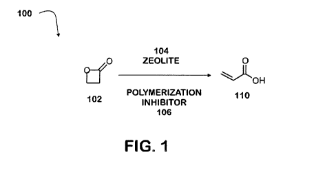
[078] In some aspects, provided is a method of producing acrylic acid from
beta-
propiolactone, by combining beta-propiolactone, a zeolite, and optionally a
polymerization inhibitor; and producing acrylic acid from at least a portion
of the beta-
propiolactone. For example, with reference to FIG. 1, process 100 is an
exemplary
process to produce acrylic acid. Beta- propiolactone 102 is combined with
zeolite 104
and polymerization inhibitor 106 to produce acrylic acid 110. In some
variations,
process 100 is performed neat. In other variations, process 100 is performed
in the
presence of a solvent. In some
embodiments, the method further includes
continuously isolating the acrylic acid produced. In some variations, the
acrylic acid is
isolated by distillation. In other aspects, provided herein are systems for
production of
acrylic acid. For example, with reference to FIG. 2, an exemplary acrylic acid
production system is depicted. System 200 is configured to produce acrylic
acid from
bPL, according to the methods described herein.
[079] System 200 includes reactor 210, configured to receive bPL, a zeolite,
and a
polymerization inhibitor, and to produce acrylic acid from at least a portion
of the bPL
according to the methods described herein. Reactor 210 is configured to
produce
acrylic acid at an elevated temperature. Any of the temperatures described
herein for
the methods may be employed in the system. For example, in one variation,
reactor
210 is configured to produce acrylic acid at a temperature between 170 C and
200 C.
Suitable reactors may include, for example, a Parr reactor.
21
CA 03018208 2018-09-18
WO 2017/165323
PCT/US2017/023269
[080] In some variations, reactor 210 is configured to control the rate of
addition of
one or more of the bPL, the zeolite, and the polymerization inhibitor added.
For
example, in one variation, a mixture of the bPL and the polymerization
inhibitor may
be slowly added using a control valve to a mixture of catalyst in a solvent.
[081] With reference again to FIG. 2, reactor 210 further includes vapor port
214. In
some variations, reactor 210 is configured to continuously strip off at least
a portion of
the acrylic acid produced, and vapor port 214 is configured to pass acrylic
acid vapors
to collection vessel 220.
[082] With reference again to FIG. 2, system 200 further includes acid/base
scrubber
230, configured to receive acrylic acid from collection vessel 220. In other
variations
of the system, acid/base scrubber 230 may be omitted. Further, with reference
to FIG.
2, elements 212, 216 and 222 are dip tubes.
[083] Fig. 3 presents the method of this invention in an arrangement suitable
for
commercial practice of the invention in a fixed bed configuration. A bPL feed
that may
optionally be admixed with a solvent enters the process via a line 312. A pair
of
reactors 310 and 312 each retaining multiple tubular beds of catalyst are
configured
to receive bPL from the feed line 312 at rate controlled by a feed pump 314 to
control
the rate of addition of bPL. The tubular form of reactor is preferred for
removing heat
from the catalyst bed during the reaction, but is not required and other types
of reactors
and arrangements may be used. In particular, the depiction of two reactors is
for
illustration purposes only and the process may use a single reactor or any
number of
reactors. Input line 316 may optionally supply additional process input
streams such
as diluents into admixture with the contents of line 324 to produce a reactor
input
stream 326.
22
CA 03018208 2018-09-18
WO 2017/165323
PCT/US2017/023269
[084] Reactor input stream 326 undergoes heating to produce a vapor phase feed
stream. A heat exchanger 320 supplies a heat input to reactor input stream
326. Heat
may be from an internal process stream or from an external heat source. The
heating
will be sufficient to insure that the reactor input stream is in a complete
vapor phase
before it enters reactor 326.
[085] The contents of the feed stream are converted at least in part to
acrylic acid in
reactor 310 and reactor 312. A transfer line 330 passes an intermediate stream
containing unconverted bPL and acrylic acid along with any additional input
materials
added with the bPL to reactor 312. An optional heat exchanger 332 may be added
to
control and adjust, typically by heat removal, the temperature of the
intermediate
stream before it enters reactor 312. An effluent stream 334 is recovered from
reactor
312. Reactor effluent stream 334 contains any unconverted bPL, acrylic acid
and any
additional input materials that may have been added to the reactor input
stream 326.
[086] Typically a product separation section (not shown) receives effluent
stream 334
to recover the acrylic acid product. Along with recovery of the acrylic acid
product the
separation section will in most cases also recover unconverted bPL (which is
usually
recycle) and the diluent and the other additive streams that may have been
added with
the feed and are still recoverable while also rejecting unwanted by-products.
[087] Fig. 4 presents the method of this invention in an arrangement suitable
for
commercial practice of the invention in a moving bed configuration. A reactor
vessel
410 houses an upper reaction section 412 that holds a bed of catalyst 416 and
a lower
reaction section 414 that holds a bed of catalyst 418, with both reactor beds
arranged
for radial flow of reactants across each reactions section.
[088] With respect to fluid flow reactor vessel 410 is configured to receive a
combined
bPL feed stream comprising bPL. A feed line 420 delivers a bPL feed and an
additive
23
CA 03018208 2018-09-18
WO 2017/165323
PCT/US2017/023269
line 426 delivers any additives for combination into a combined feed 422 that
passes
through a heater 424 that heats the combined feed to insure delivery of an all
vapor
phase combined feed stream to reactor section 412. The combined feed passes
through a heat exchange vessel 430 that is provided in some embodiments to
heat
catalyst that is entering reactor vessel 410 via a catalyst transfer line 450.
The
combined feed flows downward into an annular distribution space 432 that
distributes
it around catalyst bed 416. After the combined feed passes through bed 416 a
center
pipe 436 collects an upper reactor effluent comprising AA, unreacted combined
feed
and any remaining additives for transfer from the vessel into an inter-heater
440 via a
line 438. Inter-heater 440 raises the temperature of the first reactor section
effluent
and returns the heated upper reactor effluent passes to the lower reactor
section 414
via line 428. Annular space 442 distributes the heated upper reactor effluent
around
the lower catalyst bed 418. A lower reactor effluent passes through a center
pipe 444
and into annular space 446. A line 448 recovers the lower reactor effluent and
passes
it to facilities similar to those previously described for recovery of AA
product and
optional recycle of unconverted bPL, recovery of additives, and removal of by-
products.
[089] In this embodiment catalyst is periodically removed from the bottom of
reactor
vessel 410 by line 443 and replaced at the top of reactor vessel 410 by line
450.
Catalyst flows through the vessel by dropping from into line 460 from
collection pipes
452 that withdraw catalyst from the annular catalyst bed 418. As catalyst
drops from
bed 412, transfer pipes 454 add catalyst from catalyst bed 416 and distribute
around
catalyst bed 418. In turn as catalyst drops from catalyst bed 416, transfer
pipes 456
replace it with catalyst withdrawn from heat exchange section 458 of heat
exchanger
430 that receives fresh and/or regenerated catalyst from catalyst supply line
450.
24
CA 03018208 2018-09-18
WO 2017/165323
PCT/US2017/023269
[090] The reactor vessel may operate with or without continuous regeneration.
In the
latter case, deactivated or partially deactivated catalyst withdrawn by line
460 may be
discarded or transferred to remote regeneration facilities located on-site or
off-site for
reactivation and reuse of the spent catalyst. Line 450 will be used to supply
reactivated
or fresh catalyst to the reactor vessel 410 as catalyst is withdrawn vial line
460.
[091] In those embodiments that use continuous regeneration Fig. 4 shows
regeneration system 462 that receives at least partially deactivated catalyst
from
reaction vessel 420 via line 471 and returns reactivated, and optionally
treated catalyst
to to reactor vessel 410 via lien 450.
[092] In this embodiment the transfer of catalyst to the regeneration system
462
begins with the intermittent passage of catalyst to a lock hopper 464 through
line 443
upon the opening and closing of an upper control valve 460. Another control
valve 463
regulates the movement of catalyst from lock hopper 464 into a lift vessel
466. When
catalyst is ready for regeneration transfer through line 471, control valve
463 is closed
and lift gas enters lift vessel 470 via line 468 and is carried to the bottom
of lift vessel
466 by lift gas tube 470. The lift gas carries the catalyst upward into a
catalyst hopper
472 of regeneration system 462. Lift gas disengages from the catalyst in
vessel 472
and is removed from the regeneration section 479 by conduit 475.
[093] Catalyst is regenerated as it flows intermittently from the top to the
bottom of
regeneration system 462. Intermittent passage of catalyst begins with the
opening of
a valve 490 in a line 491 that results in catalyst from hopper 472 passing
downwardly
through a line 473 into an upper chamber 477 of a combustion vessel 476 as
catalyst
drops into a lower portion 488 of the combustion vessel 476 to replace
catalyst the
dropped into a lock hopper 492. Valve 491 isolates lock hopper 492 for
transfer of
catalyst into lift vessel 496. Catalyst is transported from lift vessel 496
into line 450 by
CA 03018208 2018-09-18
WO 2017/165323
PCT/US2017/023269
closing valve 494 and injecting lift gas into lift vessel 496 via line 447 in
the manner4
previously described.
[094] In various embodiment that regeneration system passes a regeneration gas
and may optionally pass one or more treatment and/or purge gases through the
regeneration section. A baffle 467 divides the combustion vessel into the
upper
chamber 477 and the lower chamber 488. The primary regeneration gas enters the
regeneration section 462 via a line 478 and passes into the bottom of upper
chamber
477, across a bed 482 of deactivation catalyst. A line 474 withdraws the
regeneration
gas from the top of upper chamber 477. Additional regeneration gas or
treatment gas
enter the bottom of lower chamber 488 via line 487. An additional gas stream,
typically
a treatment gas may also enter a lower contact zone 489 via a line 461. A line
479
withdraws gas from lower chamber 488 below baffle 467. Since lower contact
zone
489 communicates with combustion vessel 476, conduit 479 also withdraws gas
that
enter the lower contact zone 489.
[095] Fig. 5 presents the method of this invention in an arrangement suitable
for
commercial practice of the invention in a fluidized reaction configuration.
Fig. 5 shows
a fluidized reactor arrangement that uses a dilute phase transfer zone as the
catalyst
contact zone (also referred to as riser.) Fig. 5 shows a typical fluidized
reactor
arrangement 10 for fluidized catalyst contacting that is integrated with a
regeneration
zone. In the unit 10 a feed stream is contacted in reactor 12 with a
regenerated
conversion catalyst of this invention. In an embodiment, regenerated
conversion
catalyst entering from a regenerator conduit 18 contacts the bPL combined feed
stream comprising bPL and one or more of diluents fluidization gases, and
other
additives as herein described. In most embodiments the regenerated catalyst is
at
substantially higher temperature than the combined feed and additional heating
of the
26
CA 03018208 2018-09-18
WO 2017/165323
PCT/US2017/023269
feed by contact with the regenerated catalyst can provide additional
fluidization to lift
the catalyst and carry up the riser 20 of the reactor 12. The regenerator
conduit 18 is
in downstream communication with the regenerator 14. The riser 20 has an inlet
19 in
downstream communication with said regenerator conduit 18. The regenerator
conduit
19 is connected to the riser 20 at a lower end. A control valve located
between sections
18 and 19 of the regenerator conduit regulates the flow of catalyst out of the
regenerated catalyst conduit and provides a pressure drop that prevents any
substantial flow of the feed stream up the section 18 of the regeneration
conduit.
[096] In another aspect of the invention spent cracking catalyst entering from
a
recycle catalyst conduit 19 and a riser inlet tube 23 is contacted with the
combined
bPL feed stream riser 20 of the reactor 12 without the spent catalyst
undergoing
regeneration. Again a valve at the top of riser inlet tube 23 regulates the
flow of catalyst
through tube 23. In this aspect the spent catalyst recycle will allow
additional control
of the temperature and/or the activity of the catalyst in the reactor 12 and
can increase
the coke concentration of catalyst in the reactor 12 to aid in the regulation
of
regenerator temperatures and catalyst regeneration.
[097] The recycle of spent catalyst through the recycle catalyst conduit can
also be
used to increase the ratio of catalyst-to-feed in the reactor. In one
embodiment the
catalyst-to-feed weight ratio is in a range between 5 and 20 and preferably
between
and 15. In some embodiments portions of the bPL feed may be fed to the riser
20
through elevated distributors 16 and this can be used to maintain conversion
of the
bPL as the catalyst passes up the riser 20.
[098] The recycle conduit 19 is in downstream communication with a riser
outlet 25.
The recycle conduit 19 is connected to the riser 20 at the outlet end of the
recycle
conduit by riser tube 23. The recycle conduit 19 bypasses the regenerator 14
by being
27
CA 03018208 2018-09-18
WO 2017/165323
PCT/US2017/023269
in downstream communication with the riser outlet 25 and the riser tube 23
being in
direct, downstream communication with the recycle conduit. Consequently, spent
catalyst entering the recycle conduit 19 passes back to the riser 20 before
any of it
enters the regenerator 14. The recycle conduit 19 has no direct communication
with
the regenerator 14.
[099] The AA containing product gases and spent catalyst in the riser 20 are
thereafter discharged from the riser outlet 25 into a disengaging chamber 27
which
contains the riser outlet. The gas stream containing AA product is disengaged
from
the catalyst in the disengaging chamber 27 using a rough cut separator 26.
Cyclonic
separators which may include one or two stages of cyclones 28 in the reactor
vessel
22 further separate catalyst from AA products. Product containing gases exit
the
reactor vessel 22 through an outlet 31 for transport to downstream product
separation
facilities to recover AA, recycle bPL, diluents and additives. In another
embodiment,
the recycle conduit 19 and the regenerator conduit 18 are in downstream
communication with the disengaging chamber 27. The outlet temperature of the
product containing gas leaving the riser 20 should be less than 325 C and
preferably
less than less than 300 C.
[100] After separation from product containing gases catalyst falls into a
stripping
section 34 where an inert gas is injected through a nozzle 35 and distributed
to purge
any residual product vapor or gas. After the stripping operation, a portion of
the spent
catalyst is fed to the catalyst regenerator 14 through a spent catalyst
conduit 36. The
catalyst regenerator 14 may be in downstream communication with the riser 20,
specifically, the riser outlet 25. In certain embodiments a portion of the
spent catalyst
is recycled through recycle catalyst conduit 19 to the riser 20 as previously
described.
28
CA 03018208 2018-09-18
WO 2017/165323
PCT/US2017/023269
[101] Fig. 5 depicts a vessel 14 for the regeneration of catalyst having a
cornbustor
41 as the primary zone for the regeneration of the catalyst by combustion of
the coke
and the displacement of other volatile compounds from the surface of the
catalyst.
Other embodiments of the invention may use other configurations and
arrangement of
regenerators. In the catalyst regenerator 14, a stream of oxygen-containing
gas, such
as air, is introduced from line 37 through a distributor 38 to contact the
coked catalyst,
burn coke deposited thereon, and provide regenerated catalyst and a gas stream
comprising the products of the combustion and generally referred to as flue
gas.
Catalyst and air flow upwardly together through the combustor 41 and along a
combustor riser 40 located within the catalyst regenerator 14. The catalyst
which is at
least partially regenerated is discharged through a disengager 42 to effect an
initial
separation of the catalyst from the flue gas. A series of cyclonic separation
steps in
cyclones 44 and 46 effect further separation of regenerated catalyst and flue
gas. The
cyclones direct the catalyst separated therein into the conduits that extend
downwardly
from the cyclones and are referred to as diplegs. The flue gas which is
relatively free
of catalyst exits cyclones 44, 46 and flows out of the regenerator vessel 14
through
line 48. Regenerated catalyst is recycled back to the reactor riser 20 through
the
regenerated catalyst conduit 18.
[102] The flue gas will typically contain carbon dioxide, water vapor, and
lesser
amounts of carbon monoxide. Depending on the type and the erosion properties
of the
catalyst the flue gas may also contain small amounts of extremely fine
catalyst
particles typically in the range of between .2 and 2 micrometers which in some
applications will require additional treatment of the flue gas for removal of
such
particles.
29
CA 03018208 2018-09-18
WO 2017/165323
PCT/US2017/023269
[103] The acrylic acid produced according to the methods described herein may
be
used for various applications. For example, acrylic acid may be used to make
polyacrylic acid for superabsorbent polymers (SAPs). The SAPs find use in
diapers,
adult incontinence products, and feminine hygiene products among other things.
[104] In some aspects, provided is a method for producing a superabsorbent
polymer, by: polymerizing the acrylic acid produced according to any of the
methods
described herein in the presence of a cross-linker to produce the
superabsorbent
polymer.
EXAMPLES
[105] The following Examples are merely illustrative and are not meant to
limit any
aspects of the present disclosure in any way.
Example 1 - Conversion of bPL to acrylic acid using a zeolite
[106] This Example demonstrates the production of acrylic acid from bPL using
a
zeolite.
[107] A mixture of bPL (3.0 g) and phenothiazine (9.0 mg) was added using a
needle
value to a mixture of sulfolane (40.0g) and Zeolite Y hydrogen (20.0 g) at 165
C with
50 psi of carbon monoxide. Zeolite Y hydrogen (80:1 mole ratio SiO2/A1203,
powder
S.A. 780 m2/g) was dried under vacuum at 100 C for one day before use.
Phenothiazine was the polymerization inhibitor used. Sulfolane was the solvent
used,
and was dried over 3A molecular sieves prior to use. The bPL was added slowly
using
the needle valve over about 8.6 minutes. The reaction mixture was heated to
170 C
to produce acrylic acid.
[108] The reaction was monitored by infrared spectroscopy (IR). The reaction
was observed to be completed after about 3 hours, when no bPL was detectable
by IR. The zeolite was then filtered off from the reaction mixture, and a
sample of
CA 03018208 2018-09-18
WO 2017/165323
PCT/US2017/023269
the resulting mixture was dissolved in deuterium (D20) and chloroform (0D013)
for
nuclear magnetic resonance (N MR) analysis. The observed vinyl peaks between
5.80 and 6.47 ppm in the 1H NMR confirmed the production of acrylic acid.
Example 2 - Vapor phase conversion of bPL to acrylic acid using a H-ZSM5
[109] Vapor phase conversion of 13-propiolactone to acrylic acid was performed
in
packed-bed reactor using H-ZSM-5 (ACS Materials LLC, Si:A1=38, diameter 2mm,
surface area >=250 m2/g) as a catalyst. 11 grams of H-ZSM-5 catalyst were
loaded
into jacketed stainless steel 316 pipe reactor (ID 0.5 inch), the catalyst was
supported
between glass beads columns (stainless steel wool was placed below and above
glass beads). Multi point thermocouple was inserted through the center of the
reactor
and hot oil was circulated through the reactor jacket to maintain the desired
reactor
temperature. bPL was fed to the reactor by means of saturator: N2 at the rate
of 28
g/hr was flown into the bottom of the vessel containing liquid bPL at a=94 C,
this
resulted in bPL feed rate of 5 g/hr. The pressure of reactor and saturator was
maintained at 9.5 psig. The reaction products were absorbed in chilled to 10 C
dichloromethane and the solution of reaction products in dichloromethane was
analyzed by gas chromatography. The line between the saturator and the reactor
as
well as the line between the reactor and absorber were heat traced to prevent
condensation of bPL and acrylic acid. The reaction was conducted at the
reactor
temperature of 210 C. At this conditions bPL conversion of greater than 99.9%
was
observed with selectivity of acrylic acid product of greater than 98% (WHSV at
these
conditions was 0.45 h-1).
31