Note: Descriptions are shown in the official language in which they were submitted.
CA 03018220 2018-09-18
WO 2017/172777 PCT/US2017/024553
- 1 -
ADJUSTABLE SUPPORT GARMENT WITH HARNESS SYSTEM
FIELD OF THE INVENTION
The present invention relates to a garment having adjustable support provided
by harness features.
BACKGROUND OF THE INVENTION
Conventional support garments, such as bras, often lack features that enable a
wearer to customize the amount of support provided by the bra. Further, when
features such
as hook closures or strap adjustment features are provided, they are often
difficult for the
wearer to access or may not be intuitive to use.
BRIEF DESCRIPTION OF THE DRAWING
The present aspects are described in detail below with reference to the
attached drawing figures, wherein:
FIG. 1 depicts a rear view of a bra having adjustable support provided by a
harness system, in accordance with an aspect herein;
FIG. 2 depicts an enlarged view of the bra of FIG. 1, in accordance with an
aspect herein;
FIG. 3 depicts a side view of the bra of FIG. 1, in accordance with an aspect
herein;
FIG. 4 depicts a front, perspective view of the bra of FIG. 1, in accordance
with an aspect herein;
FIG. 5 depicts a front, perspective view of the bra of FIG. 1 with a portion
of
the bra body removed, in accordance with an aspect herein;
FIG. 6 depicts a side view of the bra of FIG. 1 with a portion of the bra body
removed, in accordance with an aspect herein;
FIG. 7 depicts another side view of the bra of FIG. 1 with a portion of the
bra
body removed, in accordance with an aspect herein;
FIG. 8 depicts an internal view of the left side of the bra of FIG. 1, in
accordance with an aspect herein;
CA 03018220 2018-09-18
WO 2017/172777 PCT/US2017/024553
- 2 -
FIG. 9 depicts an overhead view of the bra of FIG. 1, in accordance with an
aspect herein;
FIG. 10 depicts a front view of a left liner cup of the bra of FIG. 1, in
accordance with an aspect herein;
FIG. 11 depicts a cross section of the left liner cup of FIG. 10, in
accordance
with an aspect herein;
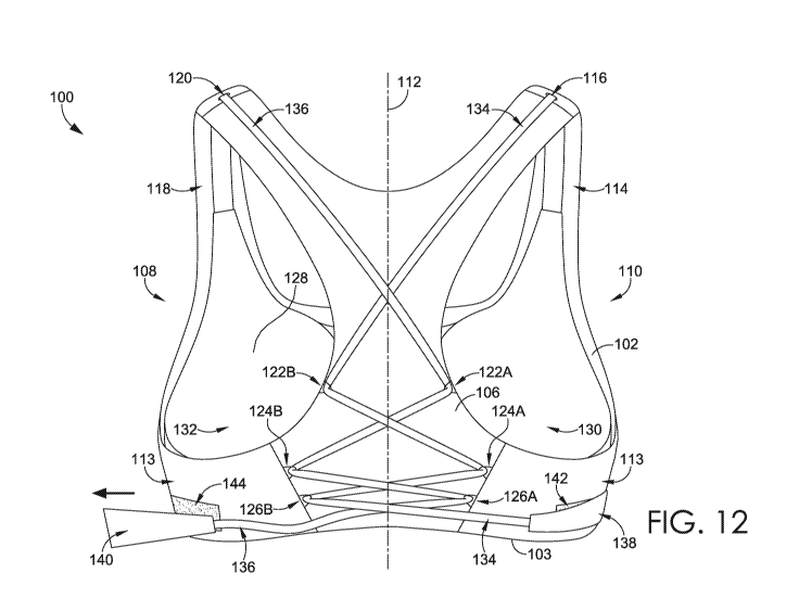
FIG. 12 depicts a rear view of the bra of FIG. 1 with a left harness strap in
a
detached position, in accordance with an aspect herein;
FIG. 13 depicts a front view of the bra of FIG. 1 with a left harness strap in
a
detached position, in accordance with an aspect herein;
FIG. 14 depicts a side view of the bra of FIG. 1 with a left harness strap in
a
detached position, in accordance with an aspect herein;
FIG. 15 depicts a front, perspective view of the bra of FIG. 1 with a left
harness strap in a partially attached position, in accordance with an aspect
herein;
FIG. 16 depicts a rear view of a bra having adjustable support provided by a
harness system, in accordance with an aspect herein; and
FIG. 17 depicts a front, perspective view of the bra of FIG. 16, in accordance
with an aspect herein.
DETAILED DESCRIPTION OF THE INVENTION
Present aspects described herein are intended in all respects to be
illustrative
rather than restrictive. Alternative aspects will become apparent to those of
ordinary skill in
the art to which the present aspects pertain without departing from its scope.
From the
following, it will be seen that aspects herein are well adapted to attain all
the ends and objects
set forth above, together with other advantages that are obvious and inherent.
It will be
understood that certain features and subcombinations are of utility and may be
employed
without reference to other features and subcombinations. This is contemplated
by and is
within the scope of the claims.
An adjustable support harness system utilized in a garment, such as a bra, is
provided herein. The adjustable support harness system, as utilized in a bra,
for example,
includes a pair of harness straps, which are coupled to a liner or a cup liner
at one end and to
a tab structure (e.g., a tab) at the opposite end. Each of the harness straps
are configured to
CA 03018220 2018-09-18
WO 2017/172777 PCT/US2017/024553
- 3 -
be fed through an aperture or opening in a corresponding right or left strap
of the body of the
garment. These openings are sized to allow the harness straps to slide through
said openings
and maintain the placement and orientation of the harness straps during
adjustment, in some
aspects. The harness straps are then laced through a series of maintainers or
fittings that are
integrated with or coupled to the exterior of a back portion of the garment. A
maintainer may
be an integrally formed structure or fitting of the bra body or may be an
external structure or
fitting that is coupled to the bra body, in aspects. Exemplary maintainers may
include a loop,
ring, a d-ring, a hook, a lace hook, a slide, a grommet, an eyelet, an
adjuster slide, an
aperture, an opening, and/or a clasp. Exemplary maintainers may include
materials that
exhibit a degree of rigidity so as to maintain an eye, an opening, or a loop-
like shape in a
resting state. The configuration of the series of maintainers may help to
reduce collapse of
the bra body shoulder straps during adjustment.
In order to adjust the garment using the adjustable support harness system,
the
tabs may be pulled or manipulated to tighten or loosen each of the harness
straps, which in
turn adjusts the liner at the other end of the harness straps. The tabs are
generally pulled from
the back of the body, wrapped around the sides of the body, and are affixed at
or near the
front and/or sides of the body. However, it will be understood by those having
skill in the art
that the tabs may be accessible at or near the front and/or sides of the bra
body for
convenience in adjustment.
Because of the interconnection between the liner, harness straps, openings in
the shoulder straps, and maintainers, a wearer can adjust the fit of the
harness straps, a level
of back or posture support, and/or the degree of lift of the liner with a
single manipulation of
the tab of the adjustable support harness system. Additionally, the harness
system may be
configured to provide a same-side adjustment. For example, the right harness
strap and a first
section of the liner are adjusted by manipulating a right tab, while the fit
and support of the
left harness strap and a second section of the liner is similarly adjusted by
manipulating a left
tab. The same-side adjustment feature reduces confusion for a wearer and
improves the ease
in which the harness system may be adjusted. Alternatively, the harness system
may be
configured to provide an opposite-side adjustment. For example, the right
harness strap and
the first section of the liner may be adjusted by manipulating a left tab,
while the fit and
support of the left harness strap and the second section of the liner may be
adjusted by
manipulating a right tab. Although a same-side adjustment feature is provided
in the
exemplary figures of this disclosure, these figures should not be construed as
limiting the
CA 03018220 2018-09-18
WO 2017/172777 PCT/US2017/024553
- 4 -
disclosure to a same-side adjustment feature, as an opposite-side adjustment
feature may be
used and is considered to be within the scope of this disclosure.
For simplicity, a bra or bra-type garment is described herein. However, the
discussion of the adjustable harness system as useable with a bra should not
be construed as
limiting, and other clothing or garments are considered to be within the scope
of the
disclosure. Exemplary garments that use the adjustable harness system
described herein may
include a camisole, a shirt, a tank top, a blouse, a bralette, a dress, and
swimwear, for
example. Accordingly, it will be understood that the adjustable harness system
may be used
with relation to other garments and the examples provided by the figures
herein are merely
illustrative in nature.
Additionally, it will be understood that, generally, directional descriptions
used herein, such as left or right, front or back, up or down, are used
relative to basic
anatomical convention in order to provide consistency and alleviate confusion
in the
description of the adjustable support harness system when shown from the
various vantage
points provided in the figures herein. As an example, directional descriptions
are used with
respect to the garment being in an as-worn configuration with the wearer
standing in the
anatomical position.
Accordingly, in one aspect, an article of apparel is provided. The article
comprises a body. The body comprises at least a front portion and a back
portion, each
having a lower margin, in one aspect. The body also comprises a first side
with respect to a
hypothetical midline axis that bisects the body into generally equal right and
left halves, in
some aspects. And the body further comprises a second side with respect to the
hypothetical
midline axis, in one aspect. The body comprises a first shoulder strap having
a first aperture
and a second shoulder strap having a second aperture, in aspects. The back
portion of the
body comprises at least a first pair of maintainers, in some aspects, such
that each maintainer
is positioned opposite the other maintainer with respect to the hypothetical
midline axis. In
further aspects, the back portion comprises a second pair of maintainers. In
one further
aspect, each of the maintainers of the first pair of maintainers is attached
to the back portion
at a first distance from the hypothetical midline axis, and each maintainer of
the second pair
of maintainers is attached to the back portion at a second distance from the
hypothetical
midline axis, wherein the second distance is greater than the first distance.
And in some
further aspects, the back portion further comprises a third pair of
maintainers, wherein a first
lengthwise distance, as measured along the hypothetical midline axis, between
the first pair
CA 03018220 2018-09-18
WO 2017/172777 PCT/US2017/024553
- 5 -
of maintainers and the second pair of maintainers is greater than a second
lengthwise distance
between the third pair of maintainers and the second pair of maintainers.
Continuing, the article further comprises a liner, in aspects. The liner is
positioned adjacent and internal to the body, in aspects. In some aspects, at
least a portion of
the liner is coupled to the front portion of the body. The liner has a first
harness strap and a
second harness strap, in some aspects. In one aspect, the first and second
harness straps are
positioned adjacent to the first and second shoulder straps. In some aspects,
the first harness
strap is adapted to pass through the first aperture and at least one
maintainer of the first pair
of maintainers. In one aspect, the first harness strap has a terminally
located first tab. In
some aspects, the second harness strap is adapted to pass through the second
aperture and at
least one maintainer of the first pair of maintainers, and further has a
terminally located
second tab. In aspects, the first side of the body includes a first attachment
element to which
the first tab is adapted to be attached and the second side includes a second
attachment
element to which the second tab is adapted to be attached. In further aspects,
the first
attachment element and the second attachment element are located proximate to
the lower
margin. The first attachment element and the second attachment element, in
some aspects,
include one or more fasteners useable for removeably attaching to the first
tab and the second
tab, respectively. In one aspect, the liner further comprises a first support
pad and a second
support pad, the first support pad and second support pad extending inwardly
from a surface
plane of the liner. In one further aspect, the first and second support pads
are embedded
between two or more layers of material of the liner.
Another aspect provides for a garment having adjustable support provided by
a harness system. The garment comprises a body. In one aspect, the body
comprises, at
least, a front portion, a first side with respect to a hypothetical vertical
midline axis, and a
second side with respect to the hypothetical vertical midline axis. The body
also comprises,
in one aspect, a first shoulder strap having a first aperture and a second
shoulder strap having
a second aperture. The body comprises a back portion, in aspects. The back
portion of the
body comprises, at least, a first set of maintainers and a second set of
maintainers. In some
aspects, each set of maintainers having, at least, a first side maintainer and
a second side
maintainer. In such aspects, the first side maintainer may be attached to the
back portion
opposite a second side maintainer also attached to the back portion with
respect to the
hypothetical vertical midline axis. And, in some aspects, the first set of
maintainers is
attached to the back portion above the second set of maintainers, with respect
to a lower
CA 03018220 2018-09-18
WO 2017/172777 PCT/US2017/024553
- 6 -
margin of the body. In one further aspect, the first set of maintainers is
attached to the back
portion at a first lengthwise distance from the lower margin as measured along
the
hypothetical vertical midline axis, and wherein the first lengthwise distance
facilitates
distribution of tensional forces during adjustment. In one aspect, each
maintainer of the
second pair of maintainers is positioned at one or more seam lines. The
garment further
comprises a liner. In one aspect, the liner is attached to an interior surface
of the body at one
or more locations. In some aspects, the liner has a first section and a second
section. The
first section of the liner comprises a first harness strap and the second
section of the liner
comprises a second harness strap, in some aspects. In a further aspect, the
first section and
the second section of the liner are attached to the interior of the front
portion of the body at
one or more locations. In one aspect, the first harness strap is adapted to
pass through the
first aperture, cross the hypothetical vertical midline axis, and sequentially
pass through at
least one maintainer of the first set of maintainers and at least one
maintainer of the second
set of maintainers. In a further aspect, the first harness strap terminates in
a right tab. In one
aspect, the second harness strap is adapted to pass through the second
aperture, cross the
hypothetical vertical midline axis, and sequentially pass through at least one
maintainer of the
first set of maintainers and at least one maintainer of the second set of
maintainers. In a
further aspect, the second harness strap terminates in a second tab. The first
side of the body
includes a first attachment element to which the first tab is adapted to be
attached, and the
second side of the body includes a second attachment element to which the
second tab is
adapted to be attached, in aspects. The attachment of the first tab to the
first attachment
element shifts the first section of the liner from a first support position to
a second support
position, and the attachment of the second tab to the second attachment
element shifts the
second section of the liner from a first support position to a second support
position, in
aspects. And in one aspect, each of the first and second sections of the liner
include at least a
first zone and a second zone, the first zone having a first molding
characteristic and the
second zone having a second molding characteristic different than the first
molding
characteristic. In such an aspect, the first molding characteristic has a
reduced modulus of
elasticity relative to the second molding characteristic, for example.
Additionally or
alternatively, in one aspect, the first zone and the second zone are formed
from the same one
or more materials. In one aspect, the first zone is located superior to the
second zone with
respect to the lower margin.
CA 03018220 2018-09-18
WO 2017/172777 PCT/US2017/024553
- 7 -
In yet another aspect, an article of apparel having adjustable support
provided
by a harness system is provided. The article comprises a body. The body
comprises, at least,
a front portion, a first side with respect to a hypothetical vertical midline
axis, and a second
side with respect to the hypothetical vertical midline axis, in aspects. The
body further
comprises a first shoulder strap coupled to the front portion, the first
shoulder strap having a
first aperture adjacent to where the first shoulder strap is coupled to the
front portion, in one
aspect. And, in one aspect, the body comprises a second shoulder strap coupled
to the front
portion, the second shoulder strap having a second aperture adjacent to where
the second
shoulder strap is coupled to the front portion. In aspects, the body comprises
a back portion,
and the back portion comprises at least a first pair of maintainers, a second
pair of
maintainers, and a third pair of maintainers. In one aspect, each pair of
maintainers has a first
maintainer placed opposite a second maintainer with respect to the
hypothetical vertical
midline axis. In some aspects, with respect to a lower margin of the body, the
first pair of
maintainers is positioned superior to the second pair of maintainers and the
second pair of
maintainers is positioned superior to the third pair of maintainers. The
article further
comprises a liner having a first section and a second section. In one aspect,
each of the first
and second sections comprise at least a first zone and a second zone, the
first zone having
greater elasticity than the second zone. The first section of the liner
further comprises, in one
aspect, a first harness strap extending from the first zone of the first
section. And the first
harness strap is adapted to pass through the first aperture and sequentially
pass through at
least one maintainer of the first, second, and third pairs of maintainers,
wherein the first
harness strap passes between the first side and the second side an even number
of times, in
some aspects. The first harness strap terminates at a first tab, in one
aspect. The second
section of the liner further comprises a second harness strap extending from
the first zone of
the second section, in aspects. In one aspect, the second harness strap is
adapted to pass
through the second aperture and sequentially pass through at least one
maintainer of the first,
second, and third pairs of maintainers, wherein the second harness strap
passes between the
first side and the second side an even number of times. In some aspects, the
second harness
strap terminates at a second tab. In some aspects, the first side of the body
further comprises
a first attachment element to which the first tab is adapted to be attached.
And in some
aspects, the second side of the body further comprises a second attachment
element to which
the second tab is adapted to be attached. Attachment of the first tab to the
first attachment
element shifts the first section of the liner from a first support position to
a second support
CA 03018220 2018-09-18
WO 2017/172777 PCT/US2017/024553
- 8 -
position, and attachment of the second tab to the second attachment element
shifts the second
section of the liner from a first support position to a second support
position, in aspects.
With reference now to FIG. 1, a rear view of a support garment such as a bra
having an adjustable support harness system is provided in accordance with an
aspect herein.
As illustrated in FIG. 1, the bra 100 comprises a bra body 102 that acts as an
exterior barrier,
outer layer, and/or shell structure of the bra 100. In some aspects, the bra
body 102 provides
a support structure for stabilizing the harness system components during
adjustment of the
bra 100. As will be understood, the term "bra body" should not be construed as
limiting, as a
body of any garment type is capable of having the adjustable support harness
system as
described herein and is considered to be within the scope of this disclosure.
A body might
refer to one or more fabric panels of a camisole, a shirt, a tank top, or a
dress, for example. In
one exemplary aspect, the bra body 102 may include one or more panels of
fabric and/or
material. In another exemplary aspect, the bra body 102 may be constructed
using a
continuous panel of fabric to provide a seamless or nearly seamless garment.
In one aspect, the bra body 102 comprises one or more panels of a fabric
having at least one of a compression characteristic, a moisture wicking
capability, and/or a
coating that increases the rigidity of the bra body fabric. As used herein,
exemplary
compression characteristics may include a modulus of elasticity (e.g., a
measurement of a
material or substance's resistance to elastic non-permanent deformation),
wherein as the
modulus increases, the amount of elasticity provided by a material decreases.
Materials
having an increased or high modulus of elasticity may provide for a "lockdown"
characteristic that reduces or minimizes elasticity and increases support of
the structure.
Exemplary materials having a high or increased modulus of elasticity include
polyester,
cotton duck, twill, and linen. Exemplary materials having a low modulus of
elasticity include
elastane and some jersey fabrics. One or more of the materials may be coated
or treated with
polyurethane (PU), thermoplastic polyurethane (TPU), silicone, and the like,
for example, in
order to increase the modulus of elasticity of one or more portions of a
garment. It will be
understood that compression capabilities may help to reduce unwanted upward
bounce of
breast tissue when the bra 100 is in an as-worn configuration, and further,
that additional
rigidity may provide strength and durability to the bra 100 structure.
Generally, the bra body 102 includes a front portion 104 (see, e.g., front
portion 104 in FIG. 13) and a back portion 106. When the bra 100 is in an as-
worn
configuration, the front portion 104 corresponds to a ventral side (e.g.,
anterior) of a wearer
CA 03018220 2018-09-18
WO 2017/172777 PCT/US2017/024553
- 9 -
of the bra 100. As will be apparent, the ventral side of a wearer may
generally include the
clavicle area, the front torso, and breast tissue, for example. And, in the as-
worn
configuration, the back portion 106 corresponds to a dorsal side (e.g.,
posterior) of a wearer
of the bra 100. The dorsal side of a wearer may include, for instance, the
rear shoulder area
including the scapulae, and the rear torso, for example. As described herein,
the front portion
104 is a front-facing portion of the bra body 102 when in an as-worn
configuration, in one
aspect. Additionally or alternatively, the back portion 106 is a rear-facing
portion of the bra
body 102.
The bra body 102 further comprises a first side or a "left" side 108 and a
second side or "right" side 110. In one embodiment, the right side 110 and the
left side 108
correspond to opposite sides of the bra body 102, with respect to a
hypothetical midline axis
112. It will be understood that the hypothetical midline axis 112 is an
imaginary or
hypothetical line that generally bisects the bra body 102 into equal right and
left halves, or
equal first and second halves. The hypothetical midline axis 112 may run in a
vertical
direction, from a lower margin 103 of the bra body 102 in an upward direction
towards straps
(as will be described hereinafter) of the bra body 102, for example. The lower
margin 103
refers to an edge or boundary of the bra 100 located opposite the right and
left shoulder straps
114 and 118. As used herein, the terms shoulder straps and body straps are
used
interchangeably. The midline axis 112 is referred to herein to provide a
simplified and clear
description of the bra body 102 structure. It will further be understood that
the midline axis
112 is generally parallel to or corresponds with a sagittal plane of common
anatomical
convention. Therefore, it will be understood by those in the relevant field
that, in the as-worn
configuration, the left side 108 of the bra body 102 corresponds to the left
side of a wearer
and the right side 110 of the bra body 102 corresponds to the right side of a
wearer. It will be
understood that the directional terms "left" and "right" are used
conventionally herein for
simplicity but may be used interchangeably with numerical terms such as first
and second, for
example.
In aspects, the bra body 102 includes a right underarm area 111 and a left
underarm area 113, with the left side 108 including the left underarm area 113
and the right
side 110 including the right underarm area 111. An underarm area may be
located between
the front portion 104 and the back portion 106. In one aspect, an underarm
area bridges or
spans the bra body 102 where the front portion 104 transitions into the back
portion 106. In
one aspect, an underarm area generally refers to a portion of the bra body 102
structure that
CA 03018220 2018-09-18
WO 2017/172777 PCT/US2017/024553
- 10 -
corresponds to and generally is located underneath an opening configured to
receive an
appendage (e.g., an arm) of a wearer when the bra 100 is in an as-worn
configuration. For
example, at FIG. 3, a side view of the bra of FIG. 1 is presented in
accordance with an aspect
herein, with a left underarm area 113 clearly illustrated. With respect to the
midline axis 112,
an underarm area may be positioned to the right and/or left outermost position
relative to the
midline axis 112 as allowed by the bra body 102 structure itself.
In a further aspect, the left underarm area 113 is defined by a left lateral
edge
115 of the bra body 102. The left lateral edge 115 forms an edge of the left
side 108 of the
bra body 102. The left lateral edge 115 generally corresponds to at least a
portion of an edge
along, or forming, an opening that accommodates the left arm when the bra 100
is in an as-
worn configuration. Similarly, the right underarm area 111 is defined by a
right lateral edge
117 of the right side 110 of the bra body 102, in one aspect. The right
lateral edge 117
corresponds to at least a portion of an edge along, or forming, an opening
configured to
receive the right arm when the bra 100 is in an as-worn configuration, for
example. The term
"lateral" is used herein with respect to the midline axis 112.
With continued reference to FIG. 1, the bra body 102 includes a right shoulder
strap 114 with a first aperture 116 and a left shoulder strap 118 with a
second aperture 120.
The right shoulder strap 114 is placed on the right side 110 of the bra body
102, and the left
shoulder strap 118 is placed on the left side 108 of the bra body 102, with
the right and left
shoulder straps 114 and 118 being non-adjustable straps, in one exemplary
aspect.
Alternatively, the right and left shoulder straps 114 and 118 may comprise
adjustable straps.
In another aspect, where each of the right and left shoulder straps 114 and
118 include
distinct front and back sections connected to one another, at least a portion
of the right and
left shoulder straps 114 and 118 may be adjustable, for example, by tightening
the adjustable
section with a slide. The right and left shoulder straps 114 and 118 run from
the front portion
104 to the back portion 106 in order to connect the front portion 104 to the
back portion 106.
As such, the front portion 104 may be coupled to at least a first end of the
right shoulder strap
114 and at least a first end of the left shoulder strap 118, while in a
further aspect, the back
portion 106 may be coupled to at least a second end of the right shoulder
strap 114 and at
least a second end of the left shoulder strap 118.
In some aspects, the first aperture 116 of the right shoulder strap 114 and
the
second aperture 120 of the left shoulder strap 118 may comprise openings in
the fabric and/or
materials comprising the right and left shoulder straps 114 and 118 of the bra
body 102.
CA 03018220 2018-09-18
WO 2017/172777 PCT/US2017/024553
- 11 -
Exemplary openings may comprise a slit-type opening, an oval-shaped opening, a
circular
opening, and/or any shape or type of opening (e.g., an eyelet, a buttonhole, a
grommet) that is
configured to accommodate and position a harness strap used for adjusting the
bra 100, as
will be described hereinafter. The first aperture 116 and second aperture 120
may be created
with any number of exemplary manufacturing techniques, for example, laser-
cutting and die
cutting. In another aspect, the first aperture 116 and second aperture 120 are
formed by gaps
in the weave or knit of the fabric and/or materials of the bra body 102. It
will be understood
that any number and kind of apertures may be present in the right and left
shoulder straps 114
and 118 and as such are considered to be within the scope of this disclosure.
The first aperture 116 and the second aperture 120 are generally positioned
near the first ends of the right and left shoulder straps 114 and 118. To put
it another way,
the first aperture 116 and the second aperture 120 may be positioned nearer
the front portion
104 than the back portion 106. In other exemplary aspects, the first and
second apertures 116
and 120 may be positioned nearer the back portion 106 than the front portion
104, or at an
intermediate or midway position between the front portion 104 and the back
portion 106. In
one example, the first aperture 116 and the second aperture 120 may be
positioned at similar
locations on the right and left shoulder straps 114 and 118, although they may
also assume a
staggered orientation with respect to one another such that one aperture is
positioned nearer
the front portion 104 than the other aperture.
In some aspects, the first aperture 116 may be located at an apex and/or
within
an apex region of the right shoulder strap 114. The placement of an aperture
within an apex
region of a corresponding strap may stabilize and retain a harness strap
during adjustment of
the bra 100 via the adjustable support harness system. Generally, an apex
region refers to an
area of a strap that corresponds to the shoulder top of a wearer when the bra
100 is in an as-
worn configuration with the apex region determined vertically with respect to
the midline
axis 112. For example, an apex and/or apex region may refer to a portion of a
corresponding
strap that connects the front portion 104 to the back portion 106 such that
when the bra 100 is
in an as-worn configuration, the apex and/or apex region of a corresponding
strap is generally
configured to contact and/or "rest" upon a wearer's shoulders. Similarly, the
second aperture
120 may be placed at an apex and/or within an apex region of the left shoulder
strap 118.
In exemplary aspects, the back portion 106 of the bra body 102 may comprise
one or more pair of maintainers configured to receive and retain harness
straps for adjusting
the bra 100 using the adjustable support harness system. To put it another
way, a maintainer
CA 03018220 2018-09-18
WO 2017/172777 PCT/US2017/024553
- 12 -
is a feature useable to anchor a harness strap to the bra body 102. As used
herein, a
"maintainer" may be any structure or fitting, integrated with or coupled to
the bra body 102,
that redirects a tensional force, such as a force applied by or to a harness
strap. In one
example, a maintainer may take the form of an aperture in the bra body 102 or
a fabric panel
thereof through which a harness strap may be passed. In another example, a
maintainer may
comprise a length of material having two terminal ends that are each attached
to the bra body
102, such that a harness strap, for example, may be passed under a remaining
unattached
portion of the material. In some aspects, the maintainers may be permanently
attached or
non-permanently attached to the bra body 102. Examples of attachment include
use of
adhesives, heat bonding, stitching, embedding between fabric layers, and/or
knotting.
The maintainers described herein may form one or more sets of maintainers,
one or more pairs of maintainers, and/or a combination thereof. As will be
understood, the
back portion 106 may include one or more maintainers, one or more pairs of
maintainers, one
or more sets of maintainers, or a combination thereof, such that the number,
placement,
location, type, or kind of maintainers depicted in the illustrative figures
herein are examples
only and should not be construed as limiting. For example, although three
pairs of
maintainers are depicted in FIG. 1, it will be understood that the bra 100 may
include only
one pair of maintainers, for example.
In one aspect, the back portion 106 includes a first pair of maintainers. In a
further aspect, the back portion 106 additionally includes a second pair of
maintainers. In yet
a further aspect, the back portion 106 also includes a third pair of
maintainers. Generally, a
pair of maintainers comprises a right maintainer that corresponds to the right
side 110 and a
left maintainer that corresponds to the left side 108. In one aspect, the
first pair of
maintainers includes a right maintainer 122A and a left maintainer 122B, the
second pair of
maintainers includes a right maintainer 124A and a left maintainer 124B, and
the third pair of
maintainers includes a right maintainer 126A and a left maintainer 126B, as
shown in FIG. 1.
Generally, a right maintainer is placed opposite a left maintainer with
respect to the midline
axis 112.
The bra 100 further includes a liner or cup liner 128, as shown in FIG. 1. As
used herein, the term "cup liner" should not be construed as limiting, but
rather is merely
descriptive of a particular aspect of the adjustable harness system as used in
the bra 100
pictured. However, it will be understood that the liner (e.g., cup liner) may
not include
separate or distinct bra-type cups, but rather, may be a continuous or molded
liner form that
CA 03018220 2018-09-18
WO 2017/172777 PCT/US2017/024553
- 13 -
provides bust support, for example. As used herein, the term "cup" refers to a
structure that
provides support for breast tissue and the term is not limited to the plain
and ordinary
meaning. And it will be understood that a liner of the adjustable harness
system may be
included in other garments such as shirts and swimwear, for example, to
provide bust support
with or without distinct cup forms. As such, the terms "cup" and "cup liner"
may be used
interchangeably with section, panel, portion, or half, for example, to refer
to part of the liner.
The cup liner 128 includes a right harness strap 134 coupled to a right liner
cup 130 and a left harness strap 136 coupled to a left liner cup 132. In some
aspects, each
harness strap may be coupled to a respective first section or second section
of a liner, for
example. The right and left harness straps 134 and 136 may pass through the
first and second
apertures 116 and 120 of the right and left shoulder straps 114 and 118,
respectively, and are
further used in tandem with the maintainers of the bra body 102 to at least
provide an
adjustment to an amount of support provided by the right liner cup 130 and the
left liner cup
132. Accordingly, the right and left harness straps 134 and 136 may be
adjusted
independently from the right and left shoulder straps 114 and 118 using a
right tab 138 and/or
left tab 140. The right tab 138 comprises a terminal portion of the right
harness strap 134,
and the left tab 140 comprises a terminal portion of the left harness strap
136, in one aspect.
In a further aspect, the right tab 138 is configured to be coupled to a right
attachment element
142, while the left tab 140 is configured to be coupled to a left attachment
element 144 of the
bra body 102. At FIG. 1, the right and left tabs 138 and 140 are shown coupled
to the right
and left attachment elements 142 and 144, at least a portion of which are
visible. The right
and left harness straps 134 and 136 are independently adjustable by using the
right and left
tabs 138 and 140 to pull or release the right and left harness straps 134 and
136 through the
maintainers of the back portion 106. In this way, the wearer may independently
adjust the
right and left tabs 138 and 140 to adjust the right and left harness straps
134 and 136 through
the maintainers of the back portion 106 in order to create a customized fit of
the bra 100 via
the adjustable support harness system. And the wearer may adjust how much of
the right and
left tabs 138 and 140 overlay the right and left attachment elements 142 and
144. It will be
understood that the right tab 138, the left tab 140, the right attachment
element 142, and the
left attachment element 144 may be any size or shape, and the exemplary
depictions of the
bra 100 are illustrative in nature only and should not be construed as
limiting.
Returning to the back portion 106, the right and left maintainers of each pair
and/or set may be placed similarly to one another and with respect to the
midline axis 112.
CA 03018220 2018-09-18
WO 2017/172777 PCT/US2017/024553
- 14 -
Generally, a right and left maintainer of the same pair may be located at any
distance from
the midline axis 112, as measured perpendicular to the midline axis 112. A
right and left
maintainer of the same pair may be placed equidistant to a midline axis 112,
measured
perpendicular to the midline axis 112, for example. Alternatively, the right
and left
maintainer of the same pair may be placed at different distances from the
midline axis 112.
Continuing, a right and left maintainer of the same pair may be similarly
placed lengthwise,
as measured along the midline axis 112, starting from the lower margin 103 and
measuring in
an upward direction towards the apex region of the right and left shoulder
straps 114 and 118.
For example, right and left maintainers of each pair may be placed the same
lengthwise
distance as measured from the lower margin 103 along the midline axis 112, in
some aspects.
The placement of maintainers and/or maintainer pairs as measured
perpendicular to the midline axis 112 may act to help reduce collapse of the
bra body 102
and/or the right and left shoulder straps 114 and 118 when adjusting the bra
100 using the
adjustable support harness system.
Additionally or alternatively, the placement of
maintainers and/or maintainer pairs as measured lengthwise with respect to the
midline axis
112 may act to reduce collapse when adjustments are made using the adjustable
support
harness system. At a high level, collapse refers to a shifting movement of the
right and left
shoulder straps 114 and 118 inward toward the midline axis 112. For example,
the right
maintainer 122A of the first pair may be placed at a first position and the
left maintainer
122B may be placed at a second position. The first position and second
position of the right
maintainer 122A and the left maintainer 122B may facilitate the distribution
of tensional
force during adjustment of the bra 100, so that collapse of the bra structure
is reduced. The
first position of the right maintainer 122A may be a first distance from the
midline axis 112,
as measured perpendicular to the midline axis 112. The second position of the
left maintainer
122B may also be a first distance from the midline axis 112, as measured
perpendicular to the
midline axis 112, such that the first position and the second position are the
same distance
from the midline axis 112. In an alternative example, the first and second
positions are
located at different distances from the midline axis 112, as measured
perpendicular to the
midline axis 112.
Additionally or alternatively, the first position of the right maintainer 122A
may be placed at a first lengthwise distance, and the second position of the
left maintainer
122B may also be placed at a first lengthwise distance, such that the location
of the right and
left maintainers 122A and 122B at the back portion 106 are the same in this
regard. In an
CA 03018220 2018-09-18
WO 2017/172777 PCT/US2017/024553
- 15 -
alternative example, the first and second positions are placed at different
lengthwise
distances. The lengthwise distances of the first and second positions may be
purposefully
chosen to reduce collapse of the bra structure during adjustment.
Additionally or alternatively, the right maintainer 124A of the second pair
may
be placed at a third position. The third position may be placed at a second
lengthwise
distance. The left maintainer 124B of the second pair may be placed at a
fourth position,
where the fourth position is also placed at a second lengthwise distance. In
such an example,
the third and fourth positions provide that the right and left maintainers
124A and 124B of the
second pair are similarly located with respect to the midline axis 112,
starting from the lower
margin 103 and measuring in an upward direction towards the apex region of the
right and
left shoulder straps 114 and 118. In an alternative example, the third and
fourth positions are
placed at different lengthwise distances. The lengthwise distances of the
third and fourth
positions may be purposefully chosen to reduce collapse of the bra structure
during
adjustment.
In one aspect, the first and second positions of the right and left
maintainers
122A and 122B of the first pair are placed above or superior to the third and
fourth positions
of the right and left maintainers 124A and 124B of the second pair, as
measured along the
midline axis 112 and with respect to the lower margin 103, such that the first
and second
positions of the right and left maintainers 122A and 122B of the first pair
are located nearer
the apex region than the third and fourth positions of the right and left
maintainers 124A and
124B of the second pair, for example. And further, the third and fourth
positions are located
nearer the lower margin 103 than the first and second positions, in such an
example. As used
herein, "above" refers to location(s) of the bra 100 proximate to the apex
region, whereas the
term "below" refers to location(s) of the bra 100 proximate to the lower
margin 103, such that
when a first element is located above a second element, the first element is
nearer the apex
than the second element, and the second element is nearer the lower margin 103
than the first
element, for example. Continuing, the first, second, third, and fourth
positions of
corresponding maintainers may be determined in order to reduce collapse of the
bra body 102
and/or the right and left shoulder straps 114 and 118 when adjusting the bra
100 using the
adjustable support harness system.
Additionally, in further aspects, the third and fourth positions of the right
and
left maintainers 124A and 124B of the second pair, as measured lengthwise
along the midline
axis 112 and with respect to the lower margin 103, are positioned above a
fifth position of a
CA 03018220 2018-09-18
WO 2017/172777 PCT/US2017/024553
- 16 -
right maintainer 126A and a sixth position of a left maintainer 126B of the
third pair. A
lengthwise measurement of the third and fourth positions of the second pair
may be different
than a lengthwise measurement of the fifth and sixth positions of the third
pair, for example.
In one example, the first pair of maintainers (e.g., right and left
maintainers 122A and 122B)
.. may be positioned above the second pair of maintainers (e.g., right and
left maintainers 124A
and 124B) and further, the second pair of maintainers (e.g., right and left
maintainers 124A
and 124B) may be placed above the third pair of maintainers (e.g., right and
left maintainers
126A and 126B) as measured lengthwise with respect to the midline axis 112 and
with
respect to the lower margin 103. As will be understood, the positions of one
or more pairs of
.. maintainers depicted in exemplary FIG. 1 should not be construed as
limiting, as the
placement and lengthwise measurements of each maintainer of each pair may be
adjusted or
changed and still be within the scope of this disclosure.
In one example, the first pair of maintainers (e.g., right and left
maintainers
122A and 122B) may be placed at a first distance measured perpendicular to the
midline axis
.. 112 and the second pair of maintainers (e.g., right and left maintainers
124A and 124B) may
be placed at a second distance measured perpendicular to the midline axis 112,
wherein the
second distance is greater than the first distance, for example. In such an
example, the first
pair of maintainers (e.g., right and left maintainers 122A and 122B) may be
located closer to
the midline axis 112 than the second pair of maintainers (e.g., right and left
maintainers 124A
and 124B). In an alternative aspect, the second distance may be less than the
first distance so
that the second pair of maintainers (e.g., right and left maintainers 124A and
124B) is closer
to the midline axis 112 than the first pair of maintainers (e.g., right and
left maintainers 122A
and 122B).
The placement of maintainers may be described with respect to pairs, sets,
individual maintainers, maintainers of the right side 110, and/or maintainers
of the left side
108. For example, the right maintainer 122A of the first pair may be located
above the right
maintainer 124A of the second pair, and the right maintainer 124A of the
second pair may be
located above the right maintainer 126A of the third pair when measured along
a vertical
direction of the midline axis 112. Accordingly, in such an example, the right
maintainer
.. 122A is placed vertically higher than the right maintainer 124A such that
the right maintainer
122A is located nearer to the right shoulder strap 114 than the right
maintainer 124A.
Alternatively, the first, second, and third pairs of maintainers (e.g., right
and left maintainers
122A, 122B, 124A, 124B, 126A, and 126B) may be placed in a different vertical
CA 03018220 2018-09-18
WO 2017/172777 PCT/US2017/024553
- 17 -
configuration, as any number of vertical maintainer configurations may be used
to interface
with the harness straps of the adjustable support harness system.
In further aspects, the first pair of maintainers is positioned at and/or near
a
right edge 123 and a left edge 125 of the back portion 106, respectively. In
one aspect, the
positions of the maintainers at or near the right edge 123 and the left edge
125 may reduce
collapse of the bra body 102 and/or right and left shoulder straps 114 and 118
during
adjustment of the bra 100 using the adjustable support harness system.
The pairs and/or sets of maintainers may be vertically spaced apart from one
another, such that each pair and/or set has a different lengthwise measurement
(as previously
described herein with respect to the midline axis 112 and the lower margin
103) than the
other pairs or sets. In one example, a lengthwise measurement between the
first pair of
maintainers (e.g., right and left maintainers 122A and 122B) and the second
pair of
maintainers (e.g., right and left maintainers 124A and 124B), as measured in a
vertical
direction with respect to the midline axis 112, is greater than a lengthwise
measurement
between the second pair of maintainers (e.g., right and left maintainers 124A
and 124B) and
the third pair of maintainers (e.g., right and left maintainers 126A and
126B). Alternatively,
the lengthwise measurement or vertical spacing between one or more pairs
and/or sets of
maintainers may be the same. Moreover, right or left maintainers of the same
or different
pairs and/or sets of maintainers may be horizontally and/or vertically spaced
apart from other
right or left maintainers, with respect to the midline axis 112.
Turning next to FIG. 2, an enlarged view of the bra of FIG. 1 includes the
left
maintainer 122B of the first pair of maintainers, the left maintainer 124B of
the second pair
of maintainers, and the left maintainer 126B of the third pair of maintainers,
each maintainer
placed at a different position on the left side 108. The positions of the left
maintainers 122B,
124B, and 126B are different distances from the midline axis 112 and as
measured
perpendicular to the midline axis 112. In an alternative configuration, the
positions of the left
maintainers 122B, 124B, and 126B may be the same distance from the midline
axis 112 and
as measured perpendicular to the midline axis 112. In the illustrative aspect
of FIG. 2, the
left maintainer 122B of the first pair of maintainers, the left maintainer
124B of the second
pair of maintainers, and the left maintainer 126B of the third pair of
maintainers are
positioned differently on the left side 108 as measured in a horizontal
direction with respect
to the midline axis 112. In one example, a first, horizontal distance measured
from the
midline axis 112 to the left maintainer 122B of the first pair of maintainers
is less than a
CA 03018220 2018-09-18
WO 2017/172777 PCT/US2017/024553
- 18 -
second, horizontal distance measured from the midline axis 112 to the left
maintainer 124B
of the second pair of maintainers. And in another example, a distance measured
from the
midline axis 112 to the left maintainer 124B of the second pair of maintainers
is greater than
another distance measured from the midline axis 112 to the left maintainer
126B of the third
pair of maintainers.
It will be understood that the maintainer configurations illustrated in FIGS.
1
and 2, including the number, vertical placement, horizontal placement, and
relative placement
of maintainers, should not be construed as limiting as other configurations,
placements,
and/or distances are considered to be within the scope of this disclosure. The
configuration,
placement, and/or distances of each maintainer in each set and/or pair may be
determined in
order to increase or enhance the adjustment capabilities of the adjustable
support harness of
the bra 100, and to provide a wearer with improved comfort, durability, and
support. As
such, the varied configuration, placement, and/or distances of maintainers
described herein
may provide for a same-side adjustment feature of the harness straps of the
adjustable support
harness system. In further aspects, the back portion 106 includes one or more
sets of
maintainers, wherein each set of maintainers comprises multiple pairs of right
and left
maintainers. Additionally, any number of sets of maintainers, pairs of
maintainers, additional
maintainers, and types of maintainer structures are considered to be within
the scope of this
disclosure.
Continuing with FIG. 4, one aspect of the bra body 102 includes a cup liner
128 positioned at the interior of the bra body 102. As indicated, the cup
liner 128 may be
configured to contact the skin of a wearer when the bra 100 is in an as-worn
configuration.
Aspects of the cup liner 128 include a right liner cup 130 and a left liner
cup 132, and may be
constructed from one or more panels of one or more materials and/or fabrics.
Generally, the
cup liner 128 is configured to be positioned at an interior of the bra body
102, as indicted by
dashed lines. The cup liner 128 helps to form a supportive layer of the bra
100, with the right
and left liner cups 130 and 132 providing bra cup structures configured to
hold, secure,
and/or support breast tissue when the bra 100 is in an as-worn configuration.
As shown in the
example of FIG. 4, the right liner cup 130 corresponds to the right side 110
of the bra body
102, while the left liner cup 132 corresponds to the left side 108 of the bra
body 102.
Additional supportive functions of the cup liner 128 are further illustrated
in
FIGS. 5-7. FIG. 5 depicts a perspective view of the bra 100 of FIG. 1 with a
portion of the
bra body 102 removed to reveal the cup liner 128. Similarly, FIG. 6 depicts a
left side view
CA 03018220 2018-09-18
WO 2017/172777 PCT/US2017/024553
- 19 -
of the bra 100 of FIG. 1 with a portion of the bra body 102 removed, while
FIG. 7 depicts a
right side view of the bra 100 of FIG. 1 with a portion of the bra body 102
removed. As
revealed in FIGS. 5-7, the cup liner 128 may include a right support pad 131
and a left
support pad 133, each corresponding to a respective side. The right support
pad 131 is
further placed adjacent the right liner cup 130, in some aspects. For example,
the right
support pad 131 may not be integrated with the right liner cup 130, but placed
alongside the
right liner cup 130. Similarly, the left support pad 133 may be located
adjacent the left liner
cup 132. Generally, the right and left support pads 131 and 133 include one or
more layers of
foam materials and/or padding materials which, as positioned, move or "push"
breast tissue
toward the front portion 104 when the bra 100 is in an as-worn configuration.
As such, the
right and left support pads 131 and 133 facilitate movement of breast tissue
into respective
right and left liner cups 130 and 132 and aid in holding said tissue therein.
With breast tissue
placed in the cup liner 128, the bra 100 may be adjusted using the adjustable
support harness
system. In further aspects, the right and left support pads 131 and 133 are
placed and/or
sealed between one more layers of fabric comprising the cup liner 128. The
right support pad
131 and the left support pad 133 may be embedded between two or more layers of
material or
fabric that comprise the cup liner 128 and/or the bra body 102, in some
aspects. And the
right support pad 131 and the left support pad 133 may extend inwardly from
the surface
plane of the cup liner 128 (e.g., extend toward the body of the wearer when
the bra 100 is in
an as-worn configuration). By extending inward, the right support pad 131 and
the left
support pad 133 may help to push breast tissue toward the front portion 104
and away from
the right underarm area 111 and the left underarm area 113, for example.
As illustrated in FIGS. 4-7, the cup liner 128 further comprises a right
harness
strap 134 coupled to the right liner cup 130 and a left harness strap 136
coupled to the left
liner cup 132. The right and left harness straps 134 and 136 are employed in
tandem with the
maintainers of the bra body 102 to at least provide an adjustment to an amount
of support
provided by the right liner cup 130 and the left liner cup 132 of the cup
liner 128. The right
and left harness straps 134 and 136 may comprise footwear-type laces, round
lacing material,
flat-type or planar lacing material, strings, ribbons, braided cords, knit
cords, woven cords,
nylon cords, neoprene, and/or one or more other materials. Exemplary materials
may have a
low coefficient of friction to promote the ability of the right and left
harness straps 134 and
136 to slide through the first and second apertures 116 and 120. Additionally
or alternatively,
exemplary materials may exhibit a lower modulus of elasticity that imbues the
right and left
CA 03018220 2018-09-18
WO 2017/172777 PCT/US2017/024553
- 20 -
harness straps 134 and 136 with stretch. As such, the right and left harness
straps 134 and
136 may be made from any material capable of passing through the first and
second apertures
116 and 120 of the harness structure.
In one aspect, the right harness strap 134 is coupled to the right liner cup
130,
such as by coupling a first end of the right harness strap 134 to an apex
region of the right
liner cup 130, and/or to another portion corresponding to an upper stretch
region of the right
liner cup 130. As used herein, "coupled to" and "affixed to" refers to
permanent and/or non-
permanent coupling, and the terms should not be construed as limiting.
Exemplary types of
coupling or affixing include stitching, serging, gluing, heat fixing, heat
bonding, pressure
bonding, and/or other techniques or combinations thereof. Additionally, the
left harness strap
136 is coupled to the left liner cup 132, such as by coupling a first end of
the left harness
strap 136 to an apex region of the left liner cup 132, determined vertically
with respect to the
midline axis 112, and/or to another portion corresponding to an upper stretch
region of the
left liner cup 132.
The right harness strap 134 is configured to pass through the first aperture
116
of the right shoulder strap 114, while the left harness strap 136 is
configured to pass through
the second aperture 120 of the left shoulder strap 118, in one aspect. The
right and left
harness straps 134 and 136 are generally configured to move freely or travel
through the first
and second apertures 116 and 120 of the right and left shoulder straps 114 and
118,
respectively. In some aspects, the right and left harness straps 134 and 136
are independently
adjustable via the harness system. For instance, the right and left harness
straps 134 and 136
are adjustable by sliding through respective first and second apertures 116
and 120, while the
right and left shoulder straps 114 and 118 remain stationary. Accordingly, the
right and left
harness straps 134 and 136 may be adjusted independently from the right and
left shoulder
straps 114 and 118.
When the harness system is used to adjust the bra 100, the right and left
harness straps 134 and 136 experience tensioning forces based on pulling and
releasing each
strap. During this action, the first and second apertures 116 and 120 may act
to maintain the
harness strap position of the right and left harness straps 134 and 136,
according to some
.. aspects. For instance, the first and second apertures 116 and 120 may deter
the right and left
harness straps 134 and 136 from becoming displaced during adjustment, and from
slipping or
falling off the shoulders when the bra 100 is adjusted in an as-worn
configuration. Therefore,
the first and second apertures 116 and 120 may help to position the right and
left harness
CA 03018220 2018-09-18
WO 2017/172777 PCT/US2017/024553
- 21 -
straps 134 and 136 at or within the apex region such that the right and left
harness straps 134
and 136 lie adjacent to the right and left shoulder straps 114 and 118
generally along their
length.
After passing through the first and second apertures 116 and 120,
respectively,
the right and left harness straps 134 and 136 are configured to cross one
another at the back
portion 106, as illustrated in exemplary FIG. 1. Generally, the right harness
strap 134 is
configured to cross over the left harness strap 136 at the midline axis 112.
In another
example, the left harness strap 136 is configured to cross over the right
harness strap 134 at
the midline axis 112.
After crossing the left harness strap 136, the right harness strap 134 is
configured to pass through at least one maintainer of each of the first,
second, and third pairs
of maintainers, in one aspect. And after crossing the right harness strap 134,
the left harness
strap 136 is configured to pass through at least one maintainer of each of the
first, second,
and third pairs of maintainers, in another aspect. In some aspects, the right
and left harness
straps 134 and 136 crisscross back and forth over the midline axis 112 and the
back portion
106 of the bra body 102. In further aspects, the right and left harness straps
134 and 136
crisscross one another more than once at the back portion 106 of the bra body
102. In a
further aspect, the right harness strap 134 is configured to sequentially pass
through a left
maintainer 122B of the first pair of maintainers, a right maintainer 124A of
the second pair of
maintainers, and a left maintainer 126B of the third pair of maintainers.
Additionally, the left
harness strap 136 is configured to sequentially pass through a right
maintainer 122A of the
first pair of maintainers, a left maintainer 124B of the second pair of
maintainers, and a right
maintainer 126A of the third pair of maintainers, in another further aspect,
although other
crossing patterns are contemplated herein.
The crisscrossing nature of the right and left harness straps 134 and 136
through a series of maintainers forms a portion of the adjustable support
harness system. The
number and placement of the maintainers may further impact the adjustable
support harness
system. It will be understood that alternative configurations for "lacing" the
right and left
harness straps 134 and 136 through various maintainers are considered to be
within the scope
of this disclosure and the configuration depicted in the exemplary figures
herein should not
be construed as limiting.
Continuing, the right harness strap 134 terminates in a right tab 138 and the
left harness strap 136 terminates in a left tab 140, as depicted in exemplary
FIG. 1. The left
CA 03018220 2018-09-18
WO 2017/172777 PCT/US2017/024553
- 22 -
tab 140 is additionally visible in FIG. 3. The right and left tabs 138 and 140
may be used to
adjust the right and left harness straps 134 and 136. The right and left tabs
138 and 140 are
configured to be coupled to at least a portion of the bra body 102. In some
aspects, the right
tab 138 is configured to be coupled to a right attachment element 142 of the
bra body 102,
while the left tab 140 is configured to be coupled to a left attachment
element 144 of the bra
body 102.
In one aspect, the right and left attachment elements 142 and 144 are located
at an exterior of the bra body 102. The right attachment element 142 is placed
at an exterior
surface of the bra body 102 on the right side 110, while the left attachment
element 144 is
placed at an exterior surface of the bra body 102 on the left side 108, in one
aspect. In further
aspects, the right and left attachment elements 142 and 144 are placed at or
near the right
underarm area 111 and the left underarm area 113 of the bra body 102. It will
be understood
that an attachment element and/or attachment mechanism may include an area
having one or
more fasteners (e.g., snaps, buttons, hook-and-loop fasteners, ties, etc.),
such that the
attachment element includes a variety of different degrees or locations of
attachment.
Exemplary fasteners include hook-and-loop fasteners, micro hook-and-loop
fasteners, and
fasteners formed integrally from the knit or weave of the fabric itself. In
some aspects, the
fasteners may be nearly invisible or indistinguishable to the naked eye and
might also be
indistinguishable to the touch from other portions of a garment lacking such
fasteners. As
such, the right and left attachment elements 142 and 144 provide for a range
of attachment
elements such that the right and left tabs 138 and 140 may be placed at
several different
positions within the right and left attachment elements 142 and 144. This
range provides a
wearer with the ability to adjust the bra 100 by manipulating one or more of
the right and left
tabs 138 and 140 in order to tighten or loosen the fit of the one or more of
the right and left
harness straps 134 and 136 connected thereto, as is further discussed below.
Moreover, the placement of the right and left attachment elements 142 and
144 may facilitate attaching the right and left tabs 138 and 140, as said
right and left tabs 138
and 140 are within a wearer's reach when the bra 100 is in an as-worn
configuration. For
example, a wearer may manipulate one or more of the right and left tabs 138
and 140 and
determine where to couple said right and left tabs 138 and 140 to the right
and left attachment
elements 142 and 144. Such manipulation may tighten or loosen the fit of the
right and left
harness straps 134 and 136 as attached to the right and left tabs 138 and 140,
and at the
opposite end, as attached to the cup liner 128. Furthermore, the wearer may
independently
CA 03018220 2018-09-18
WO 2017/172777 PCT/US2017/024553
- 23 -
adjust the right and left tabs 138 and 140 to adjust the right and left
harness straps 134 and
136 in order to create a customized fit of the bra 100 via the adjustable
support harness
system.
The configuration of maintainers and the configuration of the harness straps
results in the tabs providing a same-side adjustment feature of the harness
system of the bra
100. By manipulating the right tab 138, the right harness strap 134 is
adjusted, and by
manipulating the left tab 140, the left harness strap 136 is adjusted, in one
aspect. Therefore,
the bra 100 and harness system provides a wearer with a same-side adjustment
feature. The
same-side adjustment feature reduces confusion for a wearer. For example,
attaching the
right tab 138 to the right attachment element 142 adjusts the right harness
strap 134 and the
right liner cup 130. Further, attaching the left tab 140 to the left
attachment element 144
adjusts the left harness strap 136 and the left liner cup 132. In some
aspects, the same-side
adjustment feature of the adjustable support harness system is produced by
specifically
configuring a number of times for each harness strap to cross the midline axis
112.
For example, as shown in the exemplary aspect of FIG. 1, the right harness
strap 134 crosses the midline axis 112 four times, and the left harness strap
136 crosses the
midline axis 112 four times. In the rear of the bra 100, in exemplary aspects,
each of the right
and left harness straps 134 and 136 cross the midline axis an even number of
times. As such,
the harness-strap-and-maintainer configuration having even number of midline
axis 112
crossings produces a same-side adjustment feature, with the right tab 138
coupling to the
right attachment element 142 on the right side 110 of the bra body 102 to
adjust the right
harness strap 134 and the right liner cup 130, and the left tab 140 coupling
to the left
attachment element 144 on the left side 108 of the bra body 102 to adjust the
left harness
strap 136 and the left liner cup 132. In some aspects, a same-side adjustment
of the right
liner cup 130 and the left liner cup 132 may refer to a stretching force
applied to a material of
the respective cup liner in response to adjustment by the corresponding right
harness strap
134 and left harness strap 136, as described in further detail below.
Turning now to FIG. 8, a deconstructed view of the left side of the bra 100 of
FIG. 1 depicts an interconnected relationship between the bra body 102, the
cup liner 128, the
harness straps (such as left harness strap 136), the apertures (such as second
aperture 120),
and the maintainers (such as left maintainers 124B and 126B) in the
construction of the bra
100. In the example of FIG. 8, the connection of the left liner cup 132 to the
left harness
CA 03018220 2018-09-18
WO 2017/172777 PCT/US2017/024553
- 24 -
strap 136, which is then threaded through a series of maintainers including
left maintainer
124B, provides an exemplary illustration of the interconnectedness of the
harness system.
FIG. 8 also illustrates a coupling between the cup liner 128 and the bra body
102 at least at one portion of the bra 100, such as, for example, at seam 121
and/or seam 137
of the bra body 102. In another aspect, the cup liner 128 may be coupled to
the bra body 102
at one or more additional locations. For example, the cup liner 128 may be
coupled to the bra
body 102 at the front portion 104, the back portion 106, the left side 108,
the right side 110,
or a combination thereof. In another example, a portion of the bra body 102
may be coupled
in a continuous manner to one or more portions of the cup liner 128.
Therefore, during
adjustment of the bra 100, portions of the cup liner 128 may remain unattached
from the bra
body 102 and move freely so that each feature of the cup liner 128 is adjusted
by the
adjustable harness system, moving one or more of the right and left harness
straps 134 and
136 and shifting at least a portion of the cup liner 128, while the bra body
102 provides a
stable and fixed structure for stabilizing the right and left tabs 138 and
140. In one such
.. aspect, the cup liner 128 is not attached to the bra body 102 along a first
upper edge 139 and
a second upper edge 141 of a left liner cup 132 and/or similarly oriented
upper edges of the
right liner cup. During bra 100 adjustment, the right and left harness straps
134 and 136 may
move through the first and second apertures 116 and 120, respectively, while
pulling on the
cup liner 128 causing the first and second upper edges 139 and 141 to move
vertically with
respect to the midline axis 112. Because the first upper edge 139 and a second
upper edge
141 of the left liner cup 132 are unattached to the bra body 102, the left
liner cup 132 may
shift and move based on the pulling of a corresponding left harness strap 136.
And, during
adjustment, each of the one or more maintainers, such as left maintainers 124B
and 126B,
may be a coupled to a stationary portion of the cup liner 128, the bra body
102, or a
combination thereof, so as to remain in a fixed location.
In FIG. 8, left maintainers 124B and 126B are attached to the bra body 102 at
seam 137. In one aspect, the left maintainers 124B and 126B each comprise a
length of cord
embedded or secured between fabric layers such that a rounded portion of each
cord is
exposed at the back portion 106 to form the exposed or visible portions of the
left maintainers
124B and 126B. In such an aspect, the length of cord may be affixed (e.g.,
stitched) to the
bra body 102 at one or more locations, including seam 137 and/or seam 121. In
the example
of FIG. 8, left maintainers 124B and 126B remain exteriorly exposed at the
back portion 106.
And the remaining maintainer materials (e.g., a length of cord) extends from
seam 137 to
CA 03018220 2018-09-18
WO 2017/172777 PCT/US2017/024553
- 25 -
seam 121, where the remaining maintainer material is affixed to at least a
portion of the cup
liner 128 and/or the bra body 102, in the aspect of exemplary FIG. 8. FIG. 8
may include an
optional positioning strip (not shown).
For the purposes of this discussion, it will be understood that these figures
illustrate exemplary aspects and should not be construed as limiting. The bra
body 102
and/or the cup liner 128 might include additional features not illustrated in
the aspects
depicted. At FIG. 9, an overhead view of the bra of FIG. 1 is shown in
accordance with an
aspect herein. In FIG. 9, the right harness strap 134 is located at the
interior of the bra body
102 prior to passing through the first aperture 116, but is located at the
exterior of the bra
body 102 after passing through the first aperture 116. The left harness strap
136 also shifts,
with respect to the bra body 102, from an interior placement to an exterior
placement upon
passing through the second aperture 120 of the left shoulder strap 118.
Continuing with FIG. 9, the right and left harness straps 134 and 136, after
passing through corresponding first and second apertures 116 and 120 of the
right and left
shoulder straps 114 and 118, are laced through the maintainers of the back
portion 106. The
stable and/or fixed-location maintainers anchor and/or tether one or more of
the right and left
harness straps 134 and 136 to the back portion 106 of the bra body 102. In
this way, the right
and left harness straps 134 and 136, which are coupled to the right and left
liner cups 130 and
132, and the right and left tabs 138 and 140, provide a flexible, movable
feature that is
stabilized by the right and left shoulder straps 114 and 118 and said
maintainers and which
enables adjusting the bra 100 using the adjustable support harness system.
The adjustability of the bra 100 may be further enhanced by characteristics of
the cup liner 128 construction. FIG. 10 depicts a front view of a left liner
cup of the bra of
FIG. 1 in accordance with an aspect herein, and FIG. 11 depicts a cross
section of the left
liner cup of FIG. 10 in accordance with an aspect herein. The adjustable
support provided by
the harness system may be enhanced using zones of the right and left liner
cups 130 and 132.
The left liner cup 132 comprises a first zone 148 and a second zone 150, in
addition to the left
support pad 133. Although not shown in FIG. 10 or 11, the right liner cup 130
includes a first
zone and a second zone as well. Generally, the first zone 148 and the second
zone 150 are
formed from the same material. However, the first zone 148 may correspond to a
first
molding characteristic and the second zone 150 may correspond to a second
molding
characteristic, in aspects. In exemplary aspects, the first zone 148 and the
second zone 150
may exhibit different characteristics and/or a different degree of the same
characteristic. A
CA 03018220 2018-09-18
WO 2017/172777 PCT/US2017/024553
- 26 -
different molding technique, and/or a different degree of the same molding
technique, may be
applied to each of the first zone 148 and the second zone 150 in order to
imbue said first and
second zones 148 and 150 with characteristics that are not the same, or a
different degree of
the same characteristic.
For example, in one aspect, the first zone 148 has a first molding
characteristic
comprising a degree of elasticity different than the second zone 150 having a
second molding
characteristic of decreased elasticity, in comparison. Accordingly, the first
zone 148 exhibits
an increased degree of elasticity and/or stretch than the second zone 150.
Other exemplary
characteristics are considered to be within the scope of this disclosure, such
as density, ability
to expand, thickness, ability to retain shape, ability to resist distortion
after wear and tear
(e.g., when a fabric "stretches" out), material breathability, material air
permeability,
moisture-wicking properties, and the like.
In one aspect, the first zone 148 of a liner cup is located proximate to a
harness strap coupled to the liner cup. The first zone 148 may abut or include
an area where
the harness strap is coupled to the liner cup, in another aspect. In one
example, the first zone
148 is placed nearer a harness strap than the second zone 150, as measured
vertically with
respect to the midline axis 112. As such, manipulating a tab to adjust the bra
via the harness
system moves a corresponding harness strap, and the harness strap pulls upward
on a
corresponding left or right liner cup of the cup liner 128. The upward force
or pull
experienced at the liner cups cause the first zone 148 of the manipulated
liner cup to move
and/or stretch more than the second zone 150. For example, the left harness
strap may be
pulled to generally apply force to the first zone 148 of the left liner cup
132, while the right
harness strap may be pulled to generally apply force to the first zone of the
right liner cup.
Further, in some aspects, the first zone 148 stretches to accommodate the
force applied by
each harness strap. While the first zone 148 stretches, the second zone 150 is
also pulled
upward, measured vertically with respect to the midline axis 112. However,
because the
second zone 150 is less elastic than the first zone 148, the second zone 150
shifts upward a
lesser distance than the first zone 148 is stretched upward.
At FIG. 11, a first layer 152 and a second layer 154 have been molded
together to form the left liner cup 132 of FIG. 10. In aspects, the first
layer 152 comprises
stretch foam and the second layer 154 comprises spacer material(s). However,
in one
example, the spacer in the second zone 150 may be treated (e.g., by
compression during
molding) to a greater degree than spacer in the first zone 148. Thus, albeit
the same spacer
CA 03018220 2018-09-18
WO 2017/172777 PCT/US2017/024553
- 27 -
material(s) are present in the first and second zones 148 and 150, the second
zone 150
exhibits less elasticity and is more rigid, as the spacer material(s)
corresponding thereto is
more compressed. Alternatively, the second zone 150 may be treated to a lesser
degree than
the spacer material in the first zone 148. In another alternative aspect, at
least one of the first
and second zones 148 and 150 include another material the other zone lacks
(i.e., comprising
a different knit or weave, or the like), such that the fabric and material
composition of the
first and second zones 148 and 150 is not the same. In one aspect, a first
zone having a first
material composition may include a first stretch characteristic, mold
characteristic, and/or
thickness, while a second zone having a second material composition different
than the first
composition may include a second stretch characteristic, mold characteristic,
and/or
thickness.
In one aspect, the thickness of the second layer 154 may vary. As illustrated
in FIG. 11, a portion of the second layer 154 may be thicker than other
portions of the second
layer 154. These variances may be a result of one or more molding techniques.
For example,
the thickness between the surfaces indicated by arrows 156 and 158 may be
greater than the
thickness between the surfaces indicated between arrows 160 and 162. And in a
further
aspect, the thickness between the surfaces indicated between arrows 160 and
162 may be
greater than the thickness between the surfaces indicated between arrows 164
and 166. In
some aspects, the second layer 154 that corresponds to the second zone 150 of
the left liner
cup 132 may have a thickness that is less than the second layer 154 that
corresponds to the
first zone 148 of the left liner cup 132. It will be understood that thickness
of the first and
second layers 152 and 154 is merely one example of a physical difference
resulting from a
molding technique, which may be associated with one or more molding
characteristics.
It will be understood that other methods of manufacture, molding techniques,
and the like are considered to be within the scope of this disclosure such
that the exemplary
techniques discussed herein are not limiting. It will further be understood
that the first and
second zones 148 and 150 may differ in thickness, density, elasticity, and
other
characteristics such that these examples are not limiting.
As the interconnected features of the adjustable support harness system have
been described, a description of an exemplary adjustment of the bra 100 is now
provided.
FIGS. 12-15 illustrate the exemplary movement of the left tab 140 in order to
engage the
harness system and adjust the bra 100. FIG. 12 depicts a rear view of the bra
of FIG. 1 in
accordance with an aspect herein and FIG. 13 depicts a front view of the bra
of FIG. 1 in
CA 03018220 2018-09-18
WO 2017/172777 PCT/US2017/024553
- 28 -
accordance with an aspect herein. In FIG. 12, the left tab 140, shown
unattached to the left
attachment element 144, is pulled away from the midline axis 112 and out from
the left side
108 of the bra body 102. An arrow indicates the motion of pulling the left tab
140 away from
the bra body 102. In FIG. 13, an arrow indicates the continued directional
manipulation of
.. the left tab 140 away from the midline axis 112 and away from the bra body
102.
FIG. 14 depicts a side view of the bra of FIG. 1, in accordance with an aspect
herein. The movement and/or manipulation of the left tab 140 may be continued
by pulling
the left tab 140 toward the front portion 104 of the bra body 102. The left
tab 140, being
coupled to the left harness strap 136, exerts a force on an end of the left
harness strap 136
.. coupled to the tab, thereby moving and pulling the left harness strap 136.
When the left tab
140 is pulled forward, the left tab 140 and at least a portion of the left
harness strap 136 begin
to wrap around the left side 108 of the bra body 102. Additionally, the left
harness strap 136
is pulled further through one or more of a series of maintainers at the back
portion 106. In
effect, the left harness strap 136 is being tightened (e.g., a physical length
of a harness strap
does not change, merely an effective length because, as more of a harness
strap's length
moves toward the front portion 104, less of the harness strap's length is
available at the back
portion 106).
Moreover, another portion of the left harness strap 136 slides from the
interior
to the exterior of the bra body 102 via the second aperture 120. The movement
or sliding of
.. the left harness strap 136 through the second aperture 120 creates an
upward force on the left
liner cup 132 to which the left harness strap 136 is attached. The left liner
cup 132 is pulled
upward toward the second aperture 120 as the left harness strap 136 escapes to
the exterior of
the bra body 102 via the second aperture 120. Therefore, as the left tab 140
is manipulated
outward from the midline axis 112 and/or toward the front portion 104, the
left liner cup 132
is lifted and/or shifted from a first support position to a second support
position. The second
support position may correspond to a change in support level, tightness,
and/or degree of lift
in comparison to the first support position or an initial position. When a
desired support
level, tightness, and/or degree of lift is met by a change in position of the
right and/or left
liner cups, the left tab 140 is coupled to the left attachment element 144
and/or the right tab
138 is coupled to the right attachment element 142.
And at FIG. 15, it depicts a perspective view of the bra of FIG. 1 in
accordance with an aspect herein. The left tab 140 is depicted as partially
coupled (e.g., in
the process of being coupled) to the left attachment element 144. In one
aspect, when the left
CA 03018220 2018-09-18
WO 2017/172777 PCT/US2017/024553
- 29 -
tab 140 is coupled to the left attachment element 144, a fastener or fastening
mechanism
holds the left tab 140 in place, securing the harness system at the desired
support level,
tightness, and/or degree of lift. Exemplary fasteners include hook-and-loop
type fasteners,
ties, buttons, snaps, and the like. Similarly, when the bra 100 is in an as-
worn configuration,
manipulating the right tab 138 away from the midline axis 112 and toward the
front portion
104 adjusts a length of the right harness strap 134 and shifts the right liner
cup 130 from a
first support position to a second support position.
In this way, manipulating the right and left harness straps 134 and 136 may be
used to customize the fit of the bra 100 and/or to customize a support level
for an activity.
By manipulating one or more of the right and left tabs 138 and 140 and
coupling each to one
of the right and left attachment elements 142 and 144, each of the right and
left harness straps
134 and 136 may be effectively tightened or loosened and each of the liner
cups may be
adjusted. Tightening of the right and left harness straps 134 and 136 creates
an upward force
(e.g., a pull) on each respective right and left liner cups 130 and 132. The
upward force
moves or shifts one or more of the right and left liner cups 130 and 132
upward (e.g., a lift)
with respect to the midline axis 112, from a first support position to a
second support
position. Generally, the second support position may provide more support and
stability to
the breast tissue than the first support position, such that breast tissue is
secured and breast
tissue movement is reduced or minimized. The second support position may be
achieved by
placing the tab as close as possible to the front portion 104. Compared to the
second support
position, the first support position of a liner cup may provide less support
and reduced
stability to the breast tissue so that breast tissue may have a greater degree
of movement in
the cup liner 128. The first support position may be achieved by placing the
tab close to the
back portion 106. As will be understood in the art, a wearer may desire
greater or less
support depending on a physical activity. Therefore, tightening a harness
strap via the
harness system enables the bra 100 to provide increased support. The closer a
tab is placed to
the front portion 104, the greater the degree of breast tissue support, cup
lift, and back posture
support may be provided by the bra 100.
The adjustment provided by the harness system described herein provides that
one single manipulation, applied separately to each side of a bra 100, may be
used to adjust a
length of a harness strap, a degree of lift of a liner cup, and an amount of
back or posture
support.
CA 03018220 2018-09-18
WO 2017/172777 PCT/US2017/024553
- 30 -
FIGS. 16 and 17 depict an exemplary garment 200 including an adjustable
harness system in accordance with an aspect herein. In one aspect, the
exemplary garment
200 includes a front portion 204, a back portion 206, a lower margin 203, a
first side 208 and
a second side 210 determined with respect to a hypothetical midline axis 212,
a first
underarm area 211, a second underarm area 213, a first shoulder strap 214, and
a second
shoulder strap 216, similar to those previously described with respect to
illustrative FIG. 1.
The first shoulder strap 214 and the second shoulder strap 216 have a first
opening 218 and
second opening 220, respectively, in one aspect. The garment 200 further
comprises a liner
222, a first harness strap 224, and a second harness strap 226, similar to
those previously
described with respect to illustrative FIG. 1, in some aspects. And in some
aspects, the back
portion 206 further includes one or more pairs of maintainers, including a
first maintainer
228A and a second maintainer 228B, as determined with respect to the
hypothetical midline
axis 212, wherein the first maintainer 228A corresponds to the first side 208
and the second
maintainer 228B corresponds to the second side 210, in one aspect. Generally,
the position of
the first harness strap 224 and the second harness strap 226 within the apex
region of the first
shoulder strap 214 or the second shoulder strap 216, respectively, is
maintained by the first
opening 218 and the second opening 220, as have been previously described.
Other elements
shown in FIGS. 16 and 17 may be similar to those previously discussed in
detail herein.
The first harness strap 224 and the second harness strap 226 are laced through
maintainers of the back portion 206 or are otherwise tethered to attachment
points of the back
portion 206, in aspects. In the aspect of FIGS. 16 and 17, at least a portion
of the back
portion 206 is overlaid with a layer of fabric such as, for example, a mesh
fabric. In one such
aspect, the overlay portion 205 is a layer of fabric that covers a portion of
the back portion
206 corresponding to the first harness strap 224 and the second harness strap
226 as they are
laced through maintainers. Accordingly, the overlay portion 205 may reduce
opportunities
for the first harness strap 224, the second harness strap 226, and maintainers
to be caught,
snagged, or pulled accidentally, for example. In some aspects, the overlay
portion 205
provides for increased protection of the adjustable harness system while
providing at least
some visibility allowing for inspection of the adjustable harness system.
Exemplary fabrics
might include a sheer fabric, a mesh fabric, lace, burn-out fabric, fabric
treated to have
perforations or cut-outs, or a knit fabric. In aspects having an overlay
portion 205, a third
opening 225 and a fourth opening 227 may be present in the overlay portion 205
to enable the
first harness strap 224 and the second harness strap 226 to pass through the
overlay portion
CA 03018220 2018-09-18
WO 2017/172777 PCT/US2017/024553
- 31 -
205 so that the first harness strap 224 and the second harness strap 226 are
exteriorly
accessible.
Additionally, one or more portions of the garment 200 may be coated or
treated in order to increase the modulus of elasticity of those one or more
portions, in some
aspects. In the aspect of FIGS. 16 and 17, an upper portion 230 of the front
portion 204 is
treated to increase the modulus of elasticity and further, in some aspects, to
create lockdown,
as previously described herein. By increasing the modulus of elasticity of the
upper portion
230, for example, upward and/or outward movement of breast tissue may be
reduced, or
further, minimized. Similarly, a portion surrounding each of the first opening
218 and the
second opening 220 may be treated to increase the modulus of elasticity, in
one aspect.
Exemplary treatments include coating the material, either at the surface of
the material or by
coating fibers, with a material such as polyurethane (PU). By increasing the
modulus of
elasticity at, near, or surrounding each of the first opening 218 and the
second opening 220,
the first opening 218 and the second opening 220 are reinforced by the added
rigidity, for
example. Additionally, the increased modulus of elasticity may prevent fraying
or tearing of
materials at or near the first opening 218 and the second opening 220, in some
aspects.
Continuing with FIGS. 16 and 17, in some aspects, the garment 200 includes
releasable closures for donning and doffing the garment 200. In the aspect of
FIGS. 16 and
17, the body 202 includes a closure 232 for repeatedly opening and closing the
body 202 at
the front portion 204. Additionally or alternatively, the liner 222 comprises
one or more
fasteners 234 for opening and closing the liner 222 toward the front portion
204, in some
aspects. In one aspect, the body 202 and the liner 222 are attached to one
another in a
lengthwise manner (e.g., with stitching, heat bonding, or adhesives) along the
front portion
204 that corresponds to the closure 232 and the one or more fasteners 234.
Accordingly, the
body 202 and the liner 222 may be donned and doffed together as attached to
one another, in
such aspects. Exemplary closures and fasteners include zippers, snaps,
buttons, hook-and-
eye mechanisms, and hook-and-loop type fasteners, for example.
In one aspect, the body 202 is permanently affixed to the liner 222 lengthwise
(as previously described with respect to a lower margin 203 and a hypothetical
midline axis
212) along the closure 232 and the one or more fasteners 234. In another
aspect, the body
202 is not permanently affixed, but is "releaseably" affixed to the liner 222
such that the liner
222 can be attached, detached, and reattached to the body 202 when desired.
Additionally or
alternatively, the body 202 and liner 222 may be continuously affixed to one
another, or non-
CA 03018220 2018-09-18
WO 2017/172777 PCT/US2017/024553
- 32 -
continuously affixed to one another using one or more attachment points, for
example. The
body 202 and liner 222 may be attached to one another using stitching,
adhesives, snaps, and
buttons, for example. However, the aspect depicted in FIGS. 16 and 17 should
not be
construed as limiting and aspects lacking such closures and/or fasteners are
considered to be
within the scope of this disclosure.
And, in some aspects, a first harness strap 224 and the second harness strap
226 are each tethered, loosely, to the first shoulder strap 214 and the second
shoulder strap
216. The tethering is accomplished using a maintainer or a strip to create an
opening through
which a harness strap is passed, is one such aspect. As shown in exemplary
FIG. 16, the first
harness strap 224 is loosely held by a first positioning strip 236 and the
second harness strap
226 is held a second positioning strip 238. The first harness strap 224 is
held between the
first shoulder strap 214 and the first positioning strip 236, as the first
positioning strip 236 is
attached to the first shoulder strap 214, in one such aspect. And the second
harness strap 226
is held between the second shoulder strap 216 and the second positioning strip
238, for
example. Generally, the first positioning strip 236 and the second positioning
strip 238 are
attached to respective shoulder straps in order to confine respective harness
straps therein.
This may reduce lateral or side-to-side slippage of the harness straps during
adjustment, for
example.
The disclosure provided above is intended to illustrate some possible
combinations of various aspects associated with the adjustable support bra
with harness
system. Those skilled in the art will understand, however, that within each
embodiment,
some features may be optional. Moreover, different features discussed in
different
embodiments could be combined in still other embodiments and would still fall
within the
scope of the attached claims. Some features could be used independently in
some
embodiments, while still other features could be combined in various different
ways in still
other embodiments. The purpose served by the disclosure, however, is to
provide an example
of the various features and concepts related to the aspects described herein,
not to limit the
scope thereof. One skilled in the relevant art will recognize that numerous
variations and
modifications may be made to the configurations described above without
departing from the
scope of aspects described herein, as defined by the claims.