Note: Descriptions are shown in the official language in which they were submitted.
TITLE
PLATFORM LOAD SENSING SYSTEM
STATEMENT REGARDING FEDERALLY
SPONSORED RESEARCH OR DEVELOPMENT
100021 (NOT APPLICABLE)
BACKGROUND
[0003] The invention relates to a platform load sensing system
and, more
particularly, to a single shear-beam load sense system with a controlled load
path from the platform side to the boom side.
[0004] Existing platform supports are typically directly bolted
to a boom
without allowance for relative vertical motion. As such, the rotator weldment
receives forces from two sources including the vertical load (weight of the
support plus platform plus payload) and the moment of that weight
(combination of the weight and its distance from the rotator). Since load
sensing system performance requirements are specific to the vertical load,
sensing system designs attempt to separate the two loads. This typically has
involved complex mechanisms with springs, which typically exhibit large
errors in actual vertical load measurement.
[0005] It would be desirable to isolate the platform load from
its
associated moment for a more accurate measure of platform load.
CA 3018261 2019-08-28
CA 03018261 2018-09-18
WO 2017/177219
PCT/US2017/026761
BRIEF SUMMARY
[0006] The load sensing system according to the described embodiments
is comprised of two sides that are pivotally connected and include a
controlled
load path from the platform side to the boom side. Upper and lower link
assemblies allow for relative motion between the two sides. The platform load
is transferred from the platform side through a shear beam load cell into the
boom side. Please note that herein, the phrase "single shear beam load cell"
or
"shear beam load cell" is understood to be a metal block with an engineered
shape and an integral electrical strain gage, so that the strain gage output
can be
directly interpreted as a force due to the block's controlled shape. The load
moment is transferred through the upper and lower bearing links, and the
design thus separates the platform load from its associated moment. The
cooperation of a load path inclusive of a spherical surface (e.g., a carriage
bolt)
and the load cell are controlled in both surface and mechanical properties to
ensure that the shear beam load cell is exposed only to the combined weight of
the platform support, platform and payload on the platform in a perpendicular
direction to the working axis of the load cell. This arrangement maximizes the
accuracy of the readings by minimizing tangential components of the applied
load at the interface surface.
[0007] In an exemplary embodiment, a platform load sensing system
connected between a boom via a boom side and a platform via a platform side
includes an upper bearing link connecting the boom side to the platform side,
and a lower bearing link connecting the boom side to the platform side. The
upper and lower bearing links are configured to allow for relative motion
between the boom side and the platform side. A load member with a contact
surface is cooperable with the platform side between the upper and lower
bearing links, represented in some embodiments as a carriage bolt, and a load
cell is secured to the boom side. The load moment from the platform side is
functionally eliminated because the pivotal nature of the upper and lower
2
CA 03018261 2018-09-18
WO 2017/177219
PCT/US2017/026761
bearing links does not transfer moment, and the vertical load from the
platform
side is transferred through the load member to the load cell.
[0008] The upper bearing link may be pinned to the boom side and the
platform side, and the lower bearing link may be pinned to the boom side and
the platform side. The platform side may include a platform support weldment
to which a work platform may be securable. In some embodiments, a head of
the load member engages the load cell, where the load member head may be
treated, for example by being smoothed.
[0009] The load sensing system may additionally include a first stop
member secured to the boom side and a second stop member, spaced from the
first stop member, secured to the platform side. In this context, the first
and
second stop members limit an upward displacement distance of the platform
side relative to the boom side.
[0010] The load sensing system may additionally include a control
system that receives and processes output from the load cell through a
controller area network (CAN), the control system outputting load cell data
and
diagnostic information based on the output from the load cell. The control
system may output an error when the output from the load cell indicates at
least
one of: (a) no data output from the load cell; (b) load cell not calibrated;
(c)
underweight may be detected, by determining that a platform load may be less
than a calibrated weight or when the platform load remains negative while the
platform may be moving; and (d) stagnate may be detected, by determining that
the platform load remains unchanged while the platform may be moving. The
control system may be programmed to compare the vertical load to a platform
capacity, where the control system may be programmed to output an overload
signal when the vertical load is greater than the platform capacity.
[0011] In another exemplary embodiment, an aerial work platform
vehicle includes a vehicle base; at least one boom connected with the vehicle
base; a work platform connected to the at least one boom; and the platform
load
3
CA 03018261 2018-09-18
WO 2017/177219
PCT/US2017/026761
sensing system connected between the at least one boom via a boom side and
the work platform via a platform side. The control system may be programmed
to modify the operation of the aerial work platform vehicle based on the
output
from the load cell.
BRIEF DESCRIPTION OF THE DRAWINGS
[0012] These and other aspects and advantages will be described in
detail with reference to the accompanying drawings, in which:
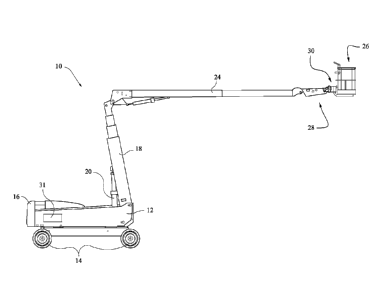
[0013] FIG. 1 shows an exemplary boom lift supporting an aerial work
platform;
[0014] FIG. 2 is a perspective view of a platform support assembly;
[0015] FIG. 3 is a side view of the load sensing system;
[0016] FIG. 4 is a sectional view through a center of the load sensing
system;
[0017] FIG. 5 is a close-up view of the load member in the exemplary
form of a carriage bolt and load cell; and
[0018] FIG. 6 is a flow chart showing an operational process of the
control system.
DETAILED DESCRIPTION
[0019] In the following description, the design will be described in the
context of an exemplary application to an aerial work platform (AWP) vehicle.
It is noted that the design is applicable to non-wheeled AWPs as well as other
boom concepts that do not include a "tower" boom, and the invention is not
meant to be limited to the exemplary application described.
[0020] FIG. 1 shows an exemplary aerial work platform vehicle 10
including a vehicle base 12 supported on wheels 14 and including a
counterweight 16. A tower boom 18 is pivotally connected to the vehicle base
4
CA 03018261 2018-09-18
WO 2017/177219
PCT/US2017/026761
12 and is pivoted by a lifting cylinder 20. An upper boom 24 is pivotally
connected to the tower boom 18, and a work platform 26 is connected via a jib
28 or the like to the upper boom 24. A platform load sensing system 30 is
connected between the upper boom 24 via a boom side framework ("boom
side") and the work platform 26 via a platform framework or weldment
("platform side"). A control system or controller 31 is shown schematically in
FIG. 1. The control system 31 communicated with the load sensing system 30
and controls operation of the vehicle 10.
[0021] FIGS. 2 and 3 show the platform load sensing system 30
connected between the boom 24 and the platform 26. The boom side 32
comprises a framework including a pin 34 to which the boom 24 or jib 28 may
be directly connected. The boom side 32 may be provided with a rotary
actuator that allows the operator to rotationally change a position of the
platform 26. The platform side 36 is comprised of a platform weldment 38 to
which the platform 26 may be secured. The boom side 32 is connected to the
platform side 36 by an upper bearing link 40 and a lower bearing link 42. The
upper and lower bearing links 40, 42 allow for relative motion between the two
sides 32, 36. The upper bearing link 40 is pinned to the boom side via pin 44
and to the platform side 32 via pin 46. Similarly, the lower bearing link 42
is
pinned to the boom side via pin 48 and pinned to the platform side via pin 50.
The pins 44, 46, 48, 50 are prevented from rotation using any suitable means,
for example by suitable lock pins 52 that extend through openings in outer
distal ends of the pins 44, 46, 48, 50.
[0022] A load member 54 such as a caniage bolt or the like is secured to
the platform side 36 via a first part 56 of a stop plate assembly that is
fixed to
the platform weldment 38. A second part 58 of the stop plate assembly is fixed
to the boom side 32. A load cell 60 is fixed to the boom side 32 below the
first
part 56 of the stop assembly. The load member 54 is positioned to engage the
load cell 60. In the exemplary embodiment shown in FIGS. 3-5, a hex bolt 62
CA 03018261 2018-09-18
WO 2017/177219
PCT/US2017/026761
or the like is secured in an opening in the load cell 60, and a head 64 of the
load
member 54 is engaged with the load cell 60 via the hex bolt 62. In some
embodiments, the head 64 of the load member 54 may directly engage the load
cell 60 without the use of the hex bolt 62 or the like, depending on the
construction of the load cell 60. An exemplary load cell is available from
Vishay Precision Group (VPG) of Rancho Cucamonga, California. In some
embodiments, the head 64 of the load member 54 and its engagement with the
load cell 60 (e.g., hex bolt 62) are controlled in both surface and mechanical
properties. For example, the load member (e.g., carriage bolt) head 64 may be
machined, coated or otherwise processed before installation in order to
provide
an appropriate friction reducing surface finish.
[0023] Because the upper and lower bearing links 40, 42 allow for
relative motion between the boom side 32 and the platform side 36, a load on
the platform 26 can be separated from its associated moment. That is, the load
moment is functionally eliminated by the upper and lower bearing links 40, 42.
With the load moment separated from the platform load, the load cell 60 is
thus
exposed only to the combined weight of the platform weldment 38, the
platform 26 and a load on the platform 26 in a perpendicular direction to the
working axis of load cell 60. This construction maximizes the accuracy of the
readings by minimizing the tangential components of the applied load at the
interface surface.
[0024] With continued reference to FIG. 5, a vertical gap 66 exists
between the first and second parts 56, 58 of the stop assembly. If the
platform
26 is lowered onto a surface or is otherwise subjected to an upward vertical
force, the platform side 36 will rise up relative to the boom side 32, thereby
unloading the load cell 60 until the gap 66 closes and further motion is
prohibited. The stop assembly including the first and second parts 56, 58
serves to limit the upward displacement of the platform side 36 to thereby
6
CA 03018261 2018-09-18
WO 2017/177219
PCT/US2017/026761
prevent the load cell electronics from losing calibration due to the upwards
force applied to the bottom of the platform 26.
[0025] The structural weldments, links, pins and bearings are engineered
to functionally eliminate deflections, which minimizes friction between the
link
pins and bearings, which thereby improves the overall accuracy of the system.
In some embodiments, low-friction, metal-polymer bearings are installed in the
links, along with composite thrust bearings between the links and their mating
weldments, which similarly serve to minimize friction and thereby improve the
overall accuracy of the system. The material selection of the bearings may
eliminate the need for periodically applying lubricant, thereby preserving the
long-term accuracy of the system.
[0026] In an exemplary construction, the load cell 60 may be a single
device with redundant internal strain gauges. The load cell 60 performs
diagnostics on each strain gauge independently and outputs error codes when
issues are detected. The load cell 60 transmits the strain gauge measurements,
diagnostic information and a serial number over a controller area network
(CAN) to the vehicle control system 31 using a predetermined protocol.
[0027] FIG. 6 is a flow chart showing operation of the control system 31
relative to the load sensing system 30. The control system 31 checks for
various errors based on output from the load cell 60. In step Si, the control
system checks for internal CAN or load cell errors, for example if the control
system does not receive messages from the load cell. The control system
receives load cell measurements and diagnostic information via CAN (S2) and
checks to ensure that the load cell is properly calibrated (S3). In some
embodiments, the load cell calibration is detected by comparing the load cell
serial number to what was stored by the control system during the last load
cell
calibration. If the load cell is not properly calibrated (no in S3), a
"platform
overloaded" status is output (S4). The control system checks for errors in
step
S5 and if so (yes in S5), the control system determines whether both strain
7
CA 03018261 2018-09-18
WO 2017/177219
PCT/US2017/026761
gauges are affected (S6). If both strain gauges are affected (yes in S6), a
"platform overloaded" status is reported (S7); if only one strain gauge is
affected (no in S6), the control system limits the machine to creep speed
(S8).
[0028] The control system checks whether a load cell underweight status
is detected (S9) when the platform load is significantly less than the
calibrated
weight or if the platform load remains negative while the machine is moving.
If so (yes in S9), a "platform overloaded" status is output (S7). A machine
capacity may be determined by the control system (S10) based on the machine
model and/or a platform capacity switch. A platform capacity switch may be
an operator controlled switch used to determine if the platform capacity is
restricted (higher load capacity) or unrestricted (reduced load capacity).
[0029] In step S11, the control system determines whether the load cell
is overloaded by comparing a load on the platform with the machine capacity.
The control system will output the "platform overloaded" status if the
platform
load is greater than the platform capacity for a predetermined amount of time.
The control system also determines whether the machine is moving (S12), and
if so (yes in S12), the control system determines whether a load cell stagnate
error is detected (S13), i.e., when the platform load remains unchanged while
the machine is moving. If the machine is not moving (no in S12) or the load
cell measurement stagnate is not detected (no in S13), the control system
outputs a "platform not overloaded" status (S14). The control system response
to an error thus depends on the error as noted above.
[0030] The load sensing system of the described embodiments includes
two sides that are pivotally connected and include a controlled load path from
the platform side to the boom side. Both sides are engineered structures that
support and transfer loads. The relative motion between the two sides and the
pair of controlled surfaces through which load is transferred from the
platform
side improves accuracy as compared with existing systems by separating the
platform load from its associated moment through the upper and lower bearing
8
CA 03018261 2018-09-18
WO 2017/177219
PCT/US2017/026761
links. Surfaces of the load path via the load member and the load cell are
controlled in both surface and mechanical properties to ensure that the shear
beam load cell is exposed only to the combined weight of the platform support,
platform and payload on the platform in a perpendicular direction to the
working axis of the load cell. This maximizes the accuracy of the readings by
minimizing tangential components of the applied load at the interface surface.
[0031] While the invention has been described in connection with what
is presently considered to be the most practical and preferred embodiments, it
is to be understood that the invention is not to be limited to the disclosed
embodiments, but on the contrary, is intended to cover various modifications
and equivalent arrangements included within the spirit and scope of the
appended claims.
9