Note: Descriptions are shown in the official language in which they were submitted.
CA 03018483 2018-09-20
PHOTOVOLTAIC MODULE INSTALLATION ROOF RENEWAL METHOD USING
PORTABLE ROLL FOAMING MACHINE, AND
ROOF RENEWAL STRUCTURE OBTAINED THEREBY
Field of the Invention
The present invention relates to a photovoltaic module
installation roof renewal method using a portable roll forming
machine and a roof renewal structure obtained thereby; and,
particularly, to a new photovoltaic module installation roof
renewal method using a portable roll forming machine that
avoids water leakage, has excellent structural safety, and
allows for simple construction and a reduced construction
period, and a roof renewal structure obtained thereby.
Background of the Invention
An old roof of a building is typically renewed when water
leaks or heat insulation deteriorates. Recently, however, a
roof may be renewed to install a photovoltaic module for
photovoltaic power generation.
In general, a roof panel is manufactured as a sandwich
panel type in which a heat insulator is interposed between two
metal panels, or manufactured as a single panel type by roll-
a single metal plate. Most roof panels have a fitting
projecting bar and an elastic clip at both ends thereof in a
width direction regardless of the type of roof panel, with the
-1-
CA 03018483 2018-09-20
elastic clip connected and fitted to a fitting projecting bar
of a neighboring panel in the width direction.
Due to factory space limitations or logistical
difficulties, a roof panel is cut to an arbitrary length and
then transported. Therefore, when a roof is being constructed,
a plurality of roof panels need to be connected in a
longitudinal direction to have a length corresponding to the
length of the roof. However, since there is no structure that
allows for the superimposition of neighboring panels at the
end portions in the longitudinal direction of the roof panel,
unlike at the end portions in the width direction, the roof
panels need to be connected in the longitudinal direction by
using additional connecting members. Using additional
connecting members makes the process inconvenient and time
consuming, and furthermore, allows for water leaks.
In addition, the presence of a plurality of connecting
portions of the roof panels on the roof reduces the structural
safety of the roof.
Summary of the Invention
In view of the above, the present invention provides a
photovoltaic module installation roof renewal method using a
portable roll forming machine that avoids concerns for water
leakage due to the non-existence of connecting portions in the
longitudinal direction of the roof panel and ensures excellent
structural safety, simple and stable construction and
-2-
installation of a photovoltaic module, and a reduced
construction period, and a roof renewal structure obtained
thereby.
In accordance with an aspect of the present invention,
there is provided a photovoltaic module installation roof
renewal method for installing a photovoltaic module by using a
portable roll forming machine on a roof of a building
constructed with a roof frame having a repetitively formed crest
and root, the method comprising the steps of: interposing a heat
insulator at the root of the roof frame; producing a
photovoltaic module installation roof panel in a length
corresponding to a length of the roof at a roof renewal site by
using the portable roll forming machine and transporting the
photovoltaic module installation roof panel onto the roof frame;
installing the photovoltaic module roof panel on the roof frame
at which the heat insulator is interposed; fastening a bracket
for installing a photovoltaic module on the photovoltaic module
installation roof panel; and installing the photovoltaic module
on the bracket, wherein the photovoltaic module installation
module roof panel includes a plurality of panel main bodies,
each of the panel main bodies having, at one end portion in a
width direction, a fitting projecting bar with a concave groove
extending on a top surface thereof along a longitudinal length
and, at the other end portion in the width direction, an elastic
clip, and wherein in the installing the photovoltaic module roof
panel on the roof frame at which the heat insulator is
-3-
CA 3018483 2020-01-23
*
interposed, the panel main bodies are connected to one another
by inserting the elastic clip of one of the panel main bodies
into the fitting projecting bar of its neighboring panel main
body.
In another aspect of the present invention, there is
provided a photovoltaic module installation roof renewal
structure comprising: a heat insulator interposed at a root of a
roof frame in which a crest and the root are repetitively formed
to constitute a roof of a building; and a photovoltaic module
installation roof panel installed on the roof frame at which the
heat insulator is interposed, wherein the photovoltaic module
installation roof panel has a length corresponding to a length
of the roof, and no connecting portion is formed in a
longitudinal direction of the photovoltaic module installation
roof panel, wherein the photovoltaic module installation module
roof panel includes a plurality of panel main bodies, each of
the panel main bodies having, at one end portion in a width
direction, a fitting projecting bar with a concave groove
extending on a top surface thereof along a longitudinal length
and, at the other end portion in the width direction, an elastic
clip, and wherein, when the photovoltaic module roof panel is
installed on the roof frame, the panel main bodies are connected
to one another by inserting the elastic clip of one of the panel
main bodies into the fitting projecting bar of its neighboring
panel main body.
-3a-
CA 3018483 2020-01-23
Effects of the Invention
In the present invention having the above-described
configuration, a photovoltaic module installation roof panel 100
is manufactured to have a length corresponding to the length of
a roof at a roof renewal site and be used for roof renewal.
Therefore, there is no connecting portion in the
-3b-
CA 3018483 2020-01-23
CA 03018483 2018-09-20
longitudinal direction of the photovoltaic module installation
roof panel 100 and accordingly, the conventional problem of
water leakage at the connecting portion in the longitudinal
direction of the roof panel is resolved and the structural
safety of the roof is improved.
Further, in the present invention, the roof is renewed
without being removed and, thus, the renewal operation is
simplified and the construction period can be shortened. Also,
since it is required to interpose the heat insulator 4 on the
roof and connect the roof panel 100 only in the width
direction without being connected in the longitudinal
direction, the construction of the roof panel 100 is
simplified and the construction period can be shortened.
Moreover, due to the presence of a bracket fitting groove
124 for fitting a photovoltaic module installation bracket 40
to the photovoltaic module installation roof panel 100, a
photovoltaic module can be easily constructed.
Therefore, in accordance with the present invention, it
is possible to provide, by utilizing the old roof, a roof
capable of photovoltaic generation with no concern for water
leakage and excellent heat insulating properties at a low cost.
Brief Description of the Drawings
Fig. 1 is an exploded perspective view of a photovoltaic
module installation roof panel used in an embodiment of the
present invention.
-4-
CA 03018483 2018-09-20
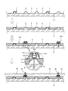
Fia. 2 shows the construction process of the above
embodiment.
Fig. 3 shows the production and lifting of the roof panel.
Detailed Description of the Embodiments
Hereinafter, embodiments of the present invention will be
described with reference to the accompanying drawings.
The present invention relates to a method of renewing a
roof of a building constructed with metal roof panels in which
crests and roots are extended along a longitudinal direction
to a roof with photovoltaic module installation roof panels.
The photovoltaic module installation roof panel 100 used
in the present invention is manufactured by roll-forming a
metal plate. For example, as shown in Fig. 1, the photovoltaic
module installation roof panel 100 includes a panel body 110
and a fitting rail 130. A fitting projecting bar 112 is
provided at one end portion in the width direction of the
panel body 110 and an elastic clip 122 is provided at the
other end portion in the width direction of the panel body 110.
The fitting rail 130 is inserted into the fitting projecting
bar 112.
The following is a detailed description of the
photovoltaic module installation roof panel 100. A concave
groove 114 is extended along the longitudinal direction on the
top surface of the fitting projecting bar 112. The fitting
rail 130 is inserted into the concave groove 114 of the
-5-
CA 03018483 2018-09-20
fitting projecting bar 112.
Inwardly directed hooks 132 are
formed at upper ends of both sidewalls in the width direction
of the fitting rail 130.
Referring to Fig. 2, the elastic clip 122 has a shape
that allows the fitting projecting bar 112 to be accommodated
therein. The elastic clip 122 of one roof panel 100 is
elastically fitted to a fitting projecting bar 112 of a
neighboring roof panel 100. A bracket fitting groove 124 to be
inserted into the fitting rail 130 is formed on the top
surface of the elastic clip 122. A bracket 40 for installing
the photovoltaic module 30 is fitted to the bracket fitting
groove 124.
As will be described later, the roof panel 100 is fixed
to the roof by fastening a bolt 6 to the fitting rail 130, and
the elastic clip 122 of the roof panel 100 is elastically
fitted to the fitting projecting bar 112. In this manner, a
plurality of roof panels 100 are connected and assembled in
the width direction. The bracket fitting groove 124 is
inserted into the fitting rail 130 by fitting the elastic clip
122 to the fitting projecting bar 112. The bracket fitting
groove 124 is prevented from being separated from the fitting
rail 130 by the hooks 132 formed at the upper ends of the
fitting rail 130. Accordingly, the fitting force between the
elastic clip 122 and the fitting projecting bar 112 is
improved.
The photovoltaic module installation roof panel 100 has a
length corresponding to the length of the roof to be renewed.
-6-
CA 03018483 2018-09-20
In other words, in the case of a gable roof, the roof panel
100 has a length corresponding to the length from the ridge to
an eave of the roof. In the case of a flat roof or a roof
inclined on one side, the roof panel 100 has a length
corresponding to the length of the roof in order to prevent
water leakage and improve the structural stability without
providing connecting portions in the longitudinal direction of
the roof panel 100 at the time of the roof renewal, as will be
described later.
For a photovoltaic module installation roof panel 100 to
have the above-described length, the panel is required to be
manufactured at a considerable length. However, as described
above, it is substantially difficult to manufacture and supply
the photovoltaic module installation roof panel 100 having the
required length due to manufacturing factory space limitations,
logistical problems, and the like.
Therefore, in the present invention, the photovoltaic
modulation installation roof panel 100 is directly
manufactured and used at the roof renewal site. In other words,
the roof panel 100 is manufactured at the site where the roof
is renewed by using a portable roll forming machine 10, i.e.,
in an open space. For example, as shown in Fig. 3, a lifting
device 20 is provided in front of the portable roll forming
device 10 so that the roof panel 100 that is roll-formed by
the portable roll forming machine 10 can be directly lifted
onto the roof of the building.
Since the photovoltaic module installation roof panel 100
-7-
CA 03018483 2018-09-20
is manufactured in the open space and lifted up to the roof,
the roof panel 100 can be produced to have a length
corresponding to the length of the roof.
A loading carrier loaded with the portable roll forming
machine 10 is connected to a vehicle. Preferably, as
illustrated in the drawing, the upper part of the loading
carrier can be opened and closed and the roll forming machine
projects from and retracts into the upper part of the open
loading carrier. Since the portable roll forming machine 10
has a known configuration, detailed description thereof will
be omitted.
Both the panel body 110 and the fitting rail 130 may be
manufactured by the portable roll forming machine 10. However,
it is also possible to assemble the pre-manufactured fitting
rail 130 to the panel body 110 by using the portable roll
forming machine 10. In some cases, it is possible to
manufacture only the panel body 110 by using the portable roll
forming machine 10, lift the panel body 110 onto the roof, and
fit the fitting rail 130 to the panel body 110 on the roof. In
addition, the photovoltaic module installation roof panel 100
can be manufactured by inserting a plurality of fitting rails
130 having a predetermined length into the concave grooves 114
of the fitting projecting bar 112.
The following is a detailed description of the process of
renewing the roof of the building by using the photovoltaic
module installation roof panel 100 configured as described
above.
-8-
CA 03018483 2018-09-20
1) First, the roof of the building to be renewed is
cleaned and unnecessary structures installed on the roof are
removed.
2) Roots 3 of the roof frame 1 constituting the roof are
filled with a heat insulator 4. A known material such as
urethane foam or the like is used as the heat insulator 4.
3) The photovoltaic module installation roof panel 100 is
manufactured and lifted onto the roof by using the portable
roll forming machine 10.
As described above, the photovoltaic module installation
roof panel 100 is directly manufactured and lifted onto the
roof at the roof renewal site by using the portable roll
forming machine 10. The photovoltaic module installation roof
panel 100 is manufactured to have a length corresponding to
the length of the roof to be renewed.
Therefore, the photovoltaic module installation roof
panel 100 is connected only in the width direction without
being connected in the longitudinal direction. As described
above, the roof panel 100 is lifted up to the roof filled with
the heat insulator 4. Then, the photovoltaic module
installation roof panel 100 is fixed to the roof frame 1
filled with the heat insulator 4 by fastening the bolt 6 to
the fitting rail 130 inserted into the concave groove 114 of
the roof panel 100. The bolt 6 penetrates through the roof
panel 100 and the roof frame 1, and is inserted into and fixed
to a support frame 9 of the roof.
In this manner, the photovoltaic module installation roof
-9-
CA 03018483 2018-09-20
panel 100 is fixed to the roof (e.g., the roof frame and the
support frame of the roof). Then, an elastic clip 122 of a
neighboring roof panel 100 is inserted into the fitting
projecting bar 112 of the pre-installed roof panel 100. By
connecting the photovoltaic module installation roof panels
100 in the width direction, the roof panels 100 are
constructed to completely cover the roof.
5) Next, the photovoltaic module 30 is installed on the
photovoltaic module installation roof panel 100 installed on
the roof.
A bracket 40 for installing the photovoltaic module 30 is
fitted to the bracket fitting groove 124 of the roof panel 100,
and the photovoltaic module 30 is installed by using the
bracket 40. For example, as shown in Fig. 2, the position of
the photovoltaic module 30 can be fixed by installing a part
of the bracket 40 to be aligned with the bracket fitting
groove 124. Since an inlet portion of the bracket fitting
groove 124 is narrower than an internal space thereof, if the
bracket 40 can be partially aligned with the bracket fitting
groove 124, it is only required to fit the bracket 40 to the
bracket fitting groove 124 without any additional process of
fixing the bracket 40 to the roof panel 100. For example, when
the bracket fitting groove 124 has a T-shaped or a triangular
cross section, the bracket 40 can have a neck and a head
(greater in diameter than the neck). The head is supported on
one surface of the photovoltaic module 30. The neck penetrates
through the photovoltaic module 30. The end of the neck can be
-10-
CA 03018483 2018-09-20
fitted to the bracket fitting groove 18, so to be accommodated
in the internal space of the bracket fitting groove 124.
As described above, in the present invention, the roof is
renewed into a roof on which a photovoltaic module can be
installed without being removed. Therefore, the cost is
reduced and the construction period is also shortened.
In particular, since the photovoltaic module installation
roof panel 100 is directly manufactured and used at the roof
renewal site, the photovoltaic module installation roof panel
100 can have the desired length without having to connect
separate roof panels in the longitudinal direction.
Accordingly, there is no connecting portion in the
longitudinal direction of the photovoltaic module installation
roof panel 100, which makes it possible to avoid concerns for
water leakage and ensure a safer structure.
In addition, since there is no need to connect the roof
panels in the longitudinal direction, the construction is
simple, the construction efficiency is improved, and the
construction period is shortened.
While the embodiments of the present invention have been
described, the present invention is not limited to the above-
described embodiments, and various modifications can be made
within the scope of the technical idea of the present
invention. Although the present invention has been described
and illustrated in connection with the embodiments, it will be
understood by those skilled in the art that various changes
and modifications can be made without departing from the scope
-11-
CA 03018483 2018-09-20
of the invention as defined in the following claims.
-12-