Note: Descriptions are shown in the official language in which they were submitted.
CA 03018543 2018-09-20
WO 2017/165604
PCT/US2017/023740
NOISE REDUCTION ASSEMBLY FOR AUSCULTATION OF A BODY
CLAIM OF PRIORITY
This application is a continuation-in-part of a currently
pending U.S. patent application having Serial No. 14/607,513
and a filing date of January 28, 2015, which is a
continuation-in-part of pending U.S. patent application having
Serial No. 14/476,134 and a filing date of September 3, 2014,
which made a claim of priority to a U.S. Provisional patent
application having Serial No. 61/980,302, filed April 16,
2014.
This application further claims priority to provisional
patent application 62/313,236, filed March 25, 2016.
Each of the above prior-filed applications are hereby
incorporated by reference in their entireties.
BACKGROUND OF THE INVENTION
Field of the Invention
The present invention relates to a device for
auscultation of a body. An embodiment of the device includes a
housing dimensioned and configured for disposition in an
operative orientation relative to a predetermined portion of
the body, the housing having a plurality of chambers disposed
therewithin, the housing also being surrounded by a concentric
structure. A further embodiment also comprises one or more
noise impeding materials disposed within the chamber(s) for
reducing ambient noise leakage into the auscultation device of
the present invention.
DESCRIPTION OF THE RELATED ART
Auscultation, or the term for listening to the internal
sounds of a body, is of great importance to many disciplines,
such as the medical fields. For example, auscultation of a
body, such as the body of a patient, assists a medical
1
CA 03018543 2018-09-20
WO 2017/165604
PCT/US2017/023740
professional in the diagnosis of ailments that may affect the
patient. Such may be traditionally achieved with a
stethoscope, which may use a wide bell and/or a diaphragm to
listen to a narrow range of low frequency acoustic signals,
such as those associated with patient's heartbeat. However,
such approaches are fundamentally inadequate for many other
diagnostic purposes, such as receiving acoustic signals
associated with higher frequency signals.
Accordingly, what is needed in the art is a device
structured to receive acoustic signals in a wider band of
frequencies, including but not limited to high-frequency
sounds. Such acoustic signals include frequencies associated
with other functions of the body useful in diagnosis, such as
swallowing, breathing, and blood flow, and are outside the
capabilities of traditional stethoscope devices.
Further, what is needed in the art is a system
incorporating such a device. Such a system may incorporate the
device to facilitate in the diagnosis of patients and/or other
medical procedures carried out by medical professionals. Such
a system would utilize the acoustic signals received by the
device, and process the signals to assist in detection of, for
example, disorders of the gut, the joints, the lungs, blood
flow, or swallowing.
SUMMARY OF THE INVENTION
The present invention relates to a device for
auscultation of a body, such as the body of a patient. An
illustrative embodiment of a device in accordance with the
present invention comprises a housing dimensioned and
configured for disposition in an operative orientation
relative to a predetermined portion of the body. Examples of
such predetermined portion of the body include but are not
limited to the throat and area corresponding to the lungs.
Included within the housing are a plurality of chambers
collectively structured to receive an acoustic signal at least
2
CA 03018543 2018-09-20
WO 2017/165604
PCT/US2017/023740
when the housing is disposed in the operative orientation. The
acoustic signals are produced by the body and may correlate
with various bodily processes, conditions, etc. Receiving such
signals may facilitate in diagnostics and other medical
procedures. Accordingly, the plurality of chambers are
cooperatively structured and/or shaped such that acoustic
signals produced by the body enter the device for detection.
Additionally, at least partially disposed within one of
the plurality of chambers is at least one transducer. The
transducer is structured to convert the audio signal received
by the device into an electrical signal. By way of example
only, the transducer may comprise a microphone. The electrical
signal may then be transmitted to other elements of a
diagnostic system, as will be further described herein.
A preferred embodiment of the present invention further
comprises proximal and distal ends, the proximal end being
structured to define an opening. The opening is dimensioned
and configured for engagement with the predetermined portion
of the body.
Further, the plurality of chambers comprises an acoustic
capture chamber in a sound receiving relationship relative to
the opening. Accordingly, the sound receiving relationship
permits the passage of the acoustic signal from the opening to
at least the acoustic capture chamber. In the preferred
embodiment, this is achieved by way of the opening permitting
entry of the acoustic signal into the acoustic capture
chamber.
It should be appreciated that the shape of the acoustic
capture chamber may vary among the various embodiments of the
present invention. However, in a preferred embodiment, the
diameter of the distal end of the acoustic capture chamber is
less than or equal to the diameter of a proximal end. An
example of a geometric shape having such a configuration
wherein one end comprises a smaller diameter than an opposing
end is a frustum of a right circular cone. Accordingly,
3
CA 03018543 20113-0
WO 2017/165604
PCT/US2017/023740
various embodiments of an acoustic capture chamber may
comprise such a configuration. However, the acoustic chamber
may comprise any suitable shape in accordance with the present
invention, including but not limited to the foregoing.
In addition, the plurality of chambers comprises a
primary resonance chamber disposed in sound receiving relation
relative to the acoustic capture chamber. In a preferred
embodiment, the transducer is at least partially disposed
within the primary resonance chamber. In addition, in a
preferred embodiment, the transducer is movably disposed in
the primary resonance chamber.
Moreover, a preferred embodiment of the primary resonance
chamber comprises a resonance adjustment member movably
disposed within the primary resonance chamber. Adjustment of
the resonance adjustment member, such as by moving it within
the primary resonance chamber, facilitates alteration of
acoustic properties of the device. Further, in a preferred
embodiment such adjustment may be carried out during use of
the device.
A preferred embodiment further comprises a secondary
resonance chamber disposed in a sound receiving relationship
relative to the acoustic capture chamber. The secondary
resonance chamber facilitates "tuning" of the device, such as
by adjusting a range of acoustic signals that the device
receives or to which it is most sensitive. In a preferred
embodiment, this is accomplished by altering the physical
parameters, such as the volume, of the secondary resonance
chamber. Further, in a preferred embodiment, at least one
transducer is movably disposed at least partially within the
secondary resonance chamber. Accordingly, moving of the
transducer facilitates "tuning" of the device, such as by
altering the resonant properties of the device.
The present invention further relates to a signal
processing system. In a preferred embodiment of the system, at
least one device is in communication with a plurality of
4
CA 03018543 2018-09-20
WO 2017/165604
PCT/US2017/023740
components collectively configured to process an electrical
signal received from the device. The electrical signal
corresponds to the acoustic signal received by the device from
the body. The plurality of components in the preferred
embodiment includes an amplification component, a digital
signal processing component, an analysis component, a pattern
recognition component, and at least one output component.
Another preferred embodiment of the present invention
relates to a device for auscultation of a body to include low
frequency signals, including those at or below 500 Hz.
Accordingly, the device in this embodiment may comprise a
housing as well as a concentric structure.
The housing may comprise a plurality of chambers
collectively structured to receive an acoustic signal at least
when the housing is disposed in the operative orientation,
such as when the proximal end of the housing is placed up
against a resonating body such as a patient's body for
auscultation. The
plurality of chambers may comprise an
acoustic capture chamber and a primary resonance chamber, and
may further comprise a secondary resonance chamber in some
embodiments. A transducer may be disposed at least partially
in the primary resonance chamber and/or the secondary
resonance chamber. The acoustic capture chamber is disposed
in a sound receiving relationship relative to an opening of
the housing, and is structured to receive acoustic signals of
higher frequencies, such as those at or above 500 Hz.
The concentric structure is formed circumferentially in
surrounding relations to the proximal end of the housing. The
proximal end of the concentric structure may be flush or
parallel with the proximal end of the housing. An exterior of
the concentric structure may form a bell shape, such that an
opening of the concentric structure along its proximal end
extends to a substantially hollow opening therein, while the
distal portion may form a substantially flat profile in
surrounding and abutting relations with an exterior of the
5
CA 03018543 2018-09-20
WO 2017/165604
PCT/US2017/023740
housing.
The housing may further comprise a low frequency
receiver, such as a bore formed between an exterior of the
housing but within the canopy of the concentric structure that
reaches inward to an interior opening of the acoustic capture
chamber. This low frequency receiver or bore is structured to
receive the lower frequency sounds at the acoustic capture
chamber and/or at the primary or secondary resonance
chamber(s) housing the transducer. The
transducer may then
convert both the received higher frequency signals from the
opening of the housing, as well as the low frequency signals
from the opening of the concentric structure, into an
electrical input signal for further processing.
A further embodiment of the present invention comprises
layering an interior dampening layer in surrounding and
overlying relations relative to an auscultation device on all
exterior surfaces except the proximal end placed against the
body. A
further exterior dampening layer may is further
disposed in surrounding and overlying relations relative to
the interior dampening layer. Each of the interior dampening
layer, exterior dampening layer, and the auscultation device
itself or the exterior surface thereof, may be formed of a
different material to maximizing the range of extraneous and
external noises that is impeded.
These and other objects, features and advantages of the
present invention will become clearer when the drawings as
well as the detailed description are taken into consideration.
BRIEF DESCRIPTION OF THE DRAWINGS
For a fuller understanding of the nature of the present
invention, reference should be had to the following detailed
description taken in connection with the accompanying drawings
in which:
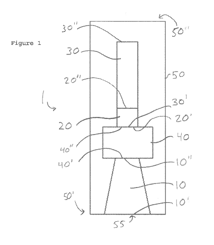
Figure 1 is a schematic representation of a side view of
an illustrative embodiment of a device in accordance with the
6
CA 03018543 20113-0
WO 2017/165604
PCT/US2017/023740
present invention.
Figure 2 is a schematic representation of a bottom view
of the embodiment of Figure 1.
Figure 3 is a schematic representation of an illustrative
embodiment of a system in accordance with the present
invention.
Figure 4 is a schematic representation of a side view of
an illustrative embodiment of a device in accordance with the
present invention.
Figure 5 is a schematic representation of a side view of
an illustrative embodiment of a device in accordance with the
present invention.
Figure 6 is a schematic representation of a side view of
the embodiment of Figure 5.
Figure 7 is a schematic representation of a side view of
an illustrative embodiment of a device in accordance with the
present invention.
Figure 8 is a schematic representation of another device
in accordance with the present invention capable of receiving
both higher and low frequencies sound signals.
Figure 9 is a schematic representation of an illustrative
embodiment of a device in accordance with the present
invention.
Figure 10 is a schematic representation of a bottom view
of the embodiment of Figure 8.
Figure 11 is a schematic representation of a side cutaway
view of a noise reduction assembly of the present invention.
Figure 12 is a schematic representation of a bottom view
of a noise reduction assembly of the present invention.
Like reference numerals refer to like parts throughout
the several views of the drawings.
DETAILED DESCRIPTION OF THE PREFERRED EMBODIMENT
As illustrated in the accompanying drawings, the present
invention is directed to a device and system for auscultation
7
CA 03018543 2018-09-20
WO 2017/165604
PCT/US2017/023740
of a body. As described above, auscultation relates to the
practice of capturing acoustic signals produced by the body,
such as but not limited to for purposes of medical diagnosis.
Accordingly, it should be appreciated that the body may be a
human body, i.e. a patient, but may also be any other suitable
source of acoustic signals.
In accordance with the illustrative embodiment as shown
in Figure 1, a device 1 comprises a housing 50. The housing 50
is dimensioned and configured for disposition in an operative
orientation relative to a predetermined portion of the body.
For example, the housing 50 may be placed relative to and/or
against a portion of the body that corresponds to a patient's
throat, such as for purposes of monitoring acoustic signals
associated with a patient's breathing and/or swallowing.
Accordingly, the housing 50 comprises a plurality of
chambers 10, 30, 40 disposed within the housing. The chambers
are collectively structured to receive an acoustic signal
produced by the body. In a preferred embodiment, the chambers
10, 30, 40 are collectively structured such that receiving the
acoustic signal causes the housing 50 to resonate. Further, in
a preferred embodiment, chambers 10, 30, 40 are collectively
structured such that housing 50 resonates at a frequency
and/or frequencies within the range of about 20 Hertz to about
2,000 Hertz. In addition, the housing 50 in a preferred
embodiment comprises a material of construction chosen for
particular resonant properties.
With further reference to Figure 1, the housing 50
comprises a proximal end 50' and a distal end 50". The
proximal end 50' is structured for disposition in an operative
orientation relative to a predetermined portion of the body,
such as an area of the neck, throat, an area of the chest,
and/or any other desired or suitable area. Such disposition of
the proximal end 50' comprises engagement of the housing 50
with the body such that the housing 50 and the body define a
confronting engagement with one another.
8
CA 03018543 20113-0
WO 2017/165604
PCT/US2017/023740
Further, the proximal end 50' is structured to include an
opening 55. The opening 55 is dimensioned and configured for
engagement with the predetermined portion of the body when the
housing 50 is in the operative orientation. Engagement of the
opening 55 with the body includes disposition of the opening
55 in close proximity to the body such that acoustic signals
produced by the body pass through the opening 55 and into the
housing 50. Accordingly, various embodiments of the present
invention may comprise varying configurations and/or
dimensions of openings 55 suitable for engagement with varying
predetermined portions of the body, as may be determined by
e.g. the size and location of the predetermined portion of the
body.
The plurality of chambers 10, 30, 40 of the embodiment of
Figure 1 comprises an acoustic capture chamber 10. The
acoustic capture chamber 10 is disposed in a sound receiving
relationship relative to the opening 55. Accordingly, the
opening 55 facilitates passage of acoustic signals into the
acoustic capture chamber 10.
Figure 2 shows the embodiment of Figure 1 as seen from a
view toward the opening 55. The acoustic capture chamber
comprises a proximal end 10' and a distal end 10". Further,
various embodiments of an acoustic capture chamber 10
comprising various configurations are contemplated. As is
evident from Figure 2, in a preferred embodiment, the distal
end 10" of the acoustic capture chamber 10 comprises a
diameter less than a diameter of the proximal end 10'. Figure
4 illustrates a preferred embodiment wherein the distal end
10" of the acoustic capture chamber 10 comprises a diameter
equal to a diameter of the proximal end 10'.
With further reference to Figure 1, a preferred
embodiment of the device 1 comprises a primary resonance
chamber 30. The primary resonance chamber 30 is disposed in a
sound receiving relationship relative to the acoustic capture
chamber 10. Accordingly, acoustic signals produced by the body
9
CA 03018543 20113-0
WO 2017/165604
PCT/US2017/023740
that are captured and/or received by the acoustic capture
chamber 10 and are received by the primary resonance chamber
30.
Further, adjustment of the resonant properties of the
housing 50 may be accomplished. This may even be accomplished
during use of the device 1. For example, varying of internal
dimension of the chambers 10, 30, 40 facilitates the altering
in at least one embodiment of the frequency and/or frequencies
at which the housing 50 resonates. Further, as shown in the
preferred embodiment of Figures 5 and 6, a resonance
adjustment member 60 is movably disposed at least partially
within the primary resonance chamber 30. Figures 5 and 6
demonstrate two possible positions of the resonance adjustment
member 60 within the primary resonance chamber 30, but should
not be taken as being the only contemplated or otherwise
construed as limiting. Accordingly, moving, such as by
sliding, telescoping, and/or any other suitable method, of the
resonance adjustment member 60 within the primary resonance
chamber 30 facilitates the alteration of resonant properties
of the housing 50, and accordingly may facilitate a change in
the acoustic signals which the device receives or to which the
device is most tuned.
The embodiment of Figure 1 further comprises a secondary
resonance chamber 40 disposed in a sound receiving
relationship relative to the acoustic capture chamber 10. The
secondary resonance chamber facilitates "tuning" of the device
1, which should be understood as the adjusting of the range of
acoustic signals that the device 1 receives or to which it is
most sensitive. This may be accomplished by, for example,
varying the dimensions of the secondary resonance chamber 40.
Further, a proximal end 40' of the secondary resonance chamber
is in communication with the distal end 10" of the acoustic
capture chamber 10. Additionally, a distal end 40" of the
secondary resonance chamber is in communication with the
35 proximal end 30' of the primary resonance chamber 30.
CA 03018543 2018-09-20
WO 2017/165604
PCT/US2017/023740
In various embodiments of the device 1, the acoustic
capture chamber 10 and the secondary resonance chamber 40 are
in fluid communication. Accordingly, the distal end 10" of the
acoustic capture chamber and the proximal end 40' of the
secondary resonance chamber are correspondingly structured
such that fluid, e.g. air, passes between the two chambers 10,
40. This may further facilitate communication of acoustic
signals between the chambers 10, 40.
A preferred embodiment of a device 1, such as that of
Figure 1, further comprises at least one transducer 20 or, as
shown in Figure 7, a plurality of transducers 20, 22. An
example of a transducer 20, 22 includes but is not limited to
a microphone. The transducer 20, 22, such as shown in Figure
1, is structured to convert the acoustic signal into at least
one electrical signal. The electrical signal may then be
processed, such as to facilitate diagnosis.
In addition, and with further reference to Figure 1, the
transducer 20 is disposed at least partially within the
primary resonance chamber 30. However, the transducer 20 is
not limited to disposition within the primary resonance
chamber. Accordingly, it is contemplated that various other
embodiments in accordance with the present invention comprise
a transducer disposed at least partially in a corresponding
one of the chambers 10, 30, 40.
Further, still other embodiments comprise a plurality of
transducers, each of which is at least partially disposed in
corresponding ones of the plurality of chambers 10, 30, 40.
For example, and with reference to Figure 7, at least one
transducer, but preferably a plurality of transducers 20, 22
are disposed within the housing 50. Specifically, a first
transducer 20 is preferably disposed at least partially within
the primary resonance chamber 30, and a second transducer 22
is preferably disposed at least partially within the secondary
resonance chamber 40. Further, the transducers 20, 22 may be
movably disposed at least partially within their respective
11
CA 03018543 2018-09-20
WO 2017/165604
PCT/US2017/023740
chamber. Accordingly, the transducers are independently and/or
collectively moveable within their respective chamber or
chambers. This facilitates alteration of the resonant
properties of the housing 50 and/or alter frequencies of
acoustic signals received by the transducers 20, 22 for
conversion into at least one electrical signal.
Turning now to Figure 3, an embodiment of a system 2 in
accordance with the present invention is provided. The system
2 comprises a device 1 for auscultation of a body. It should
be appreciated that the device 1 may be the embodiment of
Figure 1, but may also be any embodiment of a device 1
consistent with the present invention. In a preferred
embodiment of a system 2 as illustrated in Figure 3, the
device 1 is in communication with a plurality of components
100, 200, 300, 400, 500, 510. The components include, but are
not limited to, a processing component 200, an analysis
component 300, a pattern recognition component 400, and at
least one output component 500, 510. The output components may
comprise a display component 500 and an audio output component
510. Further, the system 2 may be configured to process the
electronic signal using Dynamic Range Control and
Equalization.
The amplification component 100 is structured to amplify
an electronic signal received from the device 1. An example of
an amplification component is a microphone preamplifier.
The processing component 200 is structured to process the
amplified signal received from the amplification component
200. The processing component 200 comprises a digital signal
processor. Further, the processing component 200 is structured
to process the amplified signal to facilitate further
analysis. Additionally, the processing component 200 may be
structured to incorporate pre-post AGC filtering, audio
frequency dynamic range control and/or equalization. In a
preferred embodiment, an audio output component 510 is in
communication with the processing component 200. Accordingly,
12
CA 03018543 2018-09-20
WO 2017/165604
PCT/US2017/023740
the audio output component 510 is structured to facilitate
listening to the processed signal, such as by a medical
professional. An example of an audio output component 510
includes headphones.
The analysis component 300 receives the processed signal
from the processing component 200. The analysis component 300
is structured to produce an analyzed signal. Accordingly, the
analysis component 300 may perform e.g. a Fast Fourier
Transform analysis to produce the analyzed signal.
The analyzed signal is then transmitted to a pattern
recognition component 400 structured to recognize patterns in
the analyzed signal, such as those pertaining to any
combination of the frequency, intensity or time domain.
Further, the pattern recognition component 400 may be
configured to match detected patterns in the analyzed signal
with potential diagnosis and/or medical conditions.
Accordingly, the pattern recognition component 400 is
configured to output the potential diagnosis and/or medical
condition in accordance with the corresponding detected
pattern or patterns. The analyzed signal is further
transmitted to a display component 500. Examples of a display
component 500 include visual display devices structured for
the output of a spectrogram. The display component 500 in
various embodiments may further be configured to highlight
issues detected by the system 2 and/or that may facilitate or
otherwise aid in the diagnosis process.
While the above device embodiment is effective for
frequencies above 500 Hz, in other additional embodiments it
may also be desirable to capture lower frequency sounds, i.e.
at or below 500 Hz. As
such, the present invention further
contemplates a device for auscultation of a body that may
auscultate a wider range of frequencies, including those above
and below 500 Hz simultaneously, as illustrated in Figures 8-
10.
Drawing attention to Figure 8, a device 800 for
auscultation of a body may comprise a housing 50 and
13
CA 03018543 2018-09-20
WO 2017/165604
PCT/US2017/023740
concentric structure 800.
The housing 50 may comprise at least one of the
embodiments for a device for auscultation as recited above, in
accordance to Figures 1-7. As such, housing 50 may comprise a
proximal end 50' and a distal end 50". The proximal end 50'
of the housing 50 includes an opening 55 dimensioned and
configured for engagement with a predetermined portion of a
body when the housing 50 is disposed in an operative
orientation relative to the body. The
body may comprise a
human or mammalian body which resonates internal sounds for
auscultation, and the operative orientation may include
placing the proximal end 50' of the housing in direct abutting
relations to a portion of the body.
The housing 50 may further comprise a plurality of
chambers disposed therewithin, which are collectively
structured to receive an acoustic signal at least when the
housing 50 is disposed in the operative orientation. At least
one transducer 20 is at least partially disposed in a
corresponding one of the chambers and structured to convert
the received acoustic signal from the opening 55 of the
housing 50 into an electrical signal.
The plurality of chambers may comprise an acoustic
capture chamber 10 and a primary resonance chamber 30. A
further secondary resonance chamber 40 may also be included,
such as illustrated in the above embodiments of Figures 1-7.
The transducer 20 is preferably disposed in the primary
resonance chamber 30, which may also comprise a notch 90 for
inserting a communications cable, such as 95, therethrough.
However, the transducer 20 may also be disposed in another
chamber, such as the secondary resonance chamber 40.
Transducer 20 may comprise a microphone or any other
combination of circuits or devices capable and appropriate for
capturing converting acoustic sound waves into electrical
input signals. The acoustic capture chamber 10 may comprise a
conical profile, such that the distal end of the chamber
14
CA 03018543 2018-09-20
WO 2017/165604
PCT/US2017/023740
comprises a diameter less than the diameter of the proximal
end. The acoustic capture chamber 10 is disposed in a sound
receiving relationship relative to the opening 55 of the
housing 50. For
instance, the opening 55 of the housing 50
may open into the acoustic capture chamber 55, as illustrated
in Figure 8. The
shape, dimension, profile, and other
configurations of the acoustic capture chamber is configured
and intended to receive acoustic signals of at or above the
500 Hz frequency.
The concentric structure 800 is formed circumferentially
in surrounding relations to the proximal end 50' of the
housing 50, for capturing low frequency signals, such as those
at or below 500 Hz. The concentric structure 800 may comprise
a proximal end 801 and a distal end 802, the proximal end 801
includes the opening 855 dimensioned and configured for
engagement with a predetermined portion of the body. The
opening 855 of the concentric structure 800 is structured to
receive the lower frequency signals of a resonating body. In
at least one embodiment, the proximal end 801 of the
concentric structure 800 may be parallel to the proximal end
50' of the housing 50. The distal end 802 of the concentric
structure 800 may be formed circumferentially in abutting
relations to an exterior of the housing 50. An exterior 803
of the concentric structure 801 may form a partial semi-dome,
bell shape, or convex shape, while the distal portion 802 may
be form a substantially flat profile.
In order to receive the low frequency signals from the
concentric structure 800 at the transducer 20, the housing 50
comprises a low frequency receiver 810 in sound communication
relations between the acoustic capture chamber 55 and the
concentric structure 800. In
the embodiment shown, the low
frequency receiver 810 may comprise a bore 810, in accordance
to Figures 8 and 10, formed from an interior opening of the
concentric structure 800 to an interior of the acoustic
capture chamber 55 in order to receive acoustic waves from the
CA 03018543 2018-09-20
WO 2017/165604
PCT/US2017/023740
opening 855 of the concentric structure 800. In
some
embodiments, the low frequency receiver 810 may be structured
to feed the signal directly into the primary resonance chamber
30 and/or the secondary resonance chamber 40 housing the
transducer 20. The
transducer 20 receives both the higher
frequency signals from the opening 55 of the acoustic capture
chamber 10, as well as the low frequency signals from the
opening 855 of the concentric structure 800, through the low
frequency receiver 810.
Both the higher frequency signals and the low frequency
signals may then be either simultaneously or selectively
converted into electrical input signals by the transducer,
which may then be further processed for signal clarity or for
desired audio effects as described above. The
signal may
travel up a communications cable 95 shown in Figure 9 for this
processing and/or may travel to another transducer such as an
ear piece or headset which converts the electrical signals or
processed electrical signals back into sound for a listener.
In other embodiments, the cable 95 may be omitted and the
transmission may occur wirelessly through methods known to
those skilled in the art, such as but not limited to NFC,
WiFi, Bluetooth, or other communication protocols.
Also in
accordance with an embodiment of Figure 9, the transducer and
the chamber it resides within, such as the primary resonance
chamber 30, may be sealed with a cap 90, such as to prevent
extraneous noise or interference.
Further embodiments of the present invention are directed
to reducing ambient noise leakage into the auscultation device
1 and/or 800, as described above, through the use of one or
more materials disposed therein and/or formed thereof.
In certain circumstances or environments, the
auscultation device(s) of the present invention may be
sensitive to extraneous acoustic or other vibrational
interference, which may obscure important bio-acoustic data.
The sensitivity of these extraneous interferences may
16
CA 03018543 2018-09-20
WO 2017/165604
PCT/US2017/023740
predominantly be caused by two factors: (1) the material used
to form the body of the auscultation device(s) do not
sufficiently impede the transmission of unwanted vibrational
energy into the inner chamber(s) thereof and/or to the
acoustic capture device or microphone; and (2) the material
used to form the outer body of the device resonates when
excited by extraneous vibrational energy, and this is
thereafter transmitted to the inner chamber(s) and/or acoustic
capture device. The
more sensitive the acoustic capture
capabilities and broader the frequency response of the
auscultation device, the greater is the susceptibility to any
ambient noise leakage. As
such, there is a need to further
enhance the auscultation device 1 or 800 of the present
invention, in order to overcome this further deficiency in the
art.
In accordance with one embodiment of the present
invention, and drawing attention to Figures 11 and 12, a noise
reduction assembly 900 is represented in view of the structure
of auscultation device 800 or another device for auscultation
of a human or animal body.
Accordingly, an auscultation device 910, such as the
device 800, or another device, may be provided as part of the
overall assembly 900, which is formed of a first material.
The first material may comprise aluminum, steel, stainless
steel, high density plastic, HDPE, LDPE, polycarbonate,
acrylic, ABS, PVC, Teflon, polypropylene,
various woods,
other metals, plastics, or other materials having sufficient
rigidity appropriate for a handheld auscultation device. The
interior structure of the auscultation device 910 may
incorporate any one of the embodiments as described herein,
such as that of the device 800 recited above.
An interior dampening layer 920 may be shrouded, as a
layer on the outer body of all faces of the auscultation
device 910 except its proximal end 950. In
other words, the
interior dampening layer 920 may be molded and disposed in
17
CA 03018543 2018-09-20
WO 2017/165604
PCT/US2017/023740
abutting relations relative to an exterior surface of the
auscultation device 910, and cover all exterior surfaces
thereof except the proximal end as indicated by 950, which is
the end placed upon a body for auscultation, or when the
auscultation device is disposed in an operative orientation.
The interior dampening layer 920 may be formed of a second
material, which may comprise a putty, gel, foam, rubber
formula, and/or any other preferably pliable material or
combinations thereof.
An exterior dampening layer 930 may then be molded and
disposed in abutting and covering relations relative to the
interior dampening layer. In
other words, it will form
exterior to the interior dampening layer, and cover all of the
interior dampening layer, as well as the auscultation device
910 therein, including all exterior surfaces of the
auscultation device 910 except its proximal end as indicated
by 950. The exterior dampening layer 930 may be formed of a
third material, which may comprise aluminum, steel, stainless
steel, high density plastic, HDPE, LDPE, polycarbonate,
acrylic, ABS, PVC, Teflon, polypropylene, various woods,
other metals, plastics, or other materials having sufficient
rigidity to protect the interior dampening layer 920 and the
auscultation device 910. In
at least one embodiment, it is
preferred that the third material will comprise a different
and/or dissimilar material having a different material
density, than the first material.
In other embodiments not shown, additional layering of
multiple, dissimilar materials may be implemented in between
the exterior dampening layer 930 and the interior dampening
layer 920, in order to increase and/or enhance the impedance
barrier and/or vibrational dampening characteristics of the
overall assembly 900.
Ideally and in one embodiment, each
layer, including the auscultation device 910, the interior
dampening layer 920, the exterior dampening layer 930, and any
additional layers implemented and disposed in between the
18
CA 03018543 2018-09-20
WO 2017/165604
PCT/US2017/023740
exterior 930 and interior 920 layers, are of dissimilar
materials relative to its adjacent layer(s), in order to
increase the performance or dampening effect of the overall
assembly 900. For example, in one embodiment, the first
material forming the auscultation device 910 may comprise
stainless steel, the third material forming the exterior
dampening layer 930 may comprise a plastic, and the second
material forming the interior dampening layer 920 may comprise
a gel.
That is, layering different materials having different
densities and/or other characteristics may impede a greater
frequency of noises or vibrations. For
example, when the
outermost (third) material is excited by an outside source,
some frequencies will be stopped, some attenuated to various
degrees and some will pass through virtually unchanged. The
material itself will also want to resonate to some degree.
The second material will act upon the first to damp or
decrease any resonance. The vibrational energy that makes it
through the outermost material will then be affected by the
middle (second) material. This
material will act as the
previous except at different frequencies. In
other words,
entirely different frequencies will be stopped, attenuated or
allowed to pass.
Since this second material is pliable, it
creates a significantly more effective impedance barrier than
simply placing two rigid materials against each other. Much
like transmitting vibrations from a solid wall into a pool of
water. Any
remaining vibrational energy will now reach the
innermost (first) material.
This material will act in the
same fashion as the outermost and will be similarly affected
by the middle material.
The system of layering or cascading different materials
or dampening layers works to create multiple impedance
barriers which significantly reduces the amount of vibrational
energy that is transmitted through the device. It also damps
the resonant characteristics of the, necessarily, rigid
19
CA 03018543 2018-09-20
WO 2017/165604
PCT/US2017/023740
materials.
Since many modifications, variations and changes in
detail can be made to the described preferred embodiment of
the invention, it is intended that all matters in the
foregoing description and shown in the accompanying drawings
be interpreted as illustrative and not in a limiting sense.
Thus, the scope of the invention should be determined by the
appended claims and their legal equivalents.
Now that the invention has been described,