Note: Descriptions are shown in the official language in which they were submitted.
A COFFEE-BASED BEVERAGE PREPARATION SYSTEM
AND METHODS FOR USING THE SAME
[0001]
FIELD OF THE INVENTION:
[0002] The present invention relates to beverages and more specifically to
a method a
coffee-based beverage preparation system, and methods for using the same to
prepare brewed
beverages.
BACKGROUND OF THE INVENTION:
[0003] Traditional home coffee brewing systems typically have a water
reservoir in which
the consumer will add water when preparing brewed coffee. The brewer also
contains a shower
head to evenly disperse the water over coffee grounds placed in a brew basket.
The quality of
the brewed coffee is dependent on factors such as the water quality placed in
the reservoir, the
level of mineral in the preparation system (which traditionally must descaled
every couple of
months), the quality and freshness of the coffee beans as well having the
correct grind size for
the beans. Additionally, the extraction process for brewing coffee from ground
beans is
extremely sensitive and requires extracting the coffee from the grounds to
ideal degree,
controlled by the correct time and correct temperature. Many brewing machine
designs do a
poor job of maintaining the water temperature at the correct temperature for
optimal extraction
over the entire brew cycle. Additionally, many brewers fail to complete the
brew process in the
optimal time of 4-6 minutes. Thus, the coffee brewed from traditional home
coffee brewing
system can suffer from the negative effects of the home brewing environment
(for example,
because the brewing takes place in the preparation system itself).
[0004] The introduction of single cup brew systems attempted to reduce the
variables that
the consumer needed to control in the brew process. The single cup brewers
eliminated the
coffee ground basket and replaced it with prepackaged ground coffee pods. The
pods contained
a premeasured amount of ground coffee stored in an oxygen permeable container
pods.
Although these types of brewers provide some added convenience for the
consumer (e.g., by
1
Date Recue/Date Received 2023-10-27
having the coffee beans packaged in convenient ready-to-use format), the
quality of the coffee is
still likely suffer due to oxidation of the coffee grounds while they are
stored in the oxygen
permeable container pods. As well, the consumer must still supply the water,
and if this water is
not of sufficiently good quality, then the final brewed beverage quality will
suffer. The brewing
systems also must still be descaled from time-to-time to remove mineral
buildup if the water
contains dissolved salts and minerals. The descaling process typically
requires a consumer to
add a mixture of undiluted vinegar to the brewing system in order to flush out
the mineral
buildup. This process can leave residue that adversely affects the quality and
taste of subsequent
brewed coffee. Also the consumer must remove the spent grounds and filter or
pods from the
brewer before the next use. Finally, there is also growing concern over the
environmental impact
of these brewers due to difficulty in recycling or composting the spent pods.
Thus, there is a
need for an improved coffee beverage preparation system that solves these
problems and
introduces other advantages as well.
SUMMARY:
[0004a] Certain exemplary embodiments provide a brewed coffee preparation
system
comprising: a degassed frozen brewed coffee beverage product; and a brewing
machine comprising: a
preparation chamber comprising a melting chamber and a heating chamber
connected to the melting
chamber by a flow path, wherein the melting chamber comprises a receptacle
physically formed by an
open top coverable by a lid, a bottom, and one or more connected sidewalls
that form a first
compartment configured to allow the degassed frozen brewed coffee beverage
product to be placed in
the first compartment through the open top; a first heating cartridge coupled
to the melting chamber
and configured to apply heat to at least one of the melting chamber's bottom
or connected sidewalls to
heat the at least one of the bottom or connected sidewalls of the melting
chamber and melt the
degassed frozen brewed coffee beverage product while disposed within the first
compartment of the
melting chamber; wherein the heating chamber comprises a separate receptacle
physically formed by
a bottom and one or more connected sidewalls that form a second compartment
for receiving a melted
fluid runoff from the degassed frozen brewed coffee beverage product disposed
within the first
compartment of the melting chamber through the flow path; a second heating
cartridge coupled to the
heating chamber and configured to apply to heat to at least one of the heating
chamber's bottom or
connected sidewalls to heat the at least one of the bottom or connected
sidewalls of the heating
2
Date Recue/Date Received 2023-10-27
chamber and the melted fluid runoff while disposed within the second
compartment of the heating
chamber; a heating control circuit that controls a heating rate for at least
one of the heating cartridges;
an outlet port in fluidic communication with the heating chamber; and an
electronically controlled
valve secured to the outlet port that is configured to release fluid content
of the heating chamber into a
receiving vessel.
[0004b] Other exemplary embodiments provide a brewed beverage preparation
system
comprising: a degassed frozen brewed beverage; and a brewing machine
comprising: a
preparation chamber for receiving the degassed frozen brewed beverage, wherein
the preparation
chamber comprises a melting chamber physically formed by a bottom and
connected sidewalls
that form a first compat intent configured to receive the degassed frozen
brewed beverage and for
melting the degassed frozen brewed beverage while the degassed frozen brewed
beverage is
disposed within the first compaittnent of the melting chamber, and a heating
chamber comprising
a separate receptacle physically formed by a bottom and one or more connected
sidewalls that
form a second compartment configured to receive a melted fluid runoff of the
degassed frozen
brewed beverage and heat the melted fluid runoff; a first heating cartridge
coupled to the melting
chamber and configured to apply heat to at least one of the melting chamber's
bottom or
connected sidewalls to melt the degassed frozen brewed coffee beverage product
while disposed
within the first compartment of the melting chamber; a second heating
cartridge coupled to the
heating chamber and configured to apply heat to at least one of the heating
chamber's bottom or
connected sidewalls to heat the melted fluid runoff while disposed within the
second
compartment of the heating chamber; a heating control circuit that controls a
heating rate of at
least one of the heating cartridges; an outlet port in fluidic communication
with the heating
chamber; and an electronically controlled valve secured to the outlet port
that is configured to
release heated fluid content of the heating chamber into a receiving vessel.
[0004c] Yet other exemplary embodiments provide a beverage preparation
system
comprising: a frozen beverage; and a brewing machine comprising: a melting
chamber
physically formed by an open top, a bottom, and connected sidewalls for
receiving the frozen
beverage and melting the frozen beverage; a first heating cartridge coupled to
the melting
chamber and configured to apply heat to at least one of the melting chamber's
bottom or
connected sidewalls to melt the frozen beverage when disposed within the first
compartment of
the melting chamber; a heating chamber physically formed by a bottom and one
or more
3
Date Recue/Date Received 2023-10-27
connected sidewalls in fluid communication with the melting chamber for
receiving a melted
fluid runoff from the frozen beverage and heating the melted fluid runoff from
the frozen
beverage when heat is applied to the heating chamber by one or more of: the
first heating
cartridge or a second heating cartridge; an outlet port in fluidic
communication with the heating
chamber; and an electronically controlled valve secured to the outlet port
that is configured to
release heated fluid into a receiving vessel.
[0005] The present disclosure relates to a coffee-based beverage
preparation system, and
methods for using the same, which can prepare fresh tasting brewed beverage in
a home
preparation system without the requirement to add water from a water
reservoir. In particular, a
preparation system is disclosed that can prepare ready-to-drink brewed coffee
beverages from a
frozen ice block brewed coffee that have been pre-brewed under ideal
conditions by a
professional brewer and frozen in a ready-to-use oxygen permeable container,
such as those
produced according to the methods describes by as described in U.S. Patent No.
9,307,777 by the
same inventor.
[0006] In one embodiment, the present disclosure describes a coffee
beverage system that
receives a frozen ice block of brewed coffee through a lid or opening in a
preparation chamber.
The system selectively applies heat to the frozen ice block at a given
temperature for a
predetermined period of time and number of intervals in such a way that
localized boiling (which
way may lead to the degradation of coffee flavor and aroma compounds) of the
coffee beverage
as the frozen ice block melts is minimized or prevented. In some embodiments,
an agitator or
stirrer is provided in the preparation chamber that stirs the runoff from the
melting frozen ice
block and helps maintain a more constant temperature in the runoff, such that
the heat is more
efficiently transferred to the frozen ice block.
[0007] In another embodiment, the coffee beverage system may include two
chambers, a
first preparation chamber for heating a block of frozen liquid and a second
preparation chamber
for heating the liquid beverage to the desired temperature for consumption. In
some
embodiments, the two chambers are connected by a flow path, such as a through-
hole or a
channel connecting the two chambers. During use, the first preparation chamber
will receive a
frozen ice block of brewed coffee through a lid or opening in the first
preparation chamber. The
first preparation chamber selectively applies heat to the frozen ice block of
brewed coffee to melt
4
Date Recue/Date Received 2023-10-27
the frozen block. As the frozen ice block melts, the runoff will drain into
the through-hole or
channel to enter into the second preparation chamber to be heated to the
desired temperature for
consumption. Beneficially, the two chamber approach allows the system to apply
full heat to the
first preparation chamber without concern that there will be localized boiling
of the liquid runoff
in the first preparation chamber. In some embodiments, the system may
automatically delay the
heating of the runoff liquid in the second preparation chamber for a period of
time in order to
allow a sufficient amount of runoff liquid to flow from the first preparation
chamber to the
second preparation chamber.
[0008] In yet another embodiment, the system allows a user to select a
desired temperature
for the brewed coffee beverage and the system selectively controls the heating
elements in a way
that produces a coffee beverage at the desired temperature. For instance, a
user may select 140
degrees Fahrenheit for an extra hot coffee beverage, 120 degrees Fahrenheit
for an ideal coffee
beverage, 100 degrees Fahrenheit for a moderately warm beverage, or a cooler
temperature for a
cold beverage that can be used to make iced coffee. In certain embodiments,
the flow from the
preparation chamber(s) into a drinking vessel may be regulated by a valve that
is opened or
closed at certain points during the brewing process such that the coffee is
released at desired
temperature.
BRIEF DESCRIPTION OF DRAWINGS:
[0009] FIG. 1 depicts an exemplary process diagram depicting the steps for
preparing a
frozen degassed beverage according to some embodiments.
[0010] FIG. 2 depicts a front view of the coffee preparation system and the
components
forming the preparation system.
[0011] FIG. 3 depicts an exemplary process diagram depicting the steps for
a user to utilize
the coffee preparation system to heat a frozen degassed beverage block
according to some
embodiments.
[0012] FIG. 4 depicts an exemplary process diagram depicting the steps for
a user to utilize
the coffee preparation system to heat a frozen degassed beverage concentrate
according to some
embodiments.
Date Recue/Date Received 2023-10-27
[0013] FIG. 5 depicts an exemplary process diagram depicting the steps for
a user to utilize
the coffee preparation system to heat a frozen degassed beverage concentrate
having a frozen
water interface according to some embodiments.
[0014] FIG. 6 depicts an exemplary process diagram depicting the steps for
selectively
heating a frozen degassed beverage ice block to a predetermined temperature
according to some
embodiments.
DETAILED DESCRIPTION:
[0015] Among other things, the current disclosure provides an unexpected
new approach to
brewed coffee preparation that addresses the deficiencies of current coffee
preparation systems,
including those outlined above and others, as well as provides unforeseen
additional benefits the
producer of high-quality brewed beverages and coffee beverage systems.
[0016] In one embodiment disclosed herein, a brewed beverage preparation
system is
provided that no longer requires a water reservoir and that allows a brewed
coffee product to be
obtained without the consumer needing to add water during the heating process.
As well, the
brewed beverage preparation system according to some embodiments does not
contain a brew
basket, or require the addition of coffee grounds, or require a water shower
head. In these
embodiments, the brewed beverage preparation only requires the consumer to add
an ice block of
brewed coffee to a preparation chamber.
[0017] While the advantages realized by such a system are many, it is
particularly
beneficial to maintaining the high-quality and state of the brewed beverage
inasmuch as there is
no water added by the user (which may be low quality water containing
undesired mineral
content), no grinding of coffee beans required, no filters, and no descaling
cleaning required
(which may residues that affect taste and aroma). Additionally, the system
does not require the
use of pods or filters as part of the brewing process, thereby alleviating
growing environmental
concerns with disposable pods and containers. Although not explicitly listed,
additional benefits
of coffee preparation systems according to the systems and methods described
herein will be
apparent to one of ordinary skill.
[0018] By way of introduction, the ability to maintain the flavor of
freshly brewed
beverages for extended periods of time provides a method for the long-term
storage of beverages
6
Date Recue/Date Received 2023-10-27
(including but not limited to coffee-based beverages) that requires no
reconstitution only
reheating of the product. Thus, the methods in accordance with the present
teachings produce a
product that allows the consumer the convenience of purchasing a frozen
beverage product that
can be stored in the freezer section of a refrigerator for an extended period
of time and then taken
out and reheated, so as to experience the taste and flavor of the beverage as
if it were freshly
brewed. In the case of a coffee-based beverage, the consumer is not required
to purchase freshly
roasted coffee beans, grind the beans with a grinding tool, have access to
and/or operate a coffee
brewing system, or have access to high quality water to add to the coffee
brewer in order to
enjoy a coffee flavored beverage having the flavor of freshly brewed coffee.
On the contrary, the
consumer need only have access to a freezer to store the containers containing
the frozen coffee
beverage and a heating source such as a microwave oven or a stove top cooking
element to heat
the frozen coffee beverage. Moreover, the consumer does not need to add water
to the frozen
beverage in order to consume the beverage. The only step is to heat the frozen
beverage to the
desired temperature. Of course, the consumer may also wish to add additional
ingredients
including but not limited to milk, cream, sugar, honey, or the like, although
the number and
amounts of any such optional ingredients will be determined by the consumer's
taste.
[0019] In some embodiments, a beverage in accordance with the present
teachings is tea-
based __ in other words, a beverage derived from a brewing process in which
one or more soluble
compounds of tea leaves are extracted by hot water and/or steam.
Representative tea-based
beverages in accordance with the present teachings can prepared from a variety
of types of teas
including but are not limited to white tea, yellow tea, green tea, oolong,
tea, black tea, post-
fermented tea, herbal tea (i.e., leaves, flowers, fruit, herbs or other plant
material which,
technically, are not teas inasmuch as they are devoid of Camellia sinensis),
and the like, and
combinations thereof. Representative types of tea-based beverages in
accordance with the
present teachings include but are not limited to bata bata, bubble tea (foam
tea), cha manao, cha
yen (Thai tea), chai (masala chai), Hong Kong milk tea (pantyhose milk tea),
in ko, kashmiri
chai, kombucha, matcha, obuku cha, sweet tea, tapioca pearl tea (boba tea),
tea punch, the tank
(Malaysian pulled tea), Tibetan yak butter tea, and the like, and combinations
thereof.
[0020] In some embodiments, a beverage in accordance with the present
teachings is
coffee-based __ in other words, a beverage derived from a brewing process in
which one or more
7
Date Recue/Date Received 2023-10-27
soluble compounds of coffee beans are extracted from ground coffee beans by
hot water and/or
steam. The coffee-based beverage may be produced from a specific type of
coffee bean (e.g., the
Kona bean) or from a blend of different types of beans grown in different
geographical areas.
Representative bean types include but are not limited to Columbian, Sumatra,
Jamaica Blue
Mountain, Panama, and the like, and combinations thereof.
[0021] Representative coffee-based beverages in accordance with the present
teachings
include but are not limited to affogato, cafe Americano, café au lait, café
bombon, caffe latte,
café mélange, coffee milk, cafe mocha, ca phe sua da, cappuccino, cortado,
eiskaffee, espresso,
flat white, frappuccino, gala , Greek frappe coffee, iced coffee, Indian
filter coffee, instant
coffee, Irish coffee, kopi susu, liqueur coffee, macchiato, mochasippi, naked
coffee, Turkish
coffee, Vienna coffee, yuanyang, and the like, and combinations thereof.
[0022] In some embodiments, the preservation of freshly brewed coffee
flavor involves the
removal of dissolved oxygen gas from the coffee-based beverage solution prior
to the freezing of
the beverage into a solid state. The present inventor has discovered
surprisingly and
unexpectedly ___________________________________________________________ that
without lowering the dissolved oxygen content within the brewed coffee-
based beverage solution prior to freezing, there will be significant changes
in the chemical
composition of the beverage during storage, which result in a noticeable loss
of desirable flavor
when the coffee is reheated to a temperature of between 60 C (140 F) and 80
C (176 F) at
which brewed coffee is typically drunk. This discovery is surprising and
unexpected in view of
the fact that some coffee brewers (e.g., the brewer sold under the trade name
TRIFECTA by
Bunn-O-Matic Corporation, the brewer sold under the trade name RU-1000 by the
Wilbur Curtis
Company, etc.) deliberately inject air into the liquid as a way to aerate and
agitate the liquid,
thereby keeping solids dissolved. Moreover, it has been reported that oxygen
dissolved in water
is responsible for drawing out the rich flavor of the coffee bean during the
brewing process, such
that oxygen enriched water _____________________________________________ for
example, the water sold by Cielo (Austin, Texas)¨results in
coffee having an enhanced flavor.
[0023] In stark contrast to the implications of the above reports, the
present inventor has
discovered that freshly brewed coffee-based beverage samples in which the
beverage was frozen
at temperatures below its freezing point without prior elimination or
reduction of the oxygen
content dissolved in the beverage did not maintain the desired freshly brewed
flavor for an
8
Date Recue/Date Received 2023-10-27
extended period of time. It was further discovered that freshly brewed coffee-
based beverages
which were degassed and stored in a refrigerator between 0 C (32 F) and 5 C
(41 F), such
that the beverage was not frozen, did not maintain the original freshly brewed
coffee flavor to the
same extent achieved by a degassed sample that was also frozen. Thus, in some
embodiments,
the combination of reducing dissolved oxygen content followed by freezing of
the coffee-based
beverage below its freezing point in a closed container immediately after
brewing preserves the
flavor of the freshly brewed coffee for an extended period of time ranging
from one day to at
least 12 months when stored below the beverage's freezing point. In some
embodiments, the
coffee-based beverage is an espresso, lane, iced coffee, or the like.
[0024] By way of general introduction, a method for producing a brewed
beverage in
accordance with the present teachings includes brewing the beverage and
degassing the beverage
prior to storing the beverage in a sealed container. In some embodiments, the
method further
comprises freezing the beverage.
[0025] In some embodiments, the beverage comprises water and the water is
degassed
prior to being used in the brewing. In other embodiments, the beverage is
degassed after the
brewing and prior to sealing the container. In some embodiments, the degassing
is achieved by
purging with a gas selected from the group consisting of nitrogen, argon,
helium, neon, sulfur
hexafluoride, and combinations thereof.
[0026] In some embodiments, the method further comprises dispensing the
beverage into a
container. In some embodiments, the method further comprises substantially
filling a headspace
above the beverage with an inert atmosphere, which, in some embodiments,
comprises a gas
selected from the group consisting of nitrogen, argon, helium, neon, sulfur
hexafluoride, and
combinations thereof. In some embodiments, the method further comprises
sealing the
container. In some embodiments, the container is heat-sealed with a metal-
containing seal (e.g.,
an aluminum-containing lid). In other embodiments, the container is sealed
with a non-metal
seal (e.g., a seal made from polypropylene, polycarbonate, polyethylene,
polyethylene
terephthalate, or the like, and combinations thereof). In some embodiments, at
least a portion of
the container (e.g., the portion that retains the beverage after the seal has
been removed) is
microwavable. In some embodiments, both the container and the seal are
microwaveable. In
9
Date Recue/Date Received 2023-10-27
embodiments in which the seal is microwavable, it may be desirable to puncture
the seal prior to
heating in the microwave in order to prevent the container from exploding.
[0027] In some embodiments, the degassing reduces dissolved oxygen content
in the
beverage by at least about 50 percent, in some embodiments by at least about
75 percent, in some
embodiments by at least about 90 percent, in some embodiments by at least
about 95 percent,
and in some embodiments by at least about 99 percent. In some embodiments, the
degassing
reduces dissolved oxygen content in the beverage to less than about 2.0 ppm,
and in some
embodiments to less than about 1.0 ppm.
[0028] In some embodiments, the beverage comprises a coffee concentrate,
which will be
diluted prior to consumption. In such embodiments, the water used for dilution
can be added to
the container containing the frozen beverage before or after the container is
sealed, such that
mixing with the concentrate does not occur until the beverage and/or the water
used for the
dilution (e.g., the water and the beverage are both frozen in the container
but separated by an
interface) begin to thaw.
[0029] Referring now to FIG. 1, in some embodiments, the process for
producing a frozen
coffee-based beverage begins with step 101 of brewing the coffee-based
beverage. Those skilled
in the art will recognize that while the base ingredient of this beverage is
coffee, additional
ingredients and flavors may also be added, including but not limited to dairy
products, sugars,
sweeteners, and the like, in a raw or pre-processed form. It is to be
understood that a number of
different formulations may be turned into coffee-based liquids in accordance
with the present
teachings.
[0030] In some embodiments, as shown in FIG. 1, the second step of the
process involves
reducing the dissolved oxygen content of the coffee-based beverage by
degassing 102. The
reduction of dissolved oxygen in coffee-based beverage solution prior to
freezing reduces the
exposure of sensitive flavor compounds in the coffee to the dissolved oxygen.
For example, it is
presently believed that degassing the brewed coffee-based beverage prior to
freezing results in
the formation of significantly fewer bubbles and voids in the resulting ice
and, therefore, fewer
channels through which any oxygen entering the package could penetrate into
the frozen
beverage and begin to chemically react with the flavor-inducing coffee
compounds. Therefore,
having the coffee flavor compounds of the beverage encapsulated in ice with
few or no defects
Date Recue/Date Received 2023-10-27
a benefit of having first removed the bubble-forming dissolved oxygen prior to
freezing¨allows
for the storage of coffee-based beverages for extended periods of time.
[0031] Degassing of the coffee-based beverage prior to packaging and
freezing can be
accomplished by a variety of techniques. It is also envisioned that the
degassing process can be
performed at any point in the process up to the time the container is sealed.
In some
embodiments, degassing is performed prior to freezing of the product (if the
product is to be
frozen) by degassing the water to be used in the brewing process prior to the
brewing step 101.
In other embodiments, degassing of the beverage solution is performed after
the brewing process
101 is complete and prior to freezing (although, in some embodiments,
degassing after brewing
may not be desirable if there are volatiles that make desirable contributions
to flavor and/or
aroma that could potentially be driven out). In step 102 shown in FIG. 1, the
degassing process
occurs immediately prior to filling the disposable containers and before
freezing. Performing the
degassing process immediately prior to freezing reduces the risk that oxygen
can be re-
introduced into the solution and reduces the time in which the beverage
solution needs to be
maintained under an inert atmosphere before it is packaged, sealed, and
frozen.
[0032] In some embodiments, the degassing of the coffee-based beverage
shown in step
102 of FIG. 1 is accomplished by the ultra-sonic agitation of the beverage
solution in a vessel
where the headspace is filled with an inert atmosphere such as nitrogen gas.
Other gases that
could be chosen include but are not limited to argon, helium, neon, sulfur
hexafluoride, and
combinations thereof. In some embodiments, the ultra-sonic agitation may be
performed for a
period ranging from about 1 second to about 60 minutes depending on the size
of the vessel
holding the beverage, the power of the ultrasonic transducer, and the desired
reduction of the
dissolved oxygen concentration. In some embodiments, the ultra-sonic agitation
can be stopped
when the dissolved oxygen concentration in the beverage is less than about 10
percent of the
concentration before the start of ultra-sonic agitation.
[0033] In some embodiments, the degassing process 102 is achieved by
connecting the
closed vessel containing the beverage solution to a vacuum pump, which lowers
the atmospheric
pressure in the vessel and causes the release of dissolved gases in the
beverage solution.
Agitation or stirring can also be performed during the vacuum pumping process
to assist in the
elimination of the dissolved gases.
11
Date Recue/Date Received 2023-10-27
[0034] In some embodiments, the degassing process 102 is performed by
passing the
beverage solution through a polymeric semipermeable membrane tube surrounded
by a vacuum.
The polymeric membrane is designed such that dissolved gases in the beverage
solution can
permeate the membrane while water and other organic compounds in the beverage
cannot. In
other embodiments, degassing is performed by heating the water and in some
cases heating the
water under an inert atmosphere. Examples of representative degassing
processes for solvents
that can be used in accordance with the present teachings are described in
United States Patent
No. 5,340,384.
[0035] In some embodiments, the degassing process 102 is accomplished by
vigorous
agitation of the beverage in a closed container that has been purged with an
inert gas such as
nitrogen. Other potential inert gases can be used instead of or in combination
with nitrogen,
including but not limited to argon, helium, neon, sulfur hexafluoride, and
combinations thereof.
The beverage is agitated for a time of between about 1 second and about 5
minutes after which
the excess pressure in the container is released by opening a valve. The
process is repeated until
no noticeable pressure increase is observed. Before each agitation cycle, the
atmosphere above
the beverage in the vessel can be purged with nitrogen for a period of time to
remove any
residual oxygen from the atmosphere. The amount of time for the purge process
will be
dependent on the size of the vessel and the desired reduction in the
concentration of dissolved
oxygen in the beverage.
[0036] In some embodiments, the degassing process is accomplished by
bubbling an inert
gas such as nitrogen through the beverage in a container, such that dissolved
oxygen in the
beverage solution is displaced by the inert gas. In some embodiments, in
addition to the
bubbling, the headspace is also filled with an inert gas. In some embodiments,
the bubbling
process can proceed for a time ranging from minutes to several hours depending
on the volume
of beverage being degassed, the bubbling rate, and the desired reduction in
the concentration of
dissolved oxygen. The degassing by bubbling can also be assisted with stirring
and/or with a
vacuum applied to the headspace above the beverage. As will be appreciated by
the skilled
artisan, any combination of degassing techniques¨both the techniques described
above as well
as all manner of additional degassing techniques __________________________
may be used to achieve the degassed beverage
solution of 102 without deviating from the present teachings. It is to be
understood that the
12
Date Recue/Date Received 2023-10-27
particular degassing technique or techniques used in accordance with the
present teachings is not
restricted.
[0037] In the third step 103 of the flowchart shown in FIG. 1, the degassed
coffee-based
beverage is dispensed into containers, which, in some embodiments, are
disposable. The
disposable containers can be designed such that the beverage can be drunk
directly from the
container after reheating in a microwave oven. In some embodiments, the
container prior to
sealing contains a headspace sufficient to allow for the expansion of water
upon its conversion to
ice (thereby minimizing stress to the container upon freezing of the
beverage). In some
embodiments, the disposable container can hold at least 236 mL (8 US fl. oz.).
In some
embodiments, the container is made from a recycled polymer in which air is
injected into the
core to create an insulating barrier, such that the container can still be
held on the outer surface
comfortably by a person's bare hand even when it contains a hot liquid. One
such material is
described in United States Patent No. 7,585,439.
[0038] In some embodiments, the container can hold a liquid volume of at
least one fluid
ounce. The coffee-based beverage will assume the shape of the container when
the beverage is
dispensed into it and frozen. In some embodiments, the container may have a
slight wedge shape
such that the diameter of the bottom portion of the container is smaller than
the top portion. In
such a design, the frozen coffee-based beverage can be easily removed from the
container by the
consumer and dropped into another container such as a ceramic mug. The frozen
beverage block
in the shape of the disposable container can be easily slid out when warmed by
the consumer's
hand for a few seconds. A thin layer of water forms at the plastic
container/ice interface, such
that the frozen beverage can easily slide out of the disposable container.
Some consumers may
wish to drink the beverage from their own coffee mug rather than from the
container in which it
is packaged. Thus, the frozen beverage can be transferred to the mug, and the
mug can then be
reheated in a microwave oven. Although this choice is available to the
consumer, it is not a
requirement since the frozen coffee-beverage can be reheated and consumed
directly in the
disposable container in which the product was supplied.
[0039] In some embodiments, the frozen coffee-based beverage is packaged in
a polymer
container that does not have thermal insulating properties sufficient to
prevent the outside of the
container from becoming so hot after the reheating of the frozen coffee-based
beverage as to
make holding the container in a person's bare hands uncomfortable. In such
cases, a paper-based
13
Date Recue/Date Received 2023-10-27
insulating sleeve can be included in the packaging of the product so that the
consumer can place
the sleeve around the container to improve the comfort to the person holding
the reheated
beverage. Such a representative paper sleeve is described in United States
patent 5,425,497.
100401 Representative polymer materials from which the container and/or its
lid can be
constructed include but are not limited to polypropylene (PP), polycarbonate
(PC), low density
polyethylene (LDPE), high density polyethylene (HDPE), polyethylene
terephthalate (PET), and
the like, and combinations thereof. In some embodiments, the choice of
container can also be
influenced by the oxygen transmission rate of the polymer material. Materials
that provide better
oxygen barrier properties can help to prevent the reintroduction of oxygen
into the liquid coffee
solution prior to the onset of ice formation. Although PET provides a better
barrier to oxygen
than polypropylene and, in some embodiments, can be used to make the
container, PET has a
relatively low softening point that can render it an unsatisfactory container
material if the
container containing the frozen beverage is to be heated in, for example, a
microwave.
100411 However, since the beverage produced according to the embodiments
disclosed
herein is degassed before being stored in the container, the freezing of the
beverage will result in
a higher quality ice that is lacking many of the bubbles and voids found in
ice prepared from
oxygen-infused water. Thus, because the frozen coffee-based beverage produced
according to
the methods described herein will form a higher quality ice barrier, then any
reaction involving
oxygen permeating the container (which one of skill would expect with
traditional processes
using materials like PP) will largely be restricted to the surface of the
frozen beverage since such
oxygen cannot adequately penetrate the ice itself in the absence of bubbles,
voids, and other
defects that may create pores or channels in the ice that allow for oxygen
diffusion into the
frozen beverage. Accordingly, the frozen coffee-based beverage produced
according to the
methods described herein beneficially forms a high quality ice barrier that
unexpectedly allows
the beverage to be stored in oxygen permeable containers (e.g., polypropylene
(PP) and
polyethylene terephthalate (PET)). As an additional benefit, the higher
softening point of PP
makes it suitable for use in a microwave and therefore allows greater
flexibility for the storage of
the frozen coffee-based beverage in oxygen permeable microwavable containers
without
exposing the frozen coffee-based beverage to the effects of oxygen degradation
traditionally
experienced with conventional processes.
14
Date Recue/Date Received 2023-10-27
[0042] In some embodiments, at least some portion of the container
comprises a flexible
wall. In some embodiments, the choice of material for the container can be
extended to non-
polymer materials such as glass if sufficient room is left in the container
during the filling
process so as to accommodate the expansion of the beverage solution as it
transitions from its
liquid to solid state during the freezing process.
[0043] Another consideration in the choice of container material is the
material's
compatibility with microwave heating. In some embodiments, the material has a
softening
temperature greater than the temperature to which the beverage will be heated.
One non-limiting
example of such a representative material is polypropylene.
[0044] Referring again to FIG. 1, the disposable container is sealed, as
shown in step 104
of FIG. 1. In some embodiments, a lid is applied to the disposable container
filled with the
degassed coffee-based beverage. In other embodiments, the degassed coffee-
based beverage is
sealed in a container, such as an oxygen permeable container, which may also
be microwaveable.
In further embodiments still, the degassed coffee-based beverage is stored in
an open container
in which at least a portion of the degassed coffee-based beverage is exposed
to air. As will be
apparent to one of skill in the art, the containers enumerated herein are
merely exemplary and
additional types of containers may be used without departing from the spirit
and scope of the
present disclosure.
[0045] In some embodiments, the headspace above the degassed coffee-based
beverage is
controlled so that an inert atmosphere is trapped above the beverage after the
lid seals the
container. The headspace pressure of inert atmosphere can be controlled so
that it can
compensate for the drop in pressure in the headspace caused by freezing the
beverage, thus
preventing the lid and disposable container from deforming inwardly due to a
lower internal
pressure. In some embodiments, the lidding material contains an aluminum film
to help prevent
oxygen penetration into the container after it is sealed. In some embodiments,
the lids are
applied to the disposable containers filled with coffee-based beverage using
standard hot
stamping techniques and equipment available in the packaging industry. In
other embodiments
the lidding material may also be oxygen permeable including PET or PP.
[0046] In some embodiments, as shown in step 105 of FIG. 1, the coffee-
based beverage is
frozen. The freezing process is accomplished by cooling the coffee-based
beverage below the
solution's freezing point. The freezing can be accomplished by a variety of
methods and at a
Date Recue/Date Received 2023-10-27
variety of different cooling rates. In some embodiments, the beverage can be
dispensed into
individual disposable containers that are ultimately purchased by the
consumer. In some
embodiments, the containers are then sent to a refrigeration system to cool
the temperature of the
beverage below its freezing point. The freezing process is performed as
quickly as possible after
the coffee-based beverage is dispensed into the disposable containers and
sealed, preferably in
less than 1 hour after the dispensing has occurred. In some embodiments, the
freezing takes
place in a large walk-in style freezer, such as that produced by manufacturers
such as Elliot-
Williams Co., Inc. In some embodiments, the refrigeration unit is an in-line
unit such as the
CRYOUNES series sold by Linde, Inc.
[0047] Other freezing techniques may also be employed including but not
limited to the
flash freezing and quick freezing techniques used in other industries, such as
for freezing shrimp,
ice cream, and other foods, which employ cryogenic refrigerants. For example,
in such
techniques, the food to be frozen may be conveyed through a tunnel while being
exposed to a
cryogenic refrigerant. It is envisioned that the methods described herein can
be performed in a
modern food packaging facility in which the necessary equipment to brew a
coffee-based
beverage, degas the beverage, dispense the beverage into disposable
containers, seal the
containers under an inert atmosphere, and freeze the product are available
such that the entire
process can be performed rapidly and efficiently. In some embodiments, the
completed coffee-
based product is shipped frozen to retail stores, purchased by a consumer as a
frozen beverage in
a disposable cup, and stored at home or work in a freezer maintained at a
temperature below the
freezing point of the beverage.
100481 Since a brewed frozen coffee-based beverages produced according to
the
embodiment described herein is stored below zero degrees Celsius in its
initial state, the
consumer can now utilize the preparation system according to various
embodiments disclosed
herein to create a ready-to-drink coffee beverage at any desired temperature
from just above zero
degree Celsius to hot coffee (typically 60-70 C). Additionally, the
preparation system
according to embodiments disclosed herein has the added benefit that the
brewed coffee
beverage is not subjected to inconstant water temperatures and uneven
distribution of water by a
water head utilized in traditional brewing systems, because the preparation
system according to
certain embodiments disclosed herein utilizes the previously brewed coffee-
based beverages,
which may be frozen and stored according to the previously described
embodiments. Thus, the
16
Date Recue/Date Received 2023-10-27
preparation system does not need to maintain a constant water temperature
during a brew cycle
as there is no brewing process required in the preparation system itself. In
some embodiments,
the preparation system can also have a thermocouple or other temperature
measuring device
(such as infrared photodiodes or thermistors) to measure the temperature of
the preparation
chamber and adjust the heating cycle to maintain the brewed coffee at a
constant temperature
after the ice block has been converted to a liquid state.
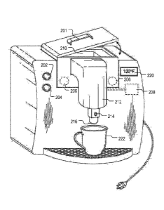
[0049]
Referring now to FIG. 2, a coffee preparation system according to one
embodiment
is shown. The coffee preparation system has a preparation chamber 210 having a
lid with a
handle 201 that the user may use to open and close the preparation chamber
210. The
preparation chamber 210 has one or more electrical heating cartridges 206
disposed in sufficient
proximity in the preparation chamber so as to apply heat to the chamber's
contents. The desired
beverage temperature may be selected by using one or more buttons 202, 204
disposed on the
front side of the beverage preparation system and the beverage preparation
system may also be
activated using buttons 202, 204 or another button (not shown). Although not
depicted in FIG. 2,
in some embodiments, the beverage preparation system may also have buttons for
setting a time
for completing a brew cycle in advance. Additionally, the beverage preparation
system may also
contain one or more process controllers, such as
proportional¨integral¨derivative (PID)
controllers, 220 connected to a display disposed on the front side of the
beverage preparation
system that display information to the user, such as the time or currently
selected temperature for
brewing the coffee beverage. The beverage preparation system may also contain
one or more
thermocouples 208 to regulate the temperature of the heat applied to the
preparation chamber
210, as described further herein. Once the beverage is heated to the proper
temperature, the
beverage may be drained through a spout 212 and outlet port 216 into a
receiving vessel 222,
such as a cup. The draining of the beverage through spout 212 and/or outlet
port 216 may be
controlled by a control valve within the spout 212, which, in certain
embodiments, may
controlled electronically by a heating control circuit to open when the coffee
reaches the desired
temperature or may be opened manually by the user pressing button 214. The
sizes of the
components and electrical specifications shown in FIG. 1 can be modified as
needed to
accommodate different sized starting materials (such as ice blocks of frozen
coffee), materials
used in manufacturing and desired heating times and cycles, and add-on
features.
17
Date Recue/Date Received 2023-10-27
[0050] Although not depicted, in some embodiments the preparation chamber
210 of the
coffee preparation system depicted in FIG. 2 may be comprised of two separate
preparation
chambers. Similar to the preparation chamber 210 shown in FIG. 2, a first
preparation chamber
(which may also be referred to as a melting chamber) may be used for heating a
block of frozen
liquid. The temperature applied to the melting chamber by electrical heating
cartridges 206 may
be controlled by one or more thermocouples 208 that regulate the heat applied
to the first
preparation chamber. A second preparation chamber (which may also be referred
to as a heating
chamber) may be disposed separately from melting chamber but in proximity to
the melting
chamber. The first and second preparation chamber may be in fluid
communication and
connected by a flow path, such as a through-hole or a channel connecting the
two chambers. As
the block of frozen liquid in the first preparation chamber melts due to the
heat being applied to
the first preparation chamber by the electrical heating cartridges 206, the
runoff will drain into
the through-hole or channel and pass into the second preparation chamber. The
preparation
chamber is utilized primarily for heating the liquid beverage to the desired
temperature for
consumption. Heat may be applied to the heating chamber by one or more
electrical heating
cartridges, which may be separate from the electrical cartridges utilized by
the melting chamber.
The heat applied to the heating chamber by the electrical cartridges may also
be controlled by
one or more thermocouples, which may be the same or separate thermocouples as
thermocouples.
[0051] During use, the first preparation chamber will receive a frozen ice
block of brewed
coffee through a lid or opening in the first preparation chamber. Heat is
selectively applied to
the first preparation chamber from electrical cartridges in order to melt the
frozen ice block of
the brewed beverage. As the frozen ice block melts, the runoff drains into the
second preparation
chamber and heat is likewise selectively applied to the second preparation
chamber from
electrical cartridges in order heat the beverage to the desired temperature
for consumption.
[0052] It should be noted that because the ice block is created according
to the methods
and processes described herein, it may be stored in an oxygen permeable
container or even an ice
cube nay like container that is openly exposed to oxygen on one side inasmuch
as the process
described herein forms a high quality ice barrier that reduces ingress of
oxygen into the beverage
once frozen. Thus, in certain embodiments, the frozen ice block may be removed
from the
18
Date Recue/Date Received 2023-10-27
oxygen permeable container or tray and placed in the preparation chamber such
that it is in direct
contact with the sidewalls of the heating chamber (or other surface to which
heat is applied). In
these embodiments, no cutting or puncturing of the packaging (e.g., via
needle), or specific
design of packaging to accommodate a needle to puncture the packaging to
create a drain hole, is
required. In addition, since the ice block maintains the reduced dissolve
oxygen content at, for
example, 2 PPM or below while frozen, there is no need for packaging having
specialized
oxygen barrier layers or properties (e.g., oxygen impermeable containers)
built into the
packaging, and which make recycling difficult. Further, because the ice block
maintains the
reduced dissolved oxygen content at, for example, 2 PPM or below while frozen,
there is also no
need for the addition of preservatives to the brewed beverage. Thus, coffee
beans having an
organic certification can maintain this certification when the brewed beverage
is prepared and
stored with the disclosed process as the beverage contains no added
preservatives.
[0053] In some embodiments, the use of different electrical cartridges to
apply heat to each
of the two preparation chambers allows the system to selectively apply
different levels of heat to
each of the two chambers. Beneficially, this approach allows the system to
apply a larger
amount of heat (e.g., full heat) to the first preparation chamber without
concern that there will be
localized boiling of the liquid runoff in the first preparation chamber
because the liquid runoff
will drain into the second preparation chamber as the frozen ice block melts.
Once the runoff
liquid has reached the second preparation chamber, the system may then
selectively apply heat to
the second preparation chamber from electrical cartridges in order heat the
beverage to the
desired temperature for consumption. As described in connection with the
embodiment depicted
in FIG. 2, the desired temperature for consumption may be selected using one
or more buttons
202, 204. In some embodiments, the system may automatically delay the heating
of the runoff
liquid in the second preparation chamber for a period of time in order to
allow sufficient time for
a portion of the runoff liquid to flow from the first preparation chamber to
the second preparation
chamber.
[0054] Referring now to FIG. 3, an exemplary process for using the coffee
beverage
preparation according to some embodiments is shown. At step 302, a consumer
will retrieve a
frozen brewed coffee ice block (such as those as described in U.S. Patent No.
9,307,777 by the
same inventor) from a freezer and remove the ice block from oxygen permeable
wrapper or
19
Date Recue/Date Received 2023-10-27
container step 304. At step 306, the ice block is then placed in the coffee
preparation system
chamber and the lid is closed. In certain embodiments, the oxygen permeable
wrapper or
container may be able to remain on the ice block and placed directly in the
preparation chamber
at step 306. In these embodiments, it is preferential to have a means to open
or puncture the
oxygen permeable wrapper or container before or after insertion into the
preparation chamber,
such that the liquid runoff may drain from the container. At step 308, the
consumer places a
coffee cup or other receptacle under the outlet port of the coffee preparation
system, and at step
310 the desired brewed beverage temperature is selected from the control panel
and then the
consumer presses the start button. At step 312, the coffee preparation system
will begin a power
cycle to melt the frozen coffee. The heater system can be selected to heat the
coffee as quickly
as possible (e.g., full power) until the melted coffee reaches near the
desired, set temperature.
The temperature is monitored by a thermocouple sensor located in the coffee
preparation
chamber. In another preferred embodiment, the melted coffee temperature is
controlled through
a PID controller. At step 314, an electronically controlled valve is opened at
the pre-selected
desired coffee temperature and the hot coffee in the preparation chamber is
allowed to flow into
the consumer's cup and is ready for consumption at block 316. The power to the
preparation
chamber is automatically stopped, the outlet valve is closed and the chamber
is ready to receive
another frozen ice block. In another embodiment, the outlet valve may also be
open manually
during any portion of the heating cycle, such as by the user pressing button
214 described in
connection with FIG. 2
[0055] In one embodiment, the preparation chamber is connected to an outlet
port in
which the liquid coffee flows to a cup or receptacle. The outlet port may have
a manual and/or
electronically operated valve that opens when the preset desired brewed coffee
temperature in
the preparation chamber is achieved. One benefit of such a system is that
coffee can actually be
brewed in the preparation chamber to have a cold or "iced coffee" temperature.
For the coldest
brewed coffee temperatures, it is envisioned that the outlet valve can be
opened immediately on
start of the preparation heating step and cold melted beverage will flow
directly into the
consumer's cup or other vessel as the frozen ice block begins to melt.
Similarly, in the two
chamber embodiment described in connection with FIG. 2, the cold or "iced
coffee" temperature
may be achieved by not having the second preparation apply heat at all and
allowing the runoff
liquid to flow directly in the consumer's cup or other vessel.
Date Recue/Date Received 2023-10-27
[0056] Referring now to FIG. 4, an exemplary process for using the coffee
beverage
preparation according to another embodiment is shown. At step 402, a consumer
will retrieve a
frozen brewed coffee ice block of coffee concentrate from the freezer. The
user removes the
concentrate from the oxygen permeable wrapper or container at step 404. At
step 406, the user
places the brewed coffee concentrate in the preparation chamber and the
consumer can add water
along with concentrate ice block to the preparation chamber. The water and ice
block are
warmed to generate a brewed coffee beverage with a brew strength determined by
the amount of
water added to the preparation chamber. In another embodiment, the preparation
system may
have two preparation chambers. One for heating the coffee concentrate and the
other for
receiving the liquid water. At step 408, the user places a receiving vessel
under the outlet port of
the preparation chamber. In some embodiments, at step 410, the user selects
the desired coffee
temperature, and the heating cycle begins. At step 412, the coffee beverage
preparation system
applies a heating cycle algorithm to heat the frozen ice block to the desired
temperature. At step
414, at the desired temperature, the outlet valve (or outlet valves, as the
case may be) for the
chamber is opened and the contents flow into a single container, vessel, or
cup and mix to form a
brewed coffee beverage that is ready to be consumed at step 416.
[0057] In further embodiments still, two preparation chambers may be
connected by a flow
path as described further in connection with FIG. 2. In this case, water may
be added to the first
or the second preparation chamber by the user or by the system itself. The
coffee beverage
preparation system may also apply two different heating cycle algorithms to
the two chambers at
step 412. The first heating cycle algorithm may be used to melt the frozen ice
block and the
second heating cycle algorithm may be used to heat runoff liquid to the
desired temperature. In
this embodiment, one valve may be utilized for allowing the contents to flow
into the container
or vessel.
[0058] Referring now to FIG. 5, an exemplary process for using the coffee
beverage
preparation according to another embodiment is shown. At step 502, a consumer
will retrieve a
frozen brewed coffee ice block having a frozen water interface from the
freezer. The user
removes the brewed coffee ice block having a frozen water interface from the
oxygen permeable
wrapper or container at step 504. At step 506, the user places the brewed
coffee ice block having
a frozen water interface in the preparation chamber. In this embodiment, the
user does not need
to add water to the preparation chamber as the water interface and
concentrated brewed coffee
21
Date Recue/Date Received 2023-10-27
will mix as the frozen ice block melts. The water interface and ice block are
warmed to generate
a brewed coffee beverage. At step 508, the user places a receiving vessel
under the outlet port of
the preparation chamber. In some embodiments, at step 510, the user selects
the desired coffee
temperature, and the heating cycle begins. At step 512, the coffee beverage
preparation system
applies a heating cycle algorithm to heat the frozen ice block to the desired
temperature. In
certain embodiments where two preparation chambers are used, one for melting
and one for
heating, the coffee beverage preparation system may apply two different
heating cycle
algorithms to the two chambers at step 512. The first heating cycle algorithm
may be used to
melt the frozen ice block and the second heating cycle algorithm may be used
to heat runoff
liquid to the desired temperature. At step 514, at the desired temperature,
the outlet valves for
the chamber is opened and the contents flow into the receiving vessel or cup
to form a brewed
coffee beverage that is ready to be consumed at step 516.
[0059] Referring now to FIG. 6, an exemplary process for using the coffee
beverage
preparation according to another embodiment is shown. At step 602, a consumer
will retrieve a
frozen brewed coffee ice block from the freezer, which may be, for example, a
6 fluid oz. frozen
brewed coffee ice block. The user removes the 6 fluid oz. brewed coffee ice
block from the
oxygen permeable wrapper or container at step 604. At step 606, the user
places the 6 fluid oz.
brewed coffee ice block in the preparation chamber. At step 608, the user
places a receiving
vessel under the outlet port of the preparation chamber. In some embodiments,
at step 610, the
user selects the desired coffee temperature, and the heating cycle begins.
[0060] At step 612, the coffee beverage preparation system applies a
heating cycle
algorithm to heat the frozen ice block to the desired temperature. In this
embodiment, the
heating cycle algorithm comprises a predetermined number of intervals in which
the
thermocouple regulates the heat applied to the preparation system such that
the beverage
preparation system provides heat to the preparation system at 20 % full power
for 20 seconds,
after which power is then increased to 50% full power for next 30 seconds, and
then full power is
applied until desired temperature reached, although a person of skill in the
art would recognize
that these timeframes and percentages are merely illustrative and variations
may made without
departing from the scope of the present disclosure. In any event, one non-
limiting consideration
of the heating cycle algorithm is to prevent localized boiling of the coffee
beverage in the
preparation chamber as the frozen ice block begins to melt. In this way,
certain embodiments
22
Date Recue/Date Received 2023-10-27
may also include a stirrer or agitator in the preparation chamber to assist in
achieving more
uniform temperature throughout the melting beverage mixture and to deliver the
heat from side
walls into the ice block more efficiently.
[0061] Although not shown in FIG. 6, in certain embodiments where two
preparation
chambers are used, one for melting and one for heating, the coffee beverage
preparation system
may apply two different heating cycle algorithms to the two chambers at step
612. The first
heating cycle algorithm may be used to melt the frozen ice block. Because the
runoff from the
frozen ice block will pass into the second preparation chamber in this
embodiment, there is less
concern over localized boiling of the coffee beverage in the first preparation
chamber as the
frozen ice block begins to melt. Accordingly, the first heating algorithm may
apply full or nearly
full power to the first preparation chamber in order to melt the ice. A second
heating cycle
algorithm (which may be a sub-part of the first heating cycle algorithm) may
be used to heat
runoff liquid to the desired temperature. For example, the second heating
algorithm may delay a
short period of time after the first heating algorithm begins in order to
allow the runoff to begin
reaching the second preparation chamber and then apply a steady level of heat
to the second
preparation chamber. In some embodiments, the second heating algorithm may
apply a
gradually increasing level of heat the second preparation chamber, such as 10-
30% of full power
for a period of 20 seconds, and then increase the power to 20-50% or even to
full power until the
desired temperature is reached. Again, a person of skill in the art would
recognize that these
timeframes and percentages are merely illustrative and variations may made
without departing
from the scope of the present disclosure.
[0062] Referring again to FIG. 6, at step 614, the outlet valves for the
chamber opens at the
desired temperature and the contents flow into the receiving vessel or cup to
form a brewed
coffee beverage that is ready to be consumed at step 616.
[0063] Although features may be described herein with reference to a
particular
embodiment or Figure, one skilled in the art would understand that the same or
similar features
could be used in connection with the additional embodiments described herein.
Thus, reference
to a particular embodiment or Figure is not to be construed as limiting in any
way.
[0064] In addition to coffee beverages, it is also envisioned that teas and
other brewed
beverages of the like can be prepared by the system described in this
disclosure.
23
Date Recue/Date Received 2023-10-27
[0065] In some embodiments, liquid pre-brewed cold coffee (not frozen) can
also be added
to the preparation chamber and heated to desired temperature, or can be mixed
with frozen
brewed coffee in the preparation chamber and heated to the desired
temperature.
[0066] In other embodiments the consumer can add a small amount of water
(approximately 10-15% of the volume of the ice block) with the regular brew
strength ice block
to the preparation chamber. The liquid water can act as a temperature
regulator to prevent the
coffee compounds located at the surface of the ice block from being over
heated during the initial
heating phase.
[0067] In other embodiments the heating power percentage, or duty cycle, is
adjusted
during the preparation phase such that the heating power is gradually
increased in either a
stepwise fashion or in a linear fashion as the ice block melts to prevent
localized boiling of the
brewed coffee melt. The brewer can use PID control system to regulate the
heater power and use
thermocouple to monitor the coffee temperature during the heating step and
feedback that
temperature data to the PID controller.
[0068] The mechanism for supplying heat to the preparation chamber may be
electrical
cartridges and PID controllers, such as those supplied by WATLOW INC. , wired
heating
elements, or by infrared lamps, or microwave generator, convection heating, or
inductively
coupled heating or other energy sources capable of melting ice and the means
to control the
heating rate. The heating power will be sufficient to transform a 6 fluid
ounce single serve
coffee ice block to a hot brewed beverage in a consumer's cup in less than 5
minutes and in some
cases, preferably in less than 2 minutes from start of the heating phase.
[0069] In another preferred embodiment, the beverage system includes a
heating control
circuit that implements a heating cycle control algorithm is designed to
control the percentage
power so as to avoid localized boiling of the small amount of liquid coffee in
the melt during the
initial heating preparation step. As more of the ice block is melted, the
power supplied to the
preparation chamber can be increased. Nearing the complete melting of the ice
block the power
is increased to full power so as to reach the target coffee temperature as
soon as possible. For
example, in the embodiment shown in FIG. 6, the heating cycle control
algorithm uses an initial
heating percentage power of approximately 20 percent of full power for 30
seconds, then self-
adjusts to a percentage of full power of approximately 50 percent for 30
seconds, and self-adjusts
to full power for the remainder of the heating cycle, although a person of
skill in the art would
24
Date Recue/Date Received 2023-10-27
recognize that these times and percentages of power can be varied to achieve
the melting of the
ice block and heating of the beverage to the desired brewed beverage
temperature with a certain
time frame. In another embodiment, the desired time for full heating the ice
block is 5 minutes
or less to achieve the desired brewed beverage temperature and in another
embodiment the time
is targeted to be 2 minutes or less to reach the desired temperature. In the
latter scenario, a more
aggressive algorithm schedule can be taken to achieve full heating of the
beverage to the desired
temperature within the target timeframe.
[0070] In a preferred embodiment, the preparation chamber is made from
aluminum to
improve heat conductivity and distribution to the frozen ice block. In another
embodiment the
bottom of the heating chamber is aluminum and the side walls are made of heat
resistant plastic
that are thermally isolated from the bottom heating element.
[0071] The illustrations of the embodiments described herein are intended
to provide a
general understanding of the structure of the various embodiments. The
illustrations are not
intended to serve as a complete description of all of the elements and
features of apparatus and
systems that utilize the structures or methods described herein. Many other
embodiments may
be apparent to those of skill in the art upon reviewing the disclosure. Other
embodiments may be
utilized and derived from the disclosure, such that structural and logical
substitutions and
changes may be made without departing from the scope of the disclosure.
Additionally, the
illustrations are merely representational and may not be drawn to scale.
Certain proportions
within the illustrations may be exaggerated, while other proportions may be
minimized.
Accordingly, the disclosure and the figures are to be regarded as illustrative
rather than
restrictive.
[0072] One or more embodiments of the disclosure may be referred to herein,
individually
and/or collectively, by the term "invention" merely for convenience and
without intending to
voluntarily limit the scope of this application to any particular invention or
inventive concept.
Moreover, although specific embodiments have been illustrated and described
herein, it should
be appreciated that any subsequent arrangement designed to achieve the same or
similar purpose
may be substituted for the specific embodiments shown. This disclosure is
intended to cover any
and all subsequent adaptations or variations of various embodiments.
Combinations of the above
Date Recue/Date Received 2023-10-27
embodiments, and other embodiments not specifically described herein, will be
apparent to those
of skill in the art upon reviewing the description.
[0073] The Abstract of the Disclosure is provided and is submitted with the
understanding
that it will not be used to interpret or limit the scope or meaning of the
claims. In addition, in the
foregoing Detailed Description, various features may be grouped together or
described in a
single embodiment for the purpose of streamlining the disclosure. This
disclosure is not to be
interpreted as reflecting an intention that the claimed embodiments require
more features than
are expressly recited in each claim. Rather, as the following claims reflect,
inventive subject
matter may be directed to less than all of the features of any of the
disclosed embodiments.
[0074] The above disclosed subject matter is to be considered illustrative,
and not
restrictive. Thus, to the maximum extent allowed, the scope of the present
invention is to be
determined by the broadest permissible interpretation of the specification as
a whole. While
various embodiments of the invention have been described, it will be apparent
to those of
ordinary skill in the art that many more embodiments and implementations are
possible within
the scope of the invention.
26
Date Recue/Date Received 2023-10-27