Note: Descriptions are shown in the official language in which they were submitted.
CABLE STRUCTURE, POWER CORD STRUCTURE, AND ELECTRICAL DEVICE
=
Field of the Invention
The present invention relates to the field of electric appliances, and in
particular, to a
cable structure, a power cord structure and an electrical device.
Background of the Invention
An electrical device is connected to a network or interconnected with other
equipment
through different communication modules. The communication modules include,
but not
limited to, WIFI modules, Bluetooth modules, ZIGBEE modules, and the working
principle of the communication modules, is to transmit information through
wireless
signals. The majority of communication modules in related technical solutions
adopt
microwave communication (microwave: electromagnetic wave of 300 MHz to 300
GHz),
the transmission and reception of the wireless signals depend on antennas with
specific
shapes, and the lower the transmitting and receiving frequency of the
communication is,
the larger the appearance size of the necessary antenna is. The wireless
signals are
difficult to penetrate through metals and will be shielded by the metals; the
wireless
signals will be interfered by noise with the same frequency range, so that the
communication cannot be carried out; the strength of the wireless signal
decays quickly
with distance; the communication modules are electronic components and require
specific temperature ranges, humidity ranges and very small electromagnetic
interference to work normally; and the antennas of the communication modules
must be
CA 3018899 2019-09-24
CA 03018899 2018-09-25
away from the metals. The structure design of the communication module on the
electrical device in related art mainly includes the following several
manners:
The communication module is designed in the electrical device. In this manner,
the
communication module will be shielded by a metal shell of the electrical
device and
will also be interfered by a motor, a circuit board, coils, a magnetron and
the like in
the household appliance.
The communication module is designed on the shell of the electrical device. In
this
manner, the communication ability of the communication module will be
influenced
by the metal shell of the electrical device and will be affected by the high
temperature produced by the electrical device, and this installation manner
will
affect the appearance consistency of the household appliance and increase the
overall size of the household appliance, thereby being not beautiful or
practical.
The communication module is designed in the household appliance, and the
antenna of the communication module is led out alone and is designed at the
outside of the household appliance. This manner will affect the appearance
consistency of the household appliance, and as the additional antenna portion
is
increased at the outside of the household appliance, the size of the household
appliance is increased, thereby being not beautiful or practical. Moreover,
the
antenna mounted at the outside is liable to damage.
In summary, due to the existing structure design of the communication module,
the
communication module is vulnerable to being shielded, vulnerable to high
temperature and vulnerable to the interference of other electronic devices,
and the
appearance consistency of the household appliance is also affected, thereby
being
not beautiful or practical.
Summary of the Invention
In order to solve at least one of the above technical problems, the embodiment
of
2
CA 03018899 2018-09-25
one aspect of the present invention provides a cable structure.
The embodiment of a second aspect of the present invention provides a power
cord
structure.
The embodiment of yet another aspect of the present invention provides an
electrical device.
In view of this, according to the embodiment of one aspect of the present
invention,
the present invention provides a cable structure, applied to an electrical
device, and
characterized by including: a power cord; a shell arranged on the power cord;
and
an antenna arranged in the shell.
The cable structure provided by the present invention includes the power cord
and
the shell, the shell is arranged on the power cord, and the antenna is
arranged in the
shell. As the antenna is arranged in the shell and does not need to be exposed
to
the outside, so that the antenna can be protected from being damaged easily,
and
the antenna can work in a good environment, thereby guaranteeing the working
reliability and stability of the antenna; meanwhile, the shell is arranged on
the power
cord, so the electrical device does not need to be provided with additional
antenna
devices, thereby guaranteeing the beauty of the overall appearance,
guaranteeing
convenience for carrying and improving the user experience. Further, the shell
is
arranged on the power cord, the position of the shell can be at the middle,
the front
or different positions satisfying requirements of the power cord, therefore
different
needs of the user can be satisfied, and the application range is wide.
In addition, the cable structure in the above-mentioned embodiment provided by
the
present invention can further have the following additional technical
features:
In the above-mentioned technical solution, preferably, the cable structure
further
includes: a communication module arranged in the shell and connected with the
antenna.
In the technical solution, the communication module is arranged in the shell
and is
3
CA 03018899 2018-09-25
arranged on the power cord together with the antenna, thereby not only being
able
to shorten the connection path between the communication module and the
antenna
and facilitate signal transmission, but also avoiding increasing additional
communication modules and antenna portions at the outside of the electrical
device
to increase the size of the electrical device, and guaranteeing the appearance
consistency, beauty and practicability of the electrical device; meanwhile, as
the
communication module is arranged on the power cord, the communication module
can be far away from the electrical device, so the communication ability of
the
communication module will not be shielded by the metal shell of the electrical
device,
and will not be affected by a motor, a circuit board, coils, a magnetron and
other
factors in the electrical device, or affected by the high temperature caused
by the
operation of the equipment, accordingly the communication module works in a
good
environment, and the working reliability and stability of the communication
module
are guaranteed.
In the above-mentioned technical solution, preferably, the cable structure
further
includes: a conducting wire, wherein one end of the conducting wire is
connected
with the communication module or the antenna, and the other end of the
conducting
wire is connected with the electrical device.
In the technical solution, on the one hand, when both the communication module
and the antenna are arranged in the shell, the antenna is connected with the
communication module, and the antenna quickly transmits a received signal to
the
communication module and transmits the signal to the electrical device through
the
conducting wire so as to realize the intelligent control of the electrical
device. On the
other hand, the communication module and the antenna are not located on the
same
position, the communication module can be designed in the electrical device or
on
the shell, the antenna of the communication module is led out by the
conducting wire
and is designed on the power cord, and the antenna transmits the signal to the
4
CA 03018899 2018-09-25
communication module of the electrical device through the conducting wire
after
receiving the signal so as to realize the intelligent control of the
electrical device.
In the above-mentioned technical solution, preferably, the shell is detachably
mounted on the power cord.
In the technical solution, as the shell is detachably mounted on the power
cord, it is
convenient to install and detach, thereby facilitating the maintenance and
inspection
and improving the efficiency of the after-sales service. Further, when the
communication module or the antenna arranged in the shell is damaged, only the
shell needs to be replaced, thereby avoiding the replacement of the intact
power
cord, reducing the cost, improving the utilization rate of the power cord and
improving the satisfaction of use of the user.
In the above-mentioned technical solution, preferably, the power cord includes
a
first portion and a second portion separated from the first portion; the first
portion is
connected with the second portion by a connecting element; and the connecting
element is arranged in the shell.
In the technical solution, the power cord includes the first portion and the
second
portion separated from the first portion, and the first portion and the second
portion
are connected by the connecting element that is arranged in the shell, so the
shell
can be located at any position of the power cord, accordingly different needs
of the
user are satisfied, and the application range is wide. Further, the power cord
includes the first portion and the second portion, and the lengths of the
first portion
and the second portion can be set according to the needs of the user, thereby
avoiding waste and reducing the cost, and thus the satisfaction degree of use
of the
user is improved.
In the above-mentioned technical solution, preferably, the connecting element
includes a power cord docking interface arranged at the end part of the shell,
and a
power cord interface arranged on the first portion and the second portion of
the
CA 03018899 2018-09-25
power cord and matched with the power cord docking interface.
In the technical solution, by means of the cooperation of the power cord
docking
interface arranged at the end part of the shell and the power cord interface
arranged
on the first portion and the second portion of the power cord, the connection
of the
first portion of the power cord with the shell and the connection of the
second portion
of the power cord with the shell are realized, and then the power cords of the
two
portions are connected through the shell. When the portions of the power cord
are
damaged or the communication module and the antenna are damaged, only the
power cord of the damaged portion or the communication module and the antenna
need to be replaced, thereby avoiding the replacement of the power cord of the
other intact portion, reducing the cost, improving the utilization rate of the
power
cord and improving the satisfaction degree of use of the user.
In the above-mentioned technical solution, preferably, a cover body is
arranged on
the shell, and the cover body is detachably mounted on the shell.
In the technical solution, as the cover body is arranged on the shell, and the
cover
body is detachably mounted on the shell, when any one of the communication
module, the antenna and the conducting wire in the shell is damaged,
troubleshooting is facilitated for maintenance and component replacement.
In the above-mentioned technical solution, preferably, the conducting wire and
the
power cord are of an integrated structure, and the conducting wire is
integrated in
the power cord.
In the technical solution, the conducting wire for connecting the
communication
module with the electrical device is integrated with the power cord, so that
the
connecting circuits of the communication module and the power supply with the
electrical device are merged, the circuit layout is more neat, meanwhile a
rubber
coating structure of the power cord protects the conducting wire, thereby not
only
prolonging the service life of the conducting wire, but also guaranteeing the
safety of
6
CA 03018899 2018-09-25
daily use of the user.
In any one of the above-mentioned technical solutions, preferably, the shell
is
arranged at an end part or a middle portion of the power cord.
In the technical solution, the shell is arranged at the end part or the middle
portion of
the power cord, the shell is arranged at a proper position according to the
specific
use environment and function of the electrical device so as to avoid the
influence of
the metal shell of the electrical device, the high operation temperature,
electromagnetic interference and other factors.
In any one of the above-mentioned technical solutions, preferably, the shell
is an
insulating shell; and both the power cord and the conducting wire are coated
with
insulating layers.
In the technical solution, the interference of external factors on the
communication
module is avoided by the insulating shell, and further, the outside of both
the power
cord and the conducting wire is coated with the insulating layers, so a strong
wire is
separated from a weak wire, and the conducting wire is not interfered by the
power
cord.
In any one of the above-mentioned technical solutions, preferably, the power
cord at
least includes a power live wire and a power zero line.
In the technical solution, on the one hand, the power cord is a 3PIN power
cord and
includes the power live wire, the power zero line and a power ground line; and
on
the other hand, the power cord is a 2PIN power cord and includes the power
live
wire and the power zero line. Different structures of the power cord can
satisfy
different needs of the user, and thus the application range is wide.
According to the embodiment of the second aspect of the present invention, a
power
cord structure is further provided, applied to an electrical device,
including: a power
cord plug; and the cable structure in any one of the above-mentioned technical
solutions; and the power cord plug is connected with the cable structure.
7
CA 03018899 2018-09-25
The power cord structure provided by the embodiment of the second aspect of
the
present invention includes the power cord plug and the cable structure in any
one of
the above-mentioned technical solutions, therefore the power cord structure
has all
the beneficial effects of the cable structure, and the cable structure is
connected
with the electrical device through the power cord plug so as to guarantee the
power
supply and the connection between the communication module and the electrical
device.
In the above-mentioned technical solution, preferably, the power cord
structure
further includes a power cord connector, and the power cord connector is
connected
with one end of the cable structure opposite to the power cord plug.
In the technical solution, one end of the cable is connected with the power
cord plug,
the other end of the cable is connected with the power cord connector, due to
the
arrangement of the power cord connector, the detachment and the deployment of
the power cord structure are facilitated, meanwhile when any component in the
power cord structure is damaged, a new power cord structure is just replaced,
thereby generating no influence on the use of the overall machine of the
electrical
device, reducing the cost and improving the satisfaction degree of use of the
user.
In the above-mentioned technical solution, preferably, the power cord
connector
includes: a power cord interface connected with the power cord; and a data
line
interface connected with the conducting wire.
In the technical solution, the power cord connector is provided with the power
cord
interface and the data line interface, which can be respectively connected
with the
power cord and the conducting wire, therefore the power supply is connected
with
the electrical device through the power cord to provide electric power for the
electrical device, and the communication module or the antenna is connected
with
the electrical device to transmit signals so as to realize the intelligent
control of the
electrical device.
8
CA 03018899 2018-09-25
According to the embodiment of yet another aspect of the present invention, an
electrical device is further provided, including: the cable structure in any
one of the
above-mentioned technical solutions; or the power cord structure in any one of
the
above-mentioned technical solutions.
The electrical device provided by the embodiment of yet another aspect of the
present invention includes the cable structure provided by the embodiment of
the
first aspect of the present invention or the power cord structure provided by
the
embodiment of the second aspect, the communication module or the antenna can
be hermetically arranged on the power cord, so the antenna does not need to be
exposed to the outside and is unlikely to be damaged, and the communication
module is also far away from the electrical device, so the communication
ability of
the communication module will not be shielded by the metal shell of the
electrical
device, and will not be affected by the motor, the circuit board, the coils,
the
magnetron and other factors in the electrical device, or affected by the high
temperature caused by the operation of the equipment, accordingly the
communication module or the antenna works in a good environment, and the
working reliability and stability of the communication module or the antenna
are
guaranteed; no additional size is added to the electrical device, thereby
guaranteeing the beauty of the overall appearance, guaranteeing convenience
for
carrying and improving the user experience; meanwhile, the communication
module
having complete functions can satisfy comprehensive needs of the user for all
kinds
of electrical device, thereby improving the application range of the power
cord
structure; and the detachable power cord structure reduces the maintenance and
component replacement cost of the electrical device, prolongs the service life
of the
overall machine of the electrical device and improves the satisfaction degree
of use
of the user.
In the above-mentioned technical solution, preferably, the electrical device
is a
9
CA 03018899 2018-09-25
household appliance, including: a microwave oven, a microwave oven, an oven
and
a water heater.
In the technical solution, the cable structure or the power cord structure is
applied to
the microwave oven, the microwave oven, the oven and the water heater, the
user
can conveniently and remotely control these household appliances, including,
but
not limited to, opening and closing the household appliances, setting expected
values, adjusting operation modes and the like, and can also transmit menus to
the
microwave oven, the microwave oven and the oven for automatic cooking.
Additional aspects and advantages of the present invention will become
apparent
from the following description, or may be learned by the practice of the
present
invention.
Brief Description of the Drawings
The foregoing and/or additional aspects and advantages of the present
invention will
become apparent and understandable from the following description of the
embodiments in conjunction with the accompanying drawings, wherein:
Fig. 1 is a schematic diagram of a power cord structure in an embodiment of
the
present invention;
Fig. 2 is a schematic diagram of a power cord structure in an embodiment of
the
present invention;
Fig. 3 is a schematic diagram of a power cord structure in an embodiment of
the
present invention;
Fig. 4 is a structural schematic diagram of a power cord plug in an embodiment
of
the present invention.
The corresponding relationship between reference signs in Fig. 1 to Fig. 4 and
component names is as follows:
1 power cord structure, 10 cable structure, 102 shell, 104 antenna, 106
CA 03018899 2018-09-25
communication module, 108 power cord, 110 conducting wire, 112 power cord
docking interface, 114 power cord interface, 12 power cord plug, 14 power cord
connector, 142 power cord interface, and 144 data line interface.
Detailed Description of the Embodiments
In order that the above-mentioned objectives, features and advantages of the
present
invention can be understood more clearly, a further detailed description of
the present
invention will be given below in combination with the accompanying drawings
and
embodiments. It should be noted that, in the absence of a conflict, the
embodiments of
the present application and the features in the embodiments can be combined
with each
other.
A lot of specific details are set forth in the following description so as to
fully
understand the present invention, but the present invention may also be
implemented in other ways other than those described herein, and thus the
protection scope of the present invention is not limited to the specific
embodiments
disclosed below.
A cable structure according to some embodiments of the present invention will
be
described below with reference to Fig. 1 to Fig. 4.
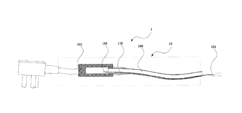
As shown in Fig. 1, the present invention provides a cable structure 10,
applied to an
electrical device, and characterized by including: a power cord 108; a shell
102
arranged on the power cord; and an antenna 104 arranged in the shell 102.
The cable structure 10 provided by the present invention includes the power
cord
108 and the shell 102, the shell 102 is arranged on the power cord 108, and
the
antenna 104 is arranged in the shell 102. As the antenna 104 is arranged in
the shell
102 and does not need to be exposed to the outside, so that the antenna 104
can be
protected from being damaged easily, and the antenna 104 can work in a good
11
CA 03018899 2018-09-25
environment, thereby guaranteeing the working reliability and stability of the
antenna 104; meanwhile, the shell 102 is arranged on the power cord, so the
electrical device does not need to be provided with additional antenna 104
devices,
thereby guaranteeing the beauty of the overall appearance, guaranteeing
convenience for carrying and improving the user experience. Further, the shell
102
is arranged on the power cord, the position of the shell 102 can be at the
middle, the
front or different positions satisfying requirements of the power cord,
therefore
different needs of the user can be satisfied, and the application range is
wide.
In addition, the cable structure 10 in the above-mentioned embodiment provided
by
the present invention can further have the following additional technical
features:
In an embodiment of the present invention, preferably, as shown in Fig. 2, the
cable
structure further includes: a communication module 106 arranged in the shell
102
and connected with the antenna 104.
In the embodiment, the communication module 106 is arranged in the shell 102
and
is arranged on the power cord 108 together with the antenna 104, thereby not
only
being able to shorten the connection path between the communication module 106
and the antenna 104 and facilitate signal transmission, but also avoiding
increasing
additional communication modules 106 and antenna 104 portions at the outside
of
the electrical device to increase the size of the electrical device, and
guaranteeing
the appearance consistency, beauty and practicability of the electrical
device;
meanwhile, as the communication module 106 is arranged on the power cord, the
communication module 106 can be far away from the electrical device, so the
communication ability of the communication module 106 will not be shielded by
the
metal shell of the electrical device, and will not be affected by a motor, a
circuit
board, coils, a magnetron and other factors in the electrical device, or
affected by
the high temperature caused by the operation of the equipment, accordingly the
communication module 106 works in a good environment, and the working
reliability
12
CA 03018899 2018-09-25
and stability of the communication module 106 are guaranteed.
Further, for example, a microwave oven includes the communication module 106,
if
the communication module 106 works at 2.412 GHz to 2.472 GHz, and the
microwave center frequency of the microwave oven is 2.45GHz, then the
microwave
oven will generate the same frequency interference on the communication module
106, the communication module 106 is arranged in the shell 102 on the power
cord
108 located at the outside of the microwave oven, so the communication module
106 is far away from the microwave oven, the same frequency interference of
the
communication module 106 generated by the microwave oven is effectively
reduced,
or the microwave oven cannot interfere the communication module 106, therefore
the communication ability of the communication module 106 will not be affected
by
the motor, the circuit board, the coils, the magnetron and other factors in
the
electrical device, and the satisfaction degree of use of the user is improved.
Further,
for example, a water heater includes the communication module 106, the shell
of the
water heater is generally of a full-metal sealed structure, if the
communication
module 106 is designed in the water heater, the communication module 106 will
be
shielded by the metal and cannot work, the communication module 106 is
arranged
in the shell 102 on the power cord 108 located at the outside of the water
heater, so
the communication module 106 is far away from the water heater, and the
interference of the communication module 106 generated by a metal outer wall
of
the water heater is effectively avoided, therefore the communication ability
of the
communication module 106 will not be shielded by the metal shell of the
electrical
device, and the satisfaction degree of use of the user is improved.
Further, for example, an oven includes the communication module 106, the
majority
of the working temperatures of the oven are higher than 200 degrees
centigrade, the
oven continuously dissipates heat, so the surrounding of the shell of the oven
is a
high temperature area, which does not satisfy the specific temperature needs
for the
13
CA 03018899 2018-09-25
working of the communication module 106, thereby affecting the working effect
of
the communication module 106, as the communication module 106 is arranged in
the shell 102 on the power cord 108 away from the oven and located at the
outside
of the oven, the communication module 106 works in a good environment, and the
working reliability and stability of the communication module 106 are
guaranteed.
Further, for example, an air conditioner includes the communication module
106,
and the antenna 104 connected with the communication module 106 is led to the
outside of the air conditioner, thereby affecting the overall reliability and
beauty of
the air conditioner, accordingly the communication module 106 is arranged in
the
shell 102 on the power cord 108 located at the outside of the air conditioner,
thereby
increasing no additional size of the electrical device, guaranteeing the
beauty of the
overall appearance, being higher in practicability and improving the
satisfaction
degree of use of the user.
In an embodiment of the present invention, preferably, as shown in Fig. 1 to
Fig. 3,
the cable structure further includes: a conducting wire 110, one end of the
conducting wire 110 is connected with the communication module 106 or the
antenna 104, and the other end of the conducting wire is connected with the
electrical device.
In the embodiment, on the one hand, when the communication module 106 and the
antenna 104 are arranged in the shell 102, the antenna 104 is connected with
the
communication module 106, and the antenna 104 quickly transmits a received
signal
to the communication module 106 and transmits the signal to the electrical
device
through the conducting wire 110 so as to realize the intelligent control of
the
electrical device. On the other hand, the communication module 106 and the
antenna 104 are not located on the same position, the communication module 106
can be designed in the electrical device or on the shell, the antenna 104 of
the
communication module 106 is led out by the conducting wire 110 and is designed
on
14
CA 03018899 2018-09-25
the power cord 108, the antenna 104 transmits the signal to the communication
module 106 of the electrical device through the conducting wire 110 after
receiving
the signal so as to realize the intelligent control of the electrical device.
In an embodiment of the present invention, preferably, as shown in Fig. 3, the
shell
102 is detachably mounted on the power cord.
In the embodiment, as the shell 102 is detachably mounted on the power cord
108, it
is convenient to install and detach, thereby facilitating the maintenance and
inspection and improving the efficiency of the after-sales service. Further,
when the
communication module 106 or the antenna 104 arranged in the shell 102 is
damaged, only the shell 102 needs to be replaced, thereby avoiding the
replacement of the intact power cord 108, reducing the cost, improving the
utilization
rate of the power cord and improving the satisfaction degree of use of the
user.
In an embodiment of the present invention, preferably, as shown in Fig. 3, the
power
cord 108 includes a first portion and a second portion separated from the
first
portion; the first portion is connected with the second portion by a
connecting
element; and the connecting element is arranged in the shell 102.
In the embodiment, the power cord 108 includes the first portion and the
second
portion separated from the first portion, and the first portion and the second
portion
are connected by the connecting element that is arranged in the shell 102, so
the
shell 102 can be located at any position of the power cord 108, accordingly
different
needs of the user are satisfied, and the application range is wide. Further,
the power
cord 108 includes the first portion and the second portion, and the lengths of
the first
portion and the second portion can be set according to the needs of the user,
thereby avoiding waste and reducing the cost, and thus the satisfaction degree
of
use of the user is improved.
In an embodiment of the present invention, preferably, as shown in Fig. 3, the
connecting element includes a power cord docking interface 112 arranged at the
CA 03018899 2018-09-25
end part of the shell 102, and a power cord interface 142 arranged on the
first
portion and the second portion of the power cord 108 and matched with the
power
cord docking interface 112.
In the embodiment, by means of the cooperation of the power cord docking
interface
112 arranged at the end part of the shell 102 and the power cord interface 142
arranged on the first portion and the second portion of the power cord 108,
the
connection of the first portion of the power cord with the shell 102 and the
connection of the second portion of the power cord with the shell 102 are
realized,
and then the power cords 108 of the two portions are connected through the
shell
102. When the portions of the power cord 108 are damaged or the communication
module 106 and the antenna 104 are damaged, only the power cord 108 of the
damaged portion or the communication module 106 and the antenna 104 need to be
replaced, thereby avoiding the replacement of the power cord of the other
intact
portion, reducing the cost, improving the utilization rate of the power cord
108 and
improving the satisfaction degree of use of the user.
In an embodiment of the present invention, preferably, a cover body is
arranged on
the shell 102, and the cover body is detachably mounted on the shell 102.
In the embodiment, as the cover body is arranged on the shell 102, and the
cover
body is detachably mounted on the shell 102, when any one of the communication
module 106, the antenna 104 and the conducting wire 110 in the shell 102 is
damaged, troubleshooting is facilitated for maintenance and component
replacement.
In an embodiment of the present invention, preferably, as shown in Fig. 4, the
conducting wire 110 and the power cord 108 are of an integrated structure, and
the
conducting wire 110 is integrated in the power cord 108.
In the embodiment, the conducting wire 110 for connecting the communication
module 106 with the electrical device is integrated with the power cord, so
that the
16
CA 03018899 2018-09-25
connecting circuits of the communication module 106 and the power supply with
the
electrical device are merged, the circuit layout is more neat, meanwhile a
rubber
coating structure of the power cord 108 protects the conducting wire 110,
thereby
not only prolonging the service life of the conducting wire 110, but also
guaranteeing
the safety of daily use of the user.
In an embodiment of the present invention, preferably, the shell 102 is
arranged at
an end part or a middle portion of the power cord.
In the embodiment, the shell 102 is arranged at the end part or the middle
portion of
the power cord 108, the shell is arranged at a proper position according to
the
specific use environment and function of the electrical device so as to avoid
the
influence of the metal shell 102 of the electrical device, the high operation
temperature, electromagnetic interference and other factors.
In an embodiment of the present invention, preferably, the shell 102 is an
insulating
shell 102; and both the power cord and the conducting wire 110 are coated with
insulating layers.
In the technical solution, the interference of external factors to the
communication
module 106 is avoided by the insulating shell 102, and further, the outside of
both
the power cord 108 and the conducting wire 110 is coated with the insulating
layers,
so a strong wire is separated from a weak wire, and the conducting wire 110 is
not
interfered by the power cord.
In an embodiment of the present invention, preferably, the power cord 108 at
least
includes a power live wire and a power zero line.
In the embodiment, on the one hand, the power cord 108 is a 3PIN power cord
and
includes the power live wire, the power zero line and a power ground line; and
on
the other hand, the power cord 108 is a 2PIN power cord and includes the power
live
wire and the power zero line. Different numbers of the power cord interfaces
142 can
satisfy different needs of the user, and thus the application range is wide.
Further,
17
CA 03018899 2018-09-25
there may be 4 data line interfaces 144, meanwhile four conducting wires 110
are
connected, further the number of the data line interfaces 144 can be any
number
satisfying the needs, and different forms of the data line interfaces 144 can
satisfy
different needs of the user, and thus the application range is wide.
According to the embodiment of the second aspect of the present invention, a
power
cord structure 1 is further provided, applied to an electrical device,
including: a
power cord plug 12; and the cable structure 10 in any one of the above-
mentioned
technical solutions; and the power cord plug 12 is connected with the cable
structure
10.
The power cord structure 1 provided by the embodiment of the second aspect of
the
present invention includes the power cord plug 12 and the cable structure 10
in any
one of the above-mentioned technical solutions connected with the power cord
plug,
therefore the power cord structure has all the beneficial effects of the cable
structure
10, and the cable structure 10 is connected with the electrical device through
the
power cord plug 12 so as to guarantee the power supply and the connection
between the communication module 106 and the electrical device.
In an embodiment of the present invention, preferably, as shown in Fig. 4, the
power
cord structure further includes a power cord connector 14, and the power cord
connector 14 is connected with one end of the cable structure 10 opposite to
the
power cord plug 12.
In the embodiment, one end of the cable is connected with the power cord plug
12,
the other end of the cable is connected with the power cord connector 14, due
to the
arrangement of the power cord connector 14, the detachment and the deployment
of
the power cord structure 1 are facilitated, meanwhile when any component in
the
power cord structure 1 is damaged, a new power cord structure 1 is just
replaced,
thereby generating no influence on the use of the overall machine of the
electrical
device, reducing the cost and improving the satisfaction degree of use of the
user.
18
CA 03018899 2018-09-25
In an embodiment of the present invention, preferably, as shown in Fig. 4, the
power
cord connector 14 includes: a power cord interface 142 connected with the
power
cord; and a data line interface 144 connected with the conducting wire 110.
In the embodiment, the power cord connector is provided with the power cord
interface 142 and the data line interface 144, which can be respectively
connected
with the power cord 108 and the conducting wire 110, therefore the power
supply is
connected with the electrical device through the power cord 108 to provide
electric
power for the electrical device, and the communication module 106 or the
antenna
104 is connected with the electrical device to transmit signals so as to
realize the
intelligent control of the electrical device.
According to the embodiment of yet another aspect of the present invention, an
electrical device is further provided, including: the cable structure 10 in
any one of
the above-mentioned technical solutions; or the power cord structure 1 in any
one of
the above-mentioned technical solutions.
The electrical device provided by the embodiment of yet another aspect of the
present invention includes the cable structure 10 provided by the embodiment
of
one aspect of the present invention or the power cord structure 1 provided by
the
embodiment of the second aspect, the communication module 106 or the antenna
104 can be hermetically arranged on the power cord 108, so the antenna 104
does
not needs to be exposed to the outside and is unlikely to be damaged, and the
communication module 106 is also far away from the electrical device, so the
communication ability of the communication module will not be shielded by the
metal
shell of the electrical device, and will not be affected by the motor, the
circuit board,
the coils, the magnetron and other factors in the electrical device, or
affected by the
high temperature caused by the operation of the equipment, accordingly the
communication module 106 or the antenna 104 works in a good environment, and
the working reliability and stability of the communication module 106 or the
antenna
19
CA 03018899 2018-09-25
104 are guaranteed; no additional size is added to the electrical device,
thereby
guaranteeing the beauty of the overall appearance, guaranteeing convenience
for
carrying and improving the user experience; meanwhile, the communication
module
106 has complete functions and can satisfy comprehensive needs of the user for
all
kinds of electrical device, thereby improving the application range of the
power cord
structure 1; and the detachable power cord structure 1 reduces the maintenance
and component replacement cost of the electrical device, prolongs the service
life of
the overall machine of the electrical device and improves the satisfaction
degree of
use of the user.
In an embodiment of the present invention, preferably, the electrical device
is a
household appliance, including: a microwave oven, a microwave oven, an oven
and
a water heater.
In the embodiment, the cable structure 10 or the power cord structure 1 is
applied to
the microwave oven, the microwave oven, the oven and the water heater, the
user
can conveniently and remotely control these household appliances, including,
but
not limited to, opening and closing the household appliances, setting expected
values, adjusting operation modes and the like, and can also transmit menus to
the
microwave oven, the microwave oven and the oven for automatic cooking.
In the present invention, the term "plural" means two or more, unless
otherwise
expressly stated. The terms "mounted", "connected", "connection", "fixed" and
the
like should be generally understood. For example, the "connection" may be a
fixed
connection and may also be a detachable connection or an integrated
connection;
and the "connected" may be directly connected and can also be indirectly
connected
through an intermediate medium. The specific meaning of the above-mentioned
terms in the present invention may be understood by those of ordinary skill in
the art
in light of specific circumstances.
In the descriptions of the present specification, the descriptions of the
terms "one
CA 03018899 2018-09-25
embodiment", "some embodiments", "specific embodiments" and the like mean that
the specific features, structures, materials or features described in
combination with
the embodiments or examples are included in at least one embodiment or example
of the present invention. In the present specification, the schematic
expression of
the above-mentioned terms does not necessarily refer to the same embodiment or
example. Moreover, the specific features, structures, materials or features
described may be combined in arbitrary one or more embodiments or examples in
any suitable manner.
The foregoing descriptions are merely preferred embodiments of the present
invention, and are not intended to limit the present invention, and various
changes
and modifications may be made by those skilled in the art. Any modifications,
equivalent substitutions, improvements and the like made within the spirit and
principle of the present invention shall fall within the protection scope of
the present
invention.
21