Note: Descriptions are shown in the official language in which they were submitted.
CA 03018926 2018-09-25
WO 2017/168189 PCT/IB2016/000491
RAPID EXCHANGE DILATOR FOR SHEATHLESS CATHETERIZATION
FIELD OF THE PRESENT DISCLOSURE
[001] This disclosure relates to medical devices for percutaneous
endovascular
procedures and, more particularly, to techniques for transradial
catheterization using radial
artery access.
BACKGROUND
[002] A growing number of interventional procedures may be performed
percutaneously by using one or more catheters to access treatment areas in the
patient's
vasculature or other regions. Although many procedures typically gain access
through the
femoral artery, certain access related complications are associated with this
entry point.
Examples of negative consequences include major bleeding complications,
retroperitoneal
bleeding, increased blood transfusion requirements, pseudoaneursym, difficulty
in achieving
hemostasis following procedure completion, required prolonged periods of
immobilization,
and others, any of which may be associated with a transfemoral approach.
Further, the larger
the entry hole in the femoral artery, the more likely the above-mentioned
complications
arise. Correspondingly, it may be desirable to catheterize other vessels to
reduce or avoid
such complications or to catheterize the femoral artery with a smaller
diameter entry hole.
[003] One suitable technique for catheterization is to gain access through
the radial
artery located in the patient's wrist. Transradial catheterization offers a
number of benefits
compared to the femoral approach, including a reduction in bleeding
complications and
more rapid ambulation. However, certain challenges are associated
catheterization of this
small size vessel. For example, spasm, pain and/or discomfort may occur.
Radial artery
catheterization may also lead to iatrogenic radial artery occlusion. Still
further, radial
catheterization limits the overall diameter of the guide catheter being used.
Typically, the
procedure may be limited to 6 French size in most patients, precluding the
ability to perform
some of the more complex coronary, peripheral endovascular and structural
cardiac
intervention procedures. Important predictors of radial artery spasm during
transradial
catheterization include a smaller size body mass index, smaller radial artery,
and larger
1
CA 03018926 2018-09-25
WO 2017/168189 PCT/IB2016/000491
"sheath diameter to radial artery diameter index." As will be appreciated,
spasm may lead
to pain, irritation and inflammation, reducing the success rate of transradial
catheterization.
Likewise, the most important predictors of radial artery occlusion after
transradial
catheterization include the sex of the patient, as females typically exhibit
relatively smaller
vessel diameters, and the use of a 6 French (or larger) sheath. Therefore, all
of these
challenges result from the relatively smaller diameter of the radial artery
and the
corresponding increased potential for stretching, expanding or irritating the
artery by
inserting a device having an outer diameter larger than the inner diameter of
the radial
artery.
[004] These challenges are exacerbated when a sheath is employed in the
catheterization procedure. Since the guide catheter is delivered through the
sheath, it
necessarily must have a greater outside diameter. The outer diameter of a
sheath is on
average 0.60 millimeter larger than the corresponding size catheter. To
address this
situation, it would be desirable to employ a sheathless system. Conventional
approaches
may still require a radial sheath and thus are not true sheathless systems.
Currently
available sheathless systems are expensive and increase costs by requiring use
of a new
system with each guide catheter exchange. Currently available sheathless
systems also
require specific configurations of the guide catheter being used with the
system, and
correspondingly limit the choice of catheter size and shape, potentially
preventing the
operator from using a preferred guide catheter shape or design.
[005] One component of a sheathless system is a dilator that is inserted
through a
puncture used to access the vessel in which the procedure is to be performed
and then
advanced through the vasculature over a guide wire. The dilator has a tapered
distal tip and
generally may be used to smooth the transition between the diameter of the
guide wire and
the outer diameter of the guide catheter being used in the procedure by gently
stretching and
expanding the vessel. As such, the dilator needs to have sufficient length to
access distal
locations in the vasculature as well have sufficient pushability and
flexibility to traverse the
tortuous anatomy.
2
CA 03018926 2018-09-25
WO 2017/168189 PCT/IB2016/000491
[006] To facilitate operations associated with advancing the dilator
through the
vasculature, it may be desirable to provide a rapid exchange port in a distal
region of the
dilator. The rapid exchange port communicates with a guide wire that extends
to the distal
end of the dilator and allows for exchange of the dilator without the
necessity of employing
extended length guide wires. Dilator designs that employ a tubular
construction typically
require that the rapid exchange port be formed by milling or an equivalent
manufacturing
process. These procedures are time consuming, labor intensive and therefore
costly.
Furthermore, the milling of the rapid exchange port creates flash around the
opening that
must be carefully removed and produces a significant amount of particulate
waste that may
be difficult to completely remove.
[007] Accordingly, the present inventor has recognized that there is a need
in the art
for a dilator that allows the use of an increased diameter guide catheter by
avoiding the
necessity of deploying the guide catheter through a sheath. Further, the
inventor has
recognized that it would be desirable to facilitate the formation of a rapid
exchange port.
Still further, the inventor has recognized that it would be desirable to
provide a dilator
having good pushability while maintaining sufficient flexibility to navigate a
patient's
vasculature. As will be described in the following materials, this disclosure
satisfies these
and other needs.
SUMMARY
[008] The present disclosure is directed to a dilator for gaining access to
a vessel of a
patient that includes a tubular distal member with a maximal outer diameter
that extends
from a distal end to a proximal end having a skived portion, a proximal member
that extends
from a distal end having a skived portion to a proximal end, a rapid exchange
port at a
transition region formed by an overlap of the skived portion of the distal end
of the proximal
member and the skived portion of the proximal end of the distal member and a
lumen that
extends between the rapid exchange port and the distal end of the distal
member.
3
CA 03018926 2018-09-25
WO 2017/168189 PCT/IB2016/000491
[009] In one aspect, the rapid exchange port may be an opening formed by
opposing
angles of the skived portion of the distal member and the skived portion of
the proximal
member.
[0010] In one aspect, the proximal member may be a hypotube.
[0011] In one aspect, the proximal member may have a reduced diameter with
respect to
the maximal outer diameter of the distal member and the skived portion of the
proximal
member may overlap the skived portion of the distal member coaxially within a
projected
circumference of the distal member. The skived portion of the proximal member
may
extend distally past the skived portion of the distal member within the lumen.
[0012] In one aspect, the dilator may have transition tubing, wherein at
least the skived
portion of the proximal member is coaxially disposed within the transition
tubing and
wherein the transition tubing overlaps at least the skived portion of the
distal member and is
coaxially disposed within a projected circumference of the distal member. As
desired, the
transition tubing may extend distally past the skived portion of the distal
member within the
lumen.
[0013] In one aspect, the transition tubing may be heat welded to at least
the skived
portion of the proximal member and to at least the skived portion of the
distal member.
[0014] In one aspect, the transition tubing may be intact from a proximal
end to a distal
end. Alternatively, a distal end of the transition tubing may be skived to
correspond to the
skived portion of the proximal member.
[0015] In one aspect, the distal member may be more flexible than the
proximal
member.
[0016] This disclosure also includes a method for gaining access to a
vessel of a patient
which may involve providing a dilator having a tubular distal member with a
maximal outer
diameter that extends from a distal end to a proximal end having a skived
portion, a
proximal member that extends from a distal end having a skived portion to a
proximal end, a
rapid exchange port at a transition region formed by an overlap of the skived
portion of the
4
CA 03018926 2018-09-25
WO 2017/168189 PCT/IB2016/000491
distal end of the proximal member and the skived portion of the proximal end
of the distal
member and a lumen that extends between the rapid exchange port and the distal
end of the
distal member, positioning a guide wire within the vessel of the patient and
advancing the
dilator over the guide wire into the vessel without being inserted through a
sheath so that the
guide wire exits the rapid exchange port.
[0017] In one aspect, a guide catheter may be advanced over the dilator and
the dilator
may be removed.
[0018] In one aspect, the vessel may be a radial artery.
BRIEF DESCRIPTION OF THE DRAWINGS
[0019] Further features and advantages will become apparent from the
following and
more particular description of the preferred embodiments of the disclosure, as
illustrated in
the accompanying drawings, and in which like referenced characters generally
refer to the
same parts or elements throughout the views, and in which:
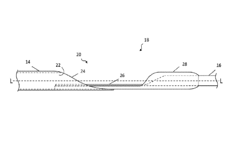
[0020] FIG. 1 is an elevation view of a dilator having a rapid exchange
port for
sheathless access of a vessel, according to one embodiment.
[0021] FIG. 2 is a side view of the rapid exchange port of the dilator of
FIG. 1,
according to one embodiment.
[0022] FIG. 3 is a top view of the rapid exchange port of the dilator of
FIG. 1, according
to one embodiment.
DETAILED DESCRIPTION
[0023] At the outset, it is to be understood that this disclosure is not
limited to
particularly exemplified materials, architectures, routines, methods or
structures as such
may vary. Thus, although a number of such options, similar or equivalent to
those described
herein, can be used in the practice or embodiments of this disclosure, the
preferred materials
and methods are described herein.
CA 03018926 2018-09-25
WO 2017/168189 PCT/IB2016/000491
[0024] It is also to be understood that the terminology used herein is for
the purpose of
describing particular embodiments of this disclosure only and is not intended
to be limiting.
[0025] The detailed description set forth below in connection with the
appended
drawings is intended as a description of exemplary embodiments of the present
disclosure
and is not intended to represent the only exemplary embodiments in which the
present
disclosure can be practiced. The term "exemplary" used throughout this
description means
"serving as an example, instance, or illustration," and should not necessarily
be construed as
preferred or advantageous over other exemplary embodiments. The detailed
description
includes specific details for the purpose of providing a thorough
understanding of the
exemplary embodiments of the specification. It will be apparent to those
skilled in the art
that the exemplary embodiments of the specification may be practiced without
these specific
details. In some instances, well known structures and devices are shown in
block diagram
form in order to avoid obscuring the novelty of the exemplary embodiments
presented
herein.
[0026] For purposes of convenience and clarity only, directional terms,
such as top,
bottom, left, right, up, down, over, above, below, beneath, rear, back, and
front, may be used
with respect to the accompanying drawings. These and similar directional terms
should not
be construed to limit the scope of the disclosure in any manner.
[0027] Unless defined otherwise, all technical and scientific terms used
herein have the
same meaning as commonly understood by one having ordinary skill in the art to
which the
disclosure pertains.
[0028] Finally, as used in this specification and the appended claims, the
singular forms
"a, "an" and "the" include plural referents unless the content clearly
dictates otherwise.
[0029] As noted above, transradial catheterization offers significant
benefits over
femoral approaches due to the potential for reduced complications. By
employing the
techniques of this disclosure, the use of a sheath may be avoided when
introducing a guide
catheter into a vessel of the patient, such as the radial artery. Since a
sheath is not required,
a correspondingly larger diameter guide catheter may be employed. For a
majority of
6
CA 03018926 2018-09-25
WO 2017/168189 PCT/IB2016/000491
coronary interventions, a 6 French guide catheter is required. While the
median radial artery
diameter ranges from 1.9 mm to 2.5 mm in different ethnic populations,
conventional use of
a 2.5 mm access (6 French sheath) is more likely to lead to above-mentioned
problems.
[0030] While sheaths were originally designed for femoral artery access,
differences in
anatomy and physiology of the arteries such as radial artery and pedal artery
may preclude
the need to employ a sheath for access. Thus, sheathless access to an artery
may be used to
carry out a given catheterization task and may minimize the entry wound
necessary, such as
by up to two French sizes. For example, entry with a guide catheter instead of
a sheath may
be accomplished with a smaller overall diameter for a respective French size,
such as 0.5
mm or smaller. In turn, this reduces the amount the artery is stretched and
expanded, and
likewise may reduce irritation, inflammation, pain and/or the chance of
iatrogenic artery
occlusion. As such, these techniques may be employed to reduce the size of
entry in any
catheterization procedure, including those for transradial, transbrachial,
transfemoral and
transpedal access as well as others.
[0031] The techniques of this disclosure permit transradial access, for
example, while
avoiding the need of using a sheath completely and is therefore a true
sheathless access that
may be used for diagnostic as well as all kinds of coronary intervention
procedures and
peripheral procedures. Notably, these techniques work in every patient with a
smaller size
puncture (hole) for the respective catheter size required. Most diagnostic and
many
interventional procedures may be performed by 1.67 mm (5 French) guide
catheter with
sheathless access, and, if required, the same access may be expanded to a
larger size, such as
a 2.00 mm (6 French) or a 2.32 mm (7 French) guide catheter. Even for such
increased
sizes, the use of a correspondingly larger sheath is avoided to reduce radial
access size in
every procedure and thereby reduce or even eliminate the limitations of radial
access, such
as spasm, pain, injury, radial occlusion, and the inability to perform complex
interventions.
Embodiments of the present disclosure may solve all the above-mentioned
problems related
to transradial catheterization.
[0032] To help illustrate aspects of this disclosure, an exemplary
embodiment of a radial
access dilator is shown schematically in FIG. 1 in an elevation view. As
shown, dilator 10
7
CA 03018926 2018-09-25
WO 2017/168189 PCT/IB2016/000491
is an elongated member having a longitudinal axis along the line L-L, with a
tapered distal
end 12 that increases to a maximal outer diameter in tubular distal member 14.
The
maximal outer diameter may be selected to closely conform to the inner
diameter of a guide
catheter to be used in a given procedure and may be substantially constant
throughout distal
member 14.
[0033] Distal member 14 is joined to a proximal member 16 at transition
region 18,
which also forms rapid exchange port 20 as described in further detail below.
Distal
member 14 has a lumen 22 extending from distal end 12 to rapid exchange port
20, and may
have an inner diameter sized to receive a suitable guide wire, such as a
0.021" (0.58 mm)
guide wire or a 0.035" (0.88 mm) guide wire for example, although other
diameters may be
employed depending on the intended use.
[0034] Proximal member 16 extends from transition region 18 to the proximal
end of
dilator 10 and may have an outer diameter that is generally constant and less
than the
maximal outer diameter of distal member 14. Tapered distal end 12 may be about
four cm
in length to provide a smooth transition with the outer diameter of the guide
wire being
used, to facilitate dilation of the skin, subcutaneous tissue and artery wall.
If desired, some
or all of dilator 10 may have a hydrophilic coating to facilitate introduction
and
advancement through the patient's vasculature as well as to reduce friction
when a guide
catheter is advanced over the dilator. In one aspect, tapered distal end 12
and proximal
member 14 may have a hydrophilic coating.
[0035] As noted above, it is desirable for dilator 10 to combine
flexibility with
pushability, characterized by having sufficient column strength to allow the
dilator to be
advanced through the patient's vasculature. Accordingly, distal member 14 may
be formed
from a polymeric material having increased flexibility while proximal member
16 may be
formed from a relatively stiffer material, and may be polymeric or metallic.
In an
illustrative embodiment, distal member 14 may be formed from nylon
(polyamide),
urethane, polypropylene, as well as polyamide co-polymers such as, for
example, polyether
block amides (PEBAX ), or the like and proximal member 16 may be a hypotube of
stainless steel, a shape memory alloy (e.g., Nitinol or other nickel titanium
alloys) or a
8
CA 03018926 2018-09-25
WO 2017/168189 PCT/IB2016/000491
relatively stiff polymer such as PolyEtherEther Ketone (PEEK). Proximal member
16 may
also be a solid rod or wire in some embodiments. Notably, the material used
for proximal
member 16, such as metallic materials, may allow dilator 10 to be stored in a
coiled
configuration without imparting a remembered shape to proximal member 16 that
would
hinder advancement of dilator 10 through the patient's vasculature.
[0036] The relative dimensions of dilator 10 may be selected based on the
distance
between the access point and the location where the procedure is to be
performed. As a
representative illustration only, distal member 14 may be in the range of
approximately 20-
30 cm, transition region 18 may be in the range of approximately 10-15 cm and
proximal
member 16 may be in the range of approximately 90-120 cm. Accordingly, the
reduced
profile of proximal member 16 represents a significant proportion of the
overall length of
dilator 10 and presents less friction with the inner diameter of a guide
catheter, facilitating
advancement of the guide catheter over dilator 10. The overall length of
dilator 10 and the
respective lengths of each member may be tailored to reach a desired location
in the
patient's vasculature. Generally, dilator 10 may extend approximately 10-20 cm
from the
proximal end of the guide catheter when preloaded for introduction into the
vessel. With
this configuration, the proximal ends of both the guide catheter and the
dilator may be
manipulated during introduction and advancement. As noted, the maximal outer
diameter of
distal member 14 may closely correspond to the inner diameter of the guide
catheter(s)
being used in the procedure. For example, for a 6 French guide catheter, the
maximal outer
diameter may be approximately 1.80 mm, with corresponding adjustment for other
sizes.
[0037] Transition region 18 forms rapid exchange port 20 as a result of a
partial overlap
of distal member 14 and proximal member 16 as schematically shown in the side
view of
FIG. 2, in which the longitudinal axis is indicated by the line L-L, and the
top view of FIG.
3. These illustrations are not to scale, but rather are intended to show the
general
relationships between the respective members. As shown, material or layers of
such
material may be removed from tubular distal member 14 at its proximal end to
form an
exposed inner angular surface 24, referenced hereafter as a "skived portion"
24 having a
partial circumference rather than the intact tube distal to skived portion 24.
Similarly,
material may be removed from proximal member 16 to form an angular, skived
portion 26.
9
CA 03018926 2018-09-25
WO 2017/168189 PCT/IB2016/000491
In embodiments in which proximal member 16 is tubular, skived portion 26 also
has a
partial circumference rather than the intact tube proximal to skived portion
26. The angles
of skived portions 24 and 26 may be in opposition to form rapid exchange port
20 that
communicates with lumen 22 of distal member 14. In one aspect, the reduced
diameter of
proximal member 16 with respect to distal member 14 causes skived portion 26
to overlap
skived portion 24 coaxially within a projected circumference of the intact
distal member 14.
Due to the amount of material removed when forming skived portions 24 and 26,
the
opening of rapid exchange port 20 occupies a substantial portion of the
projected
circumference of tubular distal member 14, allowing for easy exit of the guide
wire. In
comparison, a conventional port formed by milling an opening through a surface
of a tube
occupies less of the circumference and the user may have to bend or otherwise
manipulate
the tubing in order to cause the guide wire to exit.
[0038] Skived portion 26 of proximal member 16 partially overlaps skived
portion 24 of
distal member 14 and they may be secured together in any suitable manner. As
an
illustration, distal member 14 is secured to proximal member 16 by transition
tubing 28 in
the embodiment shown, such that the distal end of proximal member 16,
including skived
portion 26, is coaxially disposed within transition tubing 28. In turn,
transition tubing
extends coaxially within the proximal end of distal member 14. As shown,
transition tubing
28 may overlap a sufficient amount of distal member 14 so that it extends
distally past
skived portion 24 into the intact lumen 22. However, in other embodiments,
transition
tubing 28 may not extend into the lumen and may only overlap skived portion
24. Likewise,
the distal end of skived portion 26 may either extend past skived portion 24
as shown or
may terminate before the lumen becomes intact. Transition tubing 28 may be
heat welded
where it overlaps with distal member 14 and proximal member 16 to secure them
together.
In other embodiments, adhesives or mechanical bonding as well as other known
techniques
may be used as desired. Transition tubing 28 may be left intact over the
distal end of
proximal member 16 and will conform to skived portion 26 as a result of the
heat welding
process or it may be skived in a similar manner. If left intact, transition
tubing 28 may
facilitate exit of the guide wire from rapid exchange port 20 by blocking
entrance to the
lumen of proximal member 16 when a tubular member is used. Transition tubing
28 may be
formed from similar materials as described earlier for the distal and proximal
ends (but
CA 03018926 2018-09-25
WO 2017/168189 PCT/IB2016/000491
without the metallic portion). For example, nylon (polyamide), urethane,
polypropylene, as
well as polyamide co-polymers such as, for example, polyether block amides
(PEBAX ), or
a relatively stiff polymer such as PolyEtherEther Ketone (PEEK) can be used
and the actual
material is dependent on the intended parameters of the device. Since
transition tubing
interfaces with a greater amount of surface area than the overlapping skived
portions 24 and
26, a reliable and secure bond may be formed. Further, transition tubing 28
provides a
smooth change in flexibility between the relatively stiffer proximal member 16
and the more
flexible distal member 14 while reducing the tendency to kink at the junction.
In
comparison, a conventional port formed by milling an opening through a surface
of a tube
causes discontinuous transition in flexibility and column strength and may
increase the
potential for kinking at the port. Still further, since transition tubing 28
and skived portion
26 of proximal member 16 lie coaxially within the profile of the maximal outer
diameter of
distal member 14, the attachment does not cause protrusions or disturbances
that would
impede advancement of dilator 10 through the patient's vasculature. It should
be noted that
the material used for proximal member 16 should be less flexible as compared
to the
material for distal member 14. One technique to ensure that this relationship
is maintained
during a material selection process is to measure the deflection of the
proximal member 16
with a given load on a goniometer as compared to the deflection of the distal
member using
the same load on the goniometer.
[0039] Any suitable technique may be employed to use dilator 10 for
transradial
catheterization and may be extended to cover use of other sizes of guide
catheters and guide
wires for access to other vessel in a patient. As an illustration, transradial
access is achieved
by palpation or ultrasound guidance as desired. The radial artery may be
punctured using a
21-gauge needle or similar apparatus. An anterior or posterior puncture can be
performed
by either using a bare needle or an intra-catheter venous access needle,
respectively. Once
pulsatile blood flow is seen, a guide wire may be inserted in the radial
artery, following
which the needle is removed while securing the guide wire in the radial artery
lumen and
hemostasis is achieved. An appropriate guide catheter that may be selected in
view of the
procedure being performed may be pre-loaded on dilator 10, both of which may
then be
advanced over the guide wire into the radial artery. After advancing a
corresponding
distance, the guide wire will exit from rapid exchange port 20. The relatively
smooth,
11
CA 03018926 2018-09-25
WO 2017/168189 PCT/IB2016/000491
atraumatic transition between the maximal outer diameter portion 14 and the
outer diameter
of the guide catheter resulting from the close conformance of the outer
diameter of the
dilator and the inner diameter of the guide catheter facilitates the
advancement of the guide
catheter over the dilator. Once the guide catheter has been suitably advanced,
such as so
that its distal end is adjacent the junction between tapered distal end 12 and
maximal outer
diameter distal member 14, the dilator may be removed.
[0040] As will be appreciated from the above description, access to the
radial artery
using dilator 10 may be accomplished with at least a 0.5 mm smaller hole and a
smaller
intrusion into the radial artery as compared to conventional entry with a
sheath. For
example, a 6 French sheath will lead to 2.61 mm puncture in radial artery
while using radial
access dilator 10, the radial artery puncture and the maximal diameter of a
device to be
inserted in the artery may be reduced to approximately 2.00 mm. In this
manner, most or all
patients will be able to tolerate the use of a 6 French guide catheter, with
considerably less
trauma. Further, a 7 French guide catheter (outer diameter 2.3 mm) may be used
with a
greater proportion of patients, so that more complex coronary procedures and
peripheral
procedures may be performed. In other procedures, a 5 French guide catheter
may be
employed. Regardless of the size of the guide catheter, the requirement of a
smaller hole
and avoidance/reduction of expansion and/or irritation of the radial artery as
compared to
access with a sheath will reduce or eliminate, spasm, pain, inflammation and
occlusion, and
allow a successful transradial catheterization. By employing a relatively
stiff proximal
member 16, dilator 10 exhibits improved control and pushability while being
advanced
within the patient's vasculature. Further, the relatively more flexible distal
member 14
improves navigation through the tortuous anatomy and reduces trauma. Securing
distal
member 14 to proximal member 16 at transition region 18 in the manner
described
facilitates formation of rapid exchange port 20, while maintaining column
strength and
providing kink resistance.
[0041] The preceding description has been presented with reference to
presently
disclosed embodiments of the invention. Workers skilled in the art and
technology to which
this invention pertains will appreciate that alterations and changes in the
described structure
may be practiced without meaningfully departing from the principal, spirit and
scope of this
12
CA 03018926 2018-09-25
WO 2017/168189 PCT/IB2016/000491
invention. As understood by one of ordinary skill in the art, the drawings are
not necessarily
to scale. Accordingly, the foregoing description should not be read as
pertaining only to the
precise structures described and illustrated in the accompanying drawings, but
rather should
be read consistent with and as support to the following claims which are to
have their fullest
and fair scope.
13