Note: Descriptions are shown in the official language in which they were submitted.
- 1 -
STUD, AND FIBER REINFORCED POLYMERIC BUILDING PANEL INCLUDING SUCH STUD
This is a divisional of Canadian Patent Application No. 2,823,419, filed
October 11, 2011.
BACKGROUND OF THE INVENTION
This invention relates to building systems which largely replace the upright
uses of concrete,
whether ready-mix concrete or pre-fabricated concrete blocks, or other pre-
fabricated concrete products,
in construction projects. In general, the invention relates to enclosed
buildings as well as other
structures, and replaces the concrete in below-grade frost walls and
foundation walls, and in above-grade
walls. Such concrete structures are replaced, in the invention, with
structures based on fiber-reinforced
polymer materials (FRP) and the bottoms of such FRP walls may be integrated
with a concrete
footer/floor.
Certain improvements in building construction, including building panels,
walls, buildings and
appurtenances, methods of making building panels, and methods of constructing
walls, wall systems,
and buildings are taught in co-pending applications of common assignment as
follows:
Serial Number 11/901,174, filed September 13, 2007 (Publ. No. US2008/0127607
dated June 5, 2008);
Serial Number 11/901,057, filed September 13, 2007 (Publ. No. US2008/0148659
dated June 26,2008);
Serial Number 11/900,987, filed September 13, 2007 (Publ. No. U52008/0127600
dated June 5, 2008);
Serial Number 11/900,998, filed September 13,2007 (Publ. No. US2008/0127601
dated June 5, 2008);
Serial Number 11/901,059, filed September 13, 2007 (Publ. No. US2008/0127584
dated June 5, 2008);
Serial Number 11/901,173, filed September 13,2007 (Publ. No. US2008/0127604
dated June 5, 2008);
Serial Number 11/901,175, filed September 13, 2007 (Publ. No. US2008/0127602
dated June 5, 2008);
Serial Number 12/317,164, filed December 18,2008 (Publ. No. US2009/0165411
dated July 2, 2009); and
Serial Number 61/571,290 filed June 23, 2011 and Serial Number 61/573,799
filed September 12, 2011 (both
claimed as priority to Publ. No. US2012/0324815 dated December 27, 2012).
There is a need, in the construction industry, for additional improvements in
light weight
structural building panels and building systems incorporating such building
panels. For example,
generally continuous building panels of any desired length up to a maximum
length per panel, may be
selectable in length, in height, and in thickness, whereby such structural
building panels may be used in
applications where concrete is conventionally used in residential, commercial,
and industrial construction.
Such structural building panels should be strong enough to bear the primary
compressive loads and
lateral loads which are imposed on the underlying walls in a building
enclosure or other building structure.
CA 3019070 2020-03-23
- 2 -
In light of severe wind conditions, which occur periodically in some locales,
there is a need for
building systems where overlying building structure is securely anchored to an
underlying wall structure
such as a foundation, whereby attachments between the underlying foundation
and the overlying
structure assist in preventing separation of the overlying structure from the
foundation under severe wind
conditions, and where the foundation wall is securely and automatically
anchored to the footer by the
process of creating the footer.
There is also a need for walls which are generally impermeable to water,
including at joints in the
wall.
These and other needs are alleviated, or at least attenuated, by the novel
construction products,
and methods, and building systems of the invention.
SUMMARY OF THE INVENTION
This invention includes light weight fiber-reinforced polymeric (FRP)
structural building panels
and panel assemblies, sized and configured for construction of non-portable
wall structures permanently
fixed to the ground, optionally tying overlying structure to an underlying
footer through such panels and
panel assemblies. In integrated building systems of the invention, the footer
can include spaced footer
components, with main footer components extending between and about the spaced
footer components,
and the footer and a floor at the footer level may be integrated, and the
foundation wall may be part of a
unitary structure fabricated by flowing fluid concrete under segments of the
wall such that the lower
portion of the wall is embedded in the concrete, while anchors from the wall
extend into the space into
which the concrete is being flowed. Extension flanges of the foundation wall,
or mechanical fasteners
tied to the foundation wall, can be used to tie the foundation wall to the
underlying concrete, and to tie an
overlying wall or floor to the foundation wall. Fiber schedule and orientation
in the panels provide
enhanced properties of strength of a panel/wall per unit dimension relative to
mass of the panel/wall per
unit dimension and/or quality of distribution of resin within the panel. Panel
profiles as molded, and
molds to make such profiles, enhance panel fabrication.
In a first family of embodiments, the invention comprehends a method of
fabricating a structure
foundation having a first length. The method comprises preparing, as needed,
an elongate footer trench,
the footer trench having a bottom, and a second length; establishing a first
set of footer elements in the
footer trench, the first set of footer elements being spaced from each other
along the length of the footer
trench; placing wall elements on the first set of footer elements such that
the wall elements span the
spaces between respective ones of the first set of footer elements; and after
placing the wall elements on
CA 3019070 2018-09-28
- 3 -
the first set of footer elements, establishing a second set of footer elements
under the wall elements so
as to create a continuous-length footer under the wall elements, the
continuous-length footer comprising
ones of the first set of footer elements and ones of the second set of footer
elements.
In some embodiments, the invention further comprises fabricating the first set
of footer elements
in the footer trench, with elongate reinforcing material, optionally steel
reinforcing rods, extending through
and between respective ones of the first set of so-fabricated footer elements,
and the elongate reinforcing
material extending along the length of the footer trench.
In some embodiments, the establishing of the second set of footer elements
under the wall
comprising flowing fluid concrete under the wall elements and onto tops of the
first set of wall elements.
In some embodiments, the method includes locating the footer elements in the
trench such that a
footer element of the first set of footer elements is positioned under each
joint between adjacent ones of
the wall elements whereby each such wall element is supported by a footer
element of the first set of
footer elements, at each joint between wall elements.
In a second family of embodiments, the invention comprehends a footer having a
top, and being
defined along a length of a footer path, the footer comprising a plurality of
individual mini footers, spaced
from each other along the length of the footer path, a given such mini footer
having a top and a bottom,
and opposing sides extending along the length of the footer path, and a
plurality of ready-mix concrete
main footer components extending along the length of the footer path, and
extending between respective
ones of the mini footers such that the mini footers and the main footer
components collectively define a
continuous-length footer.
In some embodiments, at least one of the main footer components extends about
at least one of
the mini footers and joins an adjacent main footer component such that the
combination of the at least
one main footer component and the adjacent main footer component define a
single concrete structure.
In some embodiments, the main footer components extend about the mini footers
so as to define
an extended-length footer wherein at least a majority of the mini footers are
covered on at least one side
or top of the mini footers by the main footer components thereby directly
interfacing the respective mini
footers within the collective span of the concrete which forms the main footer
components.
In some embodiments, the main footer components extend over the tops of the
mini footers, and
about at least one side of the mini footers so as to enclose the mini footers
in the main footer
components on the tops and at least one side of the respective mini footers.
In some embodiments, the main footer components cover the mini footers on the
tops of the mini
footers and on the opposing sides of the mini footers.
CA 3019070 2018-09-28
- 4 -
In some embodiments, the footer further comprises one or more reinforcing
rods, optionally steel
reinforcing rods, extending along the length of the footer path, extending
from one such mini footer
through a main footer component and into a next-adjacent mini footer.
In some embodiments, the invention comprehends a concrete base comprising a
such two-
component footer, the mini footers are concrete mini footers, and the concrete
base comprises a
concrete slab adjacent the footer and extending away from the footer as a
structure unitary with the main
footer components.
In some embodiments, the invention comprehends a foundation comprising a such
two-
component footer, and a foundation wall, a lower portion of the foundation
wall being embedded in the
footer.
In some embodiments, the foundation wall interfaces with the top of at least
one such mini footer
and extends upwardly from such mini footer.
In some embodiments, the footer has first and second opposing sides, the main
footer
components extend over the tops of the mini footers, and extending across the
mini footers on at least
one of the sides of the footer.
In some embodiments, the foundation further comprises anchors secured to the
foundation wall
and extending into the concrete base.
In some embodiments, such anchors extend through portions of the foundation
wall below the
top of the footer.
In some embodiments, the foundation further comprises abutment structure
brackets embedded
in the mini footer and participating in at least temporarily mounting the
foundation wall to the mini footer.
In some embodiments, the mini footers are concrete mini footers, such that the
footer is a
concrete footer, having first and second opposing sides, and a width
therebetween, and a depth between
a top and a bottom of the footer, the concrete footer extending under the
foundation wall, and an adjacent
concrete slab defining a unitary concrete structure with the main footer
components, the concrete slab
having a second width at least two times as wide as the first width, and a
depth less than the depth of the
footer.
In some embodiments, the invention comprehends a building comprising one or
more such
foundations, and building superstructure overlying, and secured to, the one or
more foundations.
In a third family of embodiments, the invention comprehends a method of
fabricating a structure
foundation, the foundation having a first length. The method comprises
preparing, as needed, an
elongate footer trench, the footer trench having a bottom, and a second
length; establishing a plurality of
mini footers in the footer trench, the mini footers having tops, bottoms, and
opposing sides, and being
CA 3019070 2018-09-28
- 5 -
spaced from each other along the length of the footer trench; placing a first
set of wall segments adjacent
each other, on the tops of the mini footers, such wall segments having inner
and outer surfaces; joining
adjacent ones of the wall segments to each other and thereby creating closed
joints between respective
ones of the adjacent wall segments, thereby to define a portion of the
foundation wall, the wall portion
having opposing surfaces which extend along the length of the elongate footer
trench; placing footer
forms, having form tops, along the length of the footer trench which is
occupied by such mini footers and
such wall segments whereby the footer forms define a footer spatial volume
along the length of the footer
trench, between the bottom of the footer trench and up to the elevations of
the tops of the footer forms,
the mini footers being disposed in the so-defined footer spatial volume, the
tops of the mini footers, and
correspondingly, the bottoms of the wall segments, being below the elevations
of the tops of the footer
forms; and with the wall segments on the tops of the mini footers, finishing
fabrication of a footer along
the length of the footer trench by placing fluid concrete into the footer
trench, including flowing the fluid
concrete under the wall segments and onto the tops of the mini footers, so as
to create main footer
components, interfacing with the mini footers and connected to each other
about the mini footers so as to
create a continuous-length footer comprising the mini footers and the main
footer components, the main
footer components having top surfaces which overlie the tops of the mini
footers and which define a top
surface of the footer, the tops of the mini footers, which support the wall
segments, thus being embedded
in the main footer components, bottom portions of the wall segments extending
below the top surface of
the concrete footer to the tops of the respective mini footers, and continuing
below the top surface of the
concrete footer between adjacent ones of the mini footers whereby bottom
portions of the wall segments
are embedded in the concrete footer for substantially the full lengths of the
wall segments.
In some embodiments, the method includes positioning a such mini footer at the
location of each
such joint between wall segments such that each wall segment is supported by a
mini footer at each such
joint.
In some embodiments, the wall segments comprise a first set of wall segments,
the footer trench
comprises a first footer trench, further comprising defining a second footer
trench extending at
substantially a right angle to the first footer trench, positioning ones of
the mini footers in the second
footer trench, positioning a second set of wall segments on ones of the mini
footers in the second footer
trench, and placing concrete into the second footer trench as an extension of
the concrete in the first
footer trench, thus to define, in the second footer trench, a unitary part of
the footer structure which is
defined by the placing of the concrete, at least one of the second set of wall
segments abutting and
thereby supporting at least one of the first set of wall segments whereby the
at least one of the second
CA 3019070 2018-09-28
- 6 -
set of wall segments operates as a shear wall providing lateral support to the
abutted first set of wall
segments.
In some embodiments, the method further comprises, prior to, optionally
concurrently with,
placing the fluid concrete in the footer trench, mounting a plurality of
anchors to respective ones of the
.. wall segments such that the anchors extend, optionally laterally, from the
upstanding portions of the wall
segments into the footer spatial volume, such that the fluid concrete flows
around at least portions of the
anchors thus anchoring the respective wall segments to the concrete footer as
the fluid concrete sets
up/hardens.
In some embodiments, the method includes setting an outer footer form
outwardly of the outer
surface of at least one such wall segment, the outer footer form having a top
at a higher elevation than
the tops of adjacent ones of the mini footers, and flowing the fluid concrete
under the wall segments to
the outer footer form and upwardly above the bottoms of the respective wall
segments to approximately
the top of the respective outer footer form.
In a fourth family of embodiments, the invention comprehends a wall structure,
comprising a
footer; a wall extending upwardly from the footer, the wall having a length
and a bottom; a concrete
structure adjacent the bottom of the wall; and a plurality of anchors
extending from the concrete structure
into the wall and back into the concrete structure.
In some embodiments, the wall comprises a plurality of uprightly-oriented
studs spaced along the
length of the wall, and further comprises ones of the anchors extending from
the concrete structure,
.. through ones of the studs, and extending, from the studs, back into the
concrete structure.
In some embodiments, the anchors extend from the concrete structure into an
upright element of
the wall structure and back into the concrete structure.
In some embodiments, the wall structure has an inner surface and an outer
surface, and studs
extending inwardly, away from the inner surface, the anchors extending from
the concrete structure into
ones of the studs and back into the concrete structure.
In some embodiments, the footer comprises a concrete footer having first and
second opposing
sides and a first width therebetween, and a depth between the top and the
bottom of the concrete footer,
the concrete footer extending under the foundation wall, an adjacent concrete
slab defining a unitary
concrete structure with the main footer components, the concrete slab having a
second width at least 2
times as wide as the first width, and a depth less than the depth of the
footer.
In a fifth family of embodiments, the invention comprehends a wall structure,
comprising a footer;
a wall extending upwardly from the footer, the wall having a length and a
bottom; a concrete structure
CA 3019070 2018-09-28
- 7 -
adjacent the bottom of the wall; and a plurality of anchors extending from the
wall into the concrete
structure and thereby anchoring the wall to the concrete structure.
In some embodiments, the anchors extend from an upright element of the wall
structure into the
concrete structure.
In some embodiments, the wall structure has an inner surface and an outer
surface, the wall
structure comprising a plurality of uprightly-oriented studs spaced along the
length of the wall, and
extending inwardly, away from the inner surface, the anchors extending from
ones of the studs into the
concrete structure.
In some embodiments, the anchors extend from said wall structure, optionally
from the studs,
into the concrete structure at angles of about 20 degrees to about 70 degrees
from vertical.
In some embodiments, the anchors extend laterally into the concrete structure.
In a sixth family of embodiments, the invention comprehends a fiber-reinforced
polymeric load-
bearing building panel assembly. The building panel assembly comprises a
building panel, having a top
and a bottom, and a length, the building panel comprising an outer fiber-
reinforced polymeric layer, an
inner fiber-reinforced polymeric layer, opposing the outer layer and spaced
from the outer layer, and a
space between the inner layer and the outer layer, the space being occupied by
thermally insulating
foam; and a plurality of elongate studs spaced from each other along the
length of the building panel, and
mounted to the inner layer and extending away from the inner layer and away
from the outer layer, a
given stud having a stud top end adjacent the top of the building panel and
extending to a stud bottom
end adjacent the bottom of the building panel, the stud comprising an end
panel remote from the inner
layer, and at least one leg extending from the end panel to an inner panel of
the stud proximate, and
mounted to, the inner layer of the building panel, and at least one flange
extending from at least one of
the top or the bottom of the stud.
In some embodiments, the at least one flange is located at the bottom of the
building panel and
mounts the stud to a bottom plate of the building panel assembly.
In some embodiments, the invention comprehends a foundation comprising a
footer, and one or
more of the building panel assemblies extending into the footer, and upwardly
therefrom, the at least one
flange on a respective stud extends from the bottom of the respective stud and
away from the stud into
the footer.
In some embodiments, the at least one flange is located at the top of the
building panel and
extends upwardly from the end panel, as a substantially straight-line
extension of the end panel.
CA 3019070 2018-09-28
- 8 -
In some embodiments, the at least one flange extends from the top of a
respective stud and is
bendable at a sharp angle to at least about 90 degrees from the top-to-bottom
direction of extension of
the respective stud.
In some embodiments, the at least one flange is secured to the overlying
building structure,
thereby securing the overlying building structure to the upright wall.
In some embodiments, at least one mechanical fastener extends through the at
least one flange
and into an element of the overlying building structure, such as into
overlying upright wall structure of into
overlying floor structure, thereby securing the overlying building structure
to the upright wall.
In a seventh family of embodiments, the invention comprehends a fiber-
reinforced polymeric
load-bearing building panel assembly. The building panel assembly comprises a
building panel, having a
top and a bottom, the building panel comprising an outer fiber-reinforced
polymeric layer, an inner fiber-
reinforced polymeric layer, opposing the outer layer and spaced from the outer
layer, and a plurality of
load-bearing studs defining channels therebetween; and an upper attachment
bracket at the top of the
building panel, secured to the building panel between adjacent ones of the
studs, and having a first
bracket panel aligned with the top of the building panel.
In some embodiments, the building panel assembly further comprises a lower
attachment
bracket at the bottom of the building panel, secured to the building panel
between adjacent ones of the
studs, and having a second bracket panel aligned with the bottom of the
building panel.
In some embodiments, the invention comprehends a constructed structure
comprising a footer, a
such load-bearing building panel assembly, and a floor and/or wall structure
overlying the load-bearing
building panel assembly and interfacing with the first bracket panel, the
second bracket panel being
secured to the footer, at least one mechanical fastener extending through the
upper attachment bracket
in the respective channel and into at least one of the overlying floor and/or
wall structure, thereby
providing direct attachment of the overlying floor and/or wall structure to
the footer through the building
panel assembly.
In an eighth family of embodiments, the invention comprehends a method of
securing overlying
floor and/or wall structure of a building to an underlying wall of such
building, the underlying wall having a
length, a top, and a bottom. The method comprises emplacing an underlying such
wall having a top and
a bottom, the underlying wall comprising an outer fiber-reinforced polymeric
layer, an inner fiber-
reinforced polymeric layer, opposing the outer layer and spaced from the outer
layer, a plurality of load-
bearing studs defining channels therebetween, a plurality of channels
extending, from the inner layer,
inwardly into such building between respective ones of the studs, and upper
attachment brackets at the
top of the wall, secured to the wall and in respective ones of the channels, a
given upper attachment
CA 3019070 2018-09-28
- 9 -
bracket having a first bracket panel extending perpendicular to the inner
layer and aligned with the top of
the building panel; positioning overlying floor and/or wall structure, not
part of the underlying wall, above
the underlying wall; and driving mechanical fasteners, spaced along the length
of the underlying wall,
through the first bracket panels and into the overlying floor and/or wall
structure, and thereby securing the
overlying floor and/or wall structure to the underlying wall.
In some embodiments, the method further comprises securing the overlying floor
and/or wall
structure to an underlying wall of such building, and further comprises
providing lower attachment
brackets in respective ones of the channels at the bottom of the wall, and
securing a given such lower
attachment bracket, having a second bracket panel aligned with the bottom of
the building panel, to both
the underlying wall and the footer.
In a ninth family of embodiments, the invention comprehends a fiber-reinforced
polymeric load-
bearing building panel, comprising an outer fiber-reinforced polymeric layer
about 0.10 inch thick to about
0.15 inch thick; an opposing inner fiber-reinforced polymeric layer about 0.10
inch thick to about 0.15 inch
thick; and a plurality of load-bearing studs, extending along the height of
said building panel when said
building panel is in such upright orientation, the studs having walls,
defining outer surfaces of the studs,
about 0.10 inch thick to about 0.15 inch thick, the building panel having a
height defined between a top
and a bottom of the building panel when the building panel is in an upright
orientation, a length, and a
thickness between the inner layer and the outer layer, excluding any
dimensions of the studs, of about 2
inches to about 5 inches, the building panel having a mass of no more than 80
pounds per linear foot
length of the building panel, and at least one of vertical crush resistance of
at least 4000 pounds per
linear foot length of the building panel when a load is evenly distributed
over the length and the thickness
of the building panel, and a horizontal load bending resistance capacity of no
more than U120, optionally
no more than 11180, optionally no more than L/240.
In a tenth family of embodiments, the invention comprehends a fiber-reinforced
polymeric load-
bearing building panel, comprising an outer fiber-reinforced polymeric layer
comprising a first set of fibers
in a first cured resin, the outer layer defining a first outermost surface of
the building panel when the
building panel is disposed in an upstanding orientation; an inner fiber-
reinforced polymeric layer
comprising a second set of fibers in a second cured resin, the inner layer
being spaced from the outer
layer and defining a second outermost surface of the building panel when the
building panel is disposed
in such upright orientation; a plurality of fiber-reinforced polymeric load-
bearing studs comprising a third
set of fibers in a third cured resin, the studs being spaced along the length
of the building panel and
extending away from the building panel, including away from the second
outermost surface; and at least
about 60 percent by weight, optionally at least about 70 percent by weight, of
at least one of the first,
CA 3019070 2018-09-28
- 10 -
second, and third sets of fibers, collectively, extending in a direction
within 15 degrees of vertical when
the building panel is in a vertical orientation and the studs are in a
vertical orientation.
In an eleventh family of embodiments, the invention comprehends a fiber-
reinforced polymeric
building panel. The building panel has a top and a bottom, defined when the
building panel is in an
upright orientation, a height between the top and the bottom, a length, and a
thickness, the building panel
comprising an outer fiber-reinforced polymeric layer, the outer layer defining
a first outermost surface of
the building panel; an inner fiber-reinforced polymeric layer, the inner layer
generally defining a second
outermost surface of the building panel; polymeric foam in a space between the
inner layer and the outer
layer and extending from the top of the building panel to the bottom of the
building panel; and a plurality
.. of studs extending from the second outermost layer, away from the first
outermost layer, to stud end
panels at distal ends of the studs, at least one of the top and the bottom of
the building panel defining a
draft angle extending, from the inner layer, across a such stud to at least
proximate the distal end panel
of the stud, the draft angle being based on a base line perpendicular to the
outer layer.
In some embodiments, the draft angle is initiated at the outer layer, extends
to the inner layer,
and extends from the inner layer and across the respective stud to the end
panel of the stud.
In some embodiments, the draft angle comprises a first draft angle extending
across the studs
and a second draft angle extending between the inner and outer layers, the
first draft angle being greater
than second draft angle.
In some embodiments, the building panel comprises a molded unit, fabricated in
a mold, the
other of the top and bottom, as molded, defining an angle perpendicular to the
outer surface of the outer
layer.
In some embodiments, magnitude of the first draft angle is about 1 degree to
about 25 degrees
and magnitude of the second draft angle is about 0.25 degree to about 15
degrees.
In a twelfth family of embodiments, the invention comprehends a method of
fabricating a finished
fiber-reinforced polymeric building panel having a top and a bottom, defined
when the building panel is in
an upright orientation, the building panel further having a height between the
top and the bottom, a
length, and a thickness, the building panel comprising an outer fiber-
reinforced polymeric layer, the outer
layer defining a first outermost surface of the building panel, an inner fiber-
reinforced polymeric layer, the
inner layer generally defining a second outermost surface of the building
panel, polymeric foam in a
space between the inner layer and the outer layer, and a plurality of studs
extending from the second
outermost layer, away from the first outermost layer, to stud end panels at
distal ends of the studs The
method comprises loading precursors of the studs, the inner layer, the outer
layer, and the polymeric
CA 3019070 2018-09-28
- 11 -
foam into a mold having a non-perpendicular draft angle at an end of the mold
corresponding to one of
the top and the bottom of the building panel; closing the mold, and adding any
remaining ingredients
needed for molding the building panel, and molding the building panel; opening
the mold and removing
the molded panel, the molded panel having a top end, a bottom end, and
opposing sides, the draft angle
on at least one of the top and bottom ends of the molded panel corresponding
to the non-perpendicular
draft angle at the respective end of the mold; and cutting the top and/or
bottom end off the panel to obtain
the desired finished panel having desired angle(s) at the top and the bottom
of the panel.
In some embodiments, the method comprises cutting off both the top and the
bottom of the panel
after removing the panel from the mold.
In some embodiments, the respective mold end has a first non-perpendicular
angle which
extends across, and forms, the tops of the studs, and a second different non-
perpendicular angle which
extends across, and forms the top of the panel between the inner and outer
layers.
In an thirteenth family of embodiments, the invention comprehends a mold
adapted to receive
resin, and solid precursor components of a fiber-reinforced polymeric building
panel to be fabricated by
molding, and to fabricate such fiber-reinforced polymeric building panel, such
building panel having a top
and a bottom, defined when the building panel is in an upright orientation,
such building panel further
comprising an outer fiber-reinforced polymeric layer defining a first
outermost surface of such building
panel, an inner fiber-reinforced polymeric layer defining an opposing second
outermost surface of such
building panel, polymeric foam in a space between such inner layer and such
outer layer and extending
from the top of such building panel to the bottom of such building panel, and
a plurality of studs extending
from the second outermost layer, away from the first outermost layer, to
distal ends of such studs, at
least one of the top and the bottom of such building panel having a draft
angle extending across such
studs to end panels of such studs, the draft angle being based on a base line
perpendicular to such outer
layer, the mold comprising a first mold member defining a cavity configured to
receive precursor
elements, including precursor elements of such studs, of such building panel
to be molded, the first mold
member having a first end corresponding to the top of such building panel when
molded, and an
opposing second end corresponding to the bottom of such building panel when
molded; and a second
mold member adapted to cooperate with the first mold member, with such
precursor elements of such
building panel between the first and second mold members, thereby to close the
mold for mold-
fabrication of such building panel, the second mold member having an inner
surface which defines a
location of such first outermost surface of such building panel when such
building panel is molded, at
least one of the first and second ends of the first mold member defining a
draft angle thereof initiated at
locations corresponding, on the respective end of the mold member, to an end
of such studs of such
CA 3019070 2018-09-28
- 12 -
building panel as molded, and extending across locations of the respective end
of the first mold member
which correspond to ends of such studs as molded, the draft angle being based
on a base line
perpendicular to the inner surface of the second mold member and extending
toward the other of the first
and second ends of the first mold member.
In some embodiments, the draft angle further extends across locations of the
respective end of
the first mold member which correspond to ends of such inner layer, such outer
layer, and such foam as
molded.
In some embodiments, the mold further comprises a vacuum port adapted to
withdraw gas from
inside the mold when the mold is closed and sealed, and a resin port adapted
for receiving resin into the
mold as gas is being withdrawn through the vacuum port.
In some embodiments, the other of the first and second ends of the first mold
member extends at
an angle perpendicular to the inner surface of the second mold member.
In some embodiments, the draft angle comprises a first draft angle of the
respective end of the
mold, initiated at locations corresponding to end panels of such studs of such
building panel as molded,
and extending to locations corresponding to approximately an end of such inner
layer of such building
panel as molded, and the mold further comprises a second draft angle at the
same end of the mold,
extending from locations corresponding to such end of such inner layer of such
building panel as molded
and across locations corresponding to an end of such foam to an end of such
outer layer as molded, the
first and second draft angles being based on the base line perpendicular to
the inner surface of the
second mold member, the first draft angle being greater than the second draft
angle.
In some embodiments, the magnitude of the first draft angle is about 1 degree
to about 25
degrees and magnitude of the second draft angle is about 0.25 degree to about
15 degrees.
In a fourteenth family of embodiments, the invention comprehends a fiber-
reinforced polymeric
load-bearing building panel, having a height defined between a top and a
bottom of the building panel
when the building panel is in an.upright orientation, a length, and a
thickness between first and second
opposing extremities of the building panel. The building panel comprises an
outer fiber-reinforced
polymeric layer; an opposing inner fiber-reinforced polymeric layer; and a
plurality of load-bearing studs,
extending upwardly when the building panel is in such upright orientation, the
building panel having a
mass of no more than 80 pounds per linear foot and having a ratio of vertical
crush load capacity of the
building panel to mass of the building panel, per linear foot of at least
about 125/1.
In a fifteenth family of embodiments, the invention comprehends a fiber-
reinforced polymeric
load-bearing building panel, the building panel having a height defined
between a top and a bottom of the
building panel when the building panel is in an upright orientation, a length,
and a thickness, the load-
CA 3019070 2018-09-28
- 13 -
bearing building panel comprising an outer fiber-reinforced polymeric layer,
the outer layer defining an
outwardly-facing surface of the building panel when the building panel is
being used as a load-bearing
part of a load-bearing wall of a building; an inner fiber-reinforced polymeric
layer, the inner layer generally
defining an inwardly-facing surface of the building panel when the building
panel is being used as such
load-bearing part of such load-bearing wall of such building; a plurality of
foam blocks extending
generally from the inner layer to the outer layer and from the top of the
building panel to the bottom of the
building panel, a given foam block having an outer surface disposed toward the
outer layer, an inner
surface disposed toward the inner layer, and opposing side surfaces; and at
least one fibrous layer
extending across, and covering, the outer surface, and across and covering,
the opposing side surfaces,
of the given foam block, and extending, from the side surfaces, onto and part
way across the inner
surface of the given foam block, and thereby defining a substantial distance
between opposing ends of
the at least one fibrous layer at the inner surface of the given foam block,
the fibrous layer being secured
to the inner surface of the given foam block at or adjacent the respective
ends of the fibrous layer.
In some embodiments, the at least one fibrous layer comprises a first
structural sub-layer, and a
flow-control layer between the first structural sub-layer and the outer
surface of the given foam block.
In some embodiments, the fibrous layer is secured to the given foam block by
fasteners which
are driven through both the structural sub-layer and the flow-control sub-
layer, and are further driven into
the given foam block.
In some embodiments, at least about 70 percent by weight of the fiber in the
first structural sub-
layer extends continuously along a path in a direction progressing between the
top and the bottom of the
building panel.
In some embodiments, at least about 60 percent by weight of fiber in the first
structural sub-layer
traverses a path between the top and the bottom of the building panel, along
an angle of no more than 15
degrees from a vertical path through the building panel when the building
panel is in an upright
orientation.
In a sixteenth family of embodiments, the invention comprehends a fiber-
reinforced polymeric
load-bearing building panel, the building panel comprising an outer fiber-
reinforced polymeric layer,
defining an outwardly-facing surface of the panel when the panel is being used
as a load-bearing part of
a load-bearing wall of a building; an inner fiber-reinforced polymeric layer,
generally defining an inwardly-
facing surface of the panel when the panel is being used as such load-bearing
part of such load-bearing
wall of such building; one or more blocks of foam material between the inner
and outer layers; a plurality
of fiber-reinforced studs interfacing with the inner layer and spaced along
the length of the building panel
and extending away from the outer layer, a given stud comprising a stud
substrate having a distal end
CA 3019070 2018-09-28
- 14 -
remote from the foam blocks and a proximal end adjacent the foam blocks, and
first and second sides
extending between the distal end and the proximal end; and at least one
fibrous layer extending across
the distal end of the given stud substrate, and extending across the sides of
the given stud substrate, and
terminating proximate the proximal end of the stud substrate, the at least one
fibrous layer being secured
to the stud substrate at or adjacent the proximal end of the given stud
substrate.
In some embodiments, the at least one fibrous layer is secured to the stud
substrate at or
adjacent the proximal end of the given stud substrate, by mechanical fasteners
which extend through the
at least one fibrous layer and into the stud substrate.
In a seventeenth family of embodiments the invention comprehends a fiber
reinforced polymeric
building panel, the panel comprising an outer fiber-reinforced polymeric
layer, defining an outwardly-
facing surface of the building panel when the building panel is being used as
a load-bearing part of a
load-bearing wall of a building; an inner fiber-reinforced polymeric layer,
generally defining an inwardly-
facing surface of the building panel when the building panel is being used as
such load-bearing part of
such load-bearing wall of such building; one or more blocks of foam material
between the inner and outer
layers, the one or more blocks of foam material spacing the inner and outer
layers from each other, at
least one of the inner and outer layers being defined at least in part by a
first sub-layer wherein at least
about 70 percent by weight of fiber in the first sub-layer extends along paths
continuously progressing
between the top and the bottom of an uprightly-oriented such building panel, a
second sub-layer
disposed between the first sub-layer and the one or more blocks of foam
material, and a third sub-layer
disposed outwardly, in the building panel, of the first sub-layer, wherein the
first sub-layer comprises at
least five times as much fiber by weight as either of said second or third sub-
layers, and wherein fibers of
the second and third sub-layers extend along paths progressing other than
continuously between the top
and the bottom of the building panel such that, prior to fluid resin being
cured as part of the process of
fabricating the building panel, liquid resin flows preferentially along and
through the second and third sub-
layers as compared to flow of such liquid resin along and through the first
sub-layer.
In some embodiments, the first sub-layers in said inner and outer layers
comprise about 45-
ounces per square yard to about 55-ounces per square yard unidirectional fiber
extending continuously
along a path between the top and the bottom of the building panel and wherein
at least one of the second
and third sub-layers comprises about 1-ounce per square yard to about 10-
ounces per square yard of
fiber, either oriented transversely to the unidirectional fiber in the first
layer or extending in random
directions within the confines of the respective sub-layer.
In some embodiments, the building panel further comprises a plurality of fiber-
reinforced
polymeric studs on an inner side of the building panel in combination with the
inner layer, the studs being
CA 3019070 2018-09-28
- 15 -
spaced along the length of the building panel and extending away from the
outer layer, a given stud
comprising a stud substrate proximate the at least one foam block and having a
distal end remote from
the at least one foam block and a proximal end adjacent the at least one foam
block, and first and second
stud substrate sides extending between the distal end and the proximal end of
the respective stud, the
.. first and second sub-layers of the inner layer extending about the studs,
and a stud wrap layer extending
across the distal end of a given stud and extending between the distal end and
the proximal end, and
terminating proximate the proximal ends of the stud substrate side walls, the
stud wrap layer comprising
a fourth sub-layer wherein at least about 60 percent by weight, optionally at
least about 70
percent by weight, of fiber in the fourth sub-layer extends along paths
continuously progressing between
.. the top and the bottom of an uprightly-oriented building panel, and a fifth
sub-layer disposed between the
fourth sub-layer and the first sub-layer of the inner layer, wherein the
fourth sub-layer comprises at least
5 times as much fiber by weight as the fifth sub-layer, and wherein the fifth
sub-layer extends along paths
progressing other than continuously between the top and the bottom of the
building panel such that, prior
to fluid resin being cured as part of fabricating the building panel, liquid
resin flows preferentially along
and through the fifth sub-layer as compared to flow of such liquid resin along
and through the fourth sub-
layer.
More specifically, there is provided in accordance with one aspect of the
invention, a fiber-
reinforced polymeric load-bearing building panel, the building panel
comprising:
(a) a fiber-reinforced polymeric building panel main body, having a top
and a bottom, first and
second opposing ends, and a length between the opposing ends, the main body,
comprising
(I) an outer fiber-reinforced polymeric layer,
(ii) an inner fiber-reinforced polymeric layer, opposing the outer layer
and spaced from the
outer layer, and
(iii) a space between the inner layer and the outer layer, the space being
occupied by
thermally insulating foam; and
(b) a plurality of elongate fiber-reinforced polymeric studs spaced from
each other along the length
of the main body and extending away from the inner layer and away from the
outer layer,
at least one of the studs having a stud top end adjacent the top of the
building panel and a stud bottom
end adjacent the bottom of the building panel, the at least one of the studs
comprising an end panel
.. remote from the inner layer, and at least one leg extending from the end
panel to an inner panel of the
stud, a combination of the end panel, the inner panel, and the leg,
collectively, comprising a stud profile,
CA 3019070 2021-10-08
- 15a -
at least one flange comprising an extension of a first portion of the stud
profile beyond what is
otherwise the top end or the bottom end of the at least one of the studs
extending from at least one of the
top or the bottom of the at least one of the studs.
In one embodiment thereof, the flange comprises an extension of less than all
of the stud profile,
while in other embodiments thereof, the flange comprises an extension of a
respective one of the end
panel, the inner panel, or the leg beyond what is otherwise the top end or the
bottom end of the at least
one of the studs.
In some embodiments thereof, the flange is integral with at least one of the
end panel, the inner
panel, or the at least one leg.
In accordance with another aspect of the invention, there is provided an
elongate fiber-reinforced
polymeric stud, for use as an element of an upstanding building panel, the
elongate fiber-reinforced
polymeric stud, in an upstanding orientation, having a top end and a bottom
end, and a length between
the top end and the bottom end, the elongate fiber-reinforced polymeric stud
comprising an end panel
having first and second opposing edges, and first and second legs extending
from the opposing edges of
the end panel and extending generally parallel to each other, a combination of
the end panel and the first
and second legs, collectively, comprising a stud profile, at least one flange
comprising an extension of a
first portion of the stud profile beyond what is otherwise the top end or the
bottom end of the stud
extending from one of the top or the bottom of at least one of the end panel
or one of the legs, as a
unitary extension of the respective the end panel or leg.
In one embodiment thereof, the flange comprises an extension of less than all
of the stud profile,
while in other embodiments thereof, the flange comprises an extension of a
respective one of the end
panel, the inner panel, or the leg beyond what is otherwise the top end or the
bottom end of the at least
one of the studs.
BRIEF DESCRIPTION OF THE DRAWINGS
FIGURE 1 shows a representative pictorial view, with parts removed, of a
building foundation
wall fabricated using elements, and building system structures, of the
invention.
FIGURE 2 is a fragmented interior view of a section of one of the upstanding
wall structures
shown in FIGURE 1.
FIGURE 3 is an elevation-view cross-section of the upstanding wall structure
taken at 3-3 of
FIGURE 1.
FIGURE 4 is an outside elevation representation of the upstanding wall
structure of FIGURE 3.
CA 3019070 2021-10-08
- 15b -
FIGURE 5 is a plan-view cross-section of a portion of a foundation wall of the
invention.
FIGURE 6 is an enlarged plan-view cross-section of a portion of the foundation
wall structure of
FIGURE 5.
FIGURE 7 is an elevation view cross-section of the foundation wall structure
illustrated in
FIGURES 5 and 6.
CA 3019070 2021-10-08
- 16 -
FIGURE 7A shows an enlarged elevation view of a top portion of a wall section
illustrating a
resin-fiber composite top cap, and a top plate, collectively being used in
anchoring the overlying building
structure to the underlying wall structure at the top of the underlying wall.
FIGURE 7B shows an enlarged elevation view cross-section as in FIGURE 7,
illustrating an
anchor bracket, and a top plate, collectively being used in anchoring the
overlying building structure to
the underlying wall structure.
FIGURE 70 shows an enlarged elevation view as in FIGURE 7A, illustrating an
alternative
embodiment of the top cap.
FIGURE 8is a pictorial line rendering of a resin-fiber composite support
bracket, which may be
mounted to the top of a foundation wall of the invention, and used for
positioning other building structure
relative to the wall.
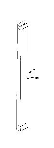
FIGURE 9 is a pictorial line rendering of a channel stud which can be
incorporated into a building
panel of the invention as illustrated in e.g. FIGURES 5-7.
FIGURES 10A and 10B are pictorial line renderings of second and third
embodiments of studs
which can be incorporated into building panels of the invention.
FIGURE 11 is a pictorial line rendering of a resin-fiber composite "H"
connector which is used to
connect first and second building panels/wall sections to each other along a
straight path.
FIGURES 12 and 13 are pictorial line renderings of resin-fiber composite angle
brackets which
can be used on inner and/or outer surfaces of a wall section, connecting first
and second wall sections to
each other at selected angles.
FIGURES 14 and 14A are pictorial views of exemplary right-angle plate anchor
brackets useful
at the tops and bottoms of building panels of the invention e.g. for securing
the panels to underlying
structure and securing overlying and/or weight-bearing or weight-transferring
structures to the building
panel.
FIGURE 15 shows a plan view cross-section of an embodiment of building panels
of the
invention wherein channel studs are between the inner layer and foam blocks.
FIGURE 16 shows a plan view cross-section of a wall section using studs which
extend to the
outer layer.
FIGURE 17 shows a plan view cross-section of an upstanding building panel
where foam blocks,
between the inner and outer layers, are wrapped in layers of fiber.
FIGURE 18 shows a cross-section as in FIGURE 17, illustrating a ribbed outer
layer.
CA 3019070 2018-09-28
- 17 -
FIGURE 19 illustrates a fragmentary end elevation view of a building panel pre-
form in a vacuum
bag molding process being used to fabricate a building panel with foam blocks,
wrapped in fiber as in
FIGURE 17, and an inner layer overlying the studs as illustrated in FIGURE 15.
FIGURE 20 shows a plan view cross-section of another embodiment of an
upstanding building
panel of the invention wherein fiber layers, wrapped about foam blocks,
provide the reinforcement
structure of the reinforcing members as well as stud reinforcement.
FIGURE 21 shows a plan view cross-section of another embodiment of upstanding
building
panels.
FIGURE 22 shows a cross-section of a building panel incorporating rectangular
studs as in
FIGURE 10B.
FIGURE 23 illustrates, in line representation, vacuum infusion apparatus for
making a building
panel of the invention, which building panel has studs extending from the
inner surface thereof.
FIGURE 24 shows a cross-section of a building panel incorporating fiber-
wrapped foam blocks
as studs.
FIGURE 25 shows an end view of a top portion of the panel of FIGURE 24.
FIGURE 26 shows a cross-section of a building panel wherein fiber-wrapped foam
blocks are
disposed between the inner and outer layers, wherein the second outermost
layer overlies the studs,
wherein reinforcement layers are added over the otherwise first and second
outermost layers.
FIGURE 27 shows a cross-section of a building panel of the invention having no
intercostals, a
first reinforcement layer over the otherwise first outermost layer, a second
reinforcement layer between
the foam panel and the second outermost layer, and the second outermost layer
overlying the studs and
the second reinforcement layer.
FIGURE 28 shows an enlarged plan-view cross-section of a portion of another
embodiment of
wall structure of the invention.
FIGURE 29 is a further enlarged cross-section view of a portion of the wall
structure of FIGURE
28, showing additional detail.
FIGURE 3,0 shows a plan view of a foam-filled panel having studs but no
reinforcing intercostals.
FIGURE 31 is an elevation view cross-section of a foundation wall structure of
the invention
showing a hollow concrete block as a mini footer.
FIGURE 32 is an elevation view as in FIGURE 31, showing a solid poured
concrete mini footer,
with steel reinforcing rods extending through the mini footer.
FIGUER 33 is a side elevation view of a lower portion of the foundation wall
of FIGURE 32, with
the top of the floor/footer shown in dashed outline.
CA 3019070 2018-09-28
- 18 -
FIGURE 34 is a top view of a straight portion of a wall structure,
illustrating use of a mini footer at
a joint in the wall.
FIGURE 35 is a top view of a corner portion of a wall structure, illustrating
use of a mini footer in
a corner wall structure.
FIGURE 36 is a top view of a straight wall section, intersected by an abutting
wall.
FIGURES 37 and 38 illustrate studs which include top and bottom mounting
flanges.
FIGURE 39 shows a fragmented elevation view cross-section of a wall structure
showing
securement of the flanged studs to underlying and overlying structure.
FIGURES 40 and 41 illustrate an FRP brace cap which extends the length of the
lower sill of a
window rough opening, thus adapting the wall to receive the side load of
backfill which can extend up to
near the lower sill of the window.
FIGURE 42 shows one or more dimension lumber studs laid flat under the window
opening to
stiffen the lower sill.
FIGURE 43 is a pictorial view showing multiple mini footers in place, along
with reinforcing steel
in the mini footers, at locations which will be occupied by the monolithic
footer/floor slab combination later
in the construction project.
FIGURE 44 shows a pictorial view of part of the footer location shown in
FIGURE 43, with a
building panel placed on one of the mini footers.
The invention is not limited in its application to the details of
construction, or to the arrangement
of the components set forth in the following description or illustrated in the
drawings. The invention is
capable of other embodiments or of being practiced or carried out in various
other ways. Also, it is to be
understood that the terminology and phraseology employed herein is for purpose
of description and
illustration and should not be regarded as limiting. Like reference numerals
are used to indicate like
components.
DETAILED DESCRIPTION OF THE ILLUSTRATED EMBODIMENTS
Referring to FIGURE 1, a plurality of interior and exterior foundation walls
10 collectively defines
the foundation 12 of a building. Each foundation wall 10 is defined by one or
more foundation building
panels 14. In the illustration, a foundation building panel 14 is shown to
include a bottom plate 16, and
further includes an upstanding wall section 18, and a top plate 20. Each
upstanding wall section 18
includes a main-run wall section 22, and uprightly-oriented reinforcing studs
23 affixed to, or integral with,
the main-run wall section, the studs being regularly spaced along the length
of the wall section, and
CA 3019070 2018-09-28
- 19 -
extending inwardly of the inner surface of the main run wall section. In the
embodiment illustrated in
FIGURE 1, anchoring brackets 24 are mounted to the studs at the tops and
bottoms of the wall section,
thus to assist in anchoring the bottom plate and the top plate, and/or any
other attachment, to the wall.
As illustrated in FIGURE 1, conventional e.g. steel I-beams 26 can be mounted
to the wall
sections, as needed, to support spans of overlying floors. Such steel I-beam
can be supported at one or
more locations along the span of the I-beam, as needed, by support posts 28
and rigid footer pads 30,
which may be embedded in a concrete slab floor 38.
Referring now to FIGURES 3, 5, and 6, the main run wall section 22 of the
building panel is
generally defined between the inner surface 25 and the outer surface 56 of the
building panel, without
considering that portion of the thickness of the wall which is defined by stud
23. The main run wall
section of the panel thus generally includes a foam core 32, an inner
fiberglass layer 34 and an outer
fiberglass layer 36. The fiberglass layers 34, 36 are fiberglass-reinforced
polymer (FRP), also known as
polymer-impregnated fiberglass. Outer layer 36 represents a first outermost
layer of the building panel.
Inner layer 34 represents a second opposing outermost layer of the building
panel. The foam core can
be foamed-in-place thermally insulating material between pre-fabricated inner
and outer layers, or can be
made from pre-fabricated blocks of thermally insulating foam material. The
foam blocks are assembled
with the remaining elements of the respective building panel as described in
further detail hereinafter.
Bottom plate 16 and top plate 20 can be secured to the main run wall section
with the support of wedge-
shaped brackets 24 (FIGURES 2, 3, 14), or elongate angle-shaped brackets 24A
(FIGURES 6, 7, 7B,
14A).
Elongate angle bracket 24A resembles a conventional angle iron and may be a
length of angle
iron. For sake of material consistency, an FRP composition, similar to that of
e.g. inner and outer layers
34, 36 may be used in an angle bracket 24A, and has sufficient rigidity to
support the overlying structure
in a generally angularly-constant relationship as the overlying structure is
supported by the underlying
building panel. As used in an upright building panel 14, angle bracket 24A has
a vertical leg 24V and a
horizontal leg 24H, the two legs 24V, 24H meeting at the apex of the angle
formed by the two legs.
Angle bracket 24A has an elongate length which generally extends up to the
length of the panel between
adjacent studs 23. Thus, where the distance between adjacent studs is 14.5
inches, length of the angle
bracket is typically about 8-13 inches. A plurality of holes, extending
through each of the legs 24V, 24H,
are spaced along the length of the bracket.
At the top of the panel, bracket 24A is used to secure the overlying building
structure to panel 14.
Thus, one or more bolts 139 (FIGURE 7) extend through the horizontal leg 24H
of the bracket, through
any cap or bracket which overlies the building panel, and into or through the
top plate 20, thus securing
the top plate to bracket 24A. Bracket 24A is shown secured to the panel by
screws 139S which extend
through vertical leg 24V and through inner layer 34 of the building panel.
Adhesive can be used instead
of screws 139S to secure vertical leg 24V to the wall panel.
CA 3019070 2018-09-28
- 20 -
Bottom plate 16, where used, can be a fiber-reinforced, e.g. fiberglass-
reinforced, polymeric
structural member, of such dimensions as to be sufficiently rigid, and having
sufficient strength, to
support both the foundation wall and the overlying building superstructure,
from an underlying fabricated
base and to spread the weight of the overlying load over the natural support
base, within the weight-
bearing limits of the natural support base. Such fabricated base can be e.g. a
settled bed 53 (FIGURE 7)
of stone aggregate, a conventional concrete footer 55 (FIGURE 3), or other
suitable underlying fabricated
supporting base. The specific structural requirements of bottom plate 16, as
well as the footer, depend
on the loads to be applied.
The bottom plate, where used, can be attached to the upstanding wall section
by brackets 24A
using e.g. steel bolts or screws which extend through vertical leg 24V of the
bracket and into and through
inner layer 34, and through the horizontal leg 24H and into and through the
bottom plate. Adhesive can
be used instead of screws or bolts to secure vertical leg 24V to the wall
panel. A wall system which
includes a bottom plate can be used without a footer. In such instance, the
bottom plate is sufficiently
wide, thick, dense, and rigid, to provide effective compression and bending
support normally attributed to
the footer. Thus, whether bottom plate or footer, the structure between the
load and the natural base
distributes the overlying load over a sufficiently wide area of the underlying
base that load per unit area
exerted on the underlying base is no more than the load capacity of the
underlying base such that the
underlying base can support the building load for an indefinite period of time
without substantial vertical
or lateral movement of the underlying base. Where a footer is used in
combination with the bottom plate,
the bottom plate need not have as large an area because the footer takes over
the function of load
distribution to the underlying base.
The bottom plate typically extends laterally inwardly into the building beyond
the primary surface
of inner layer 34 at the main run wall section, and may extend by a distance
corresponding to at least
the thickness of the building panel which includes studs 23, whereby the area
of the bearing surface
25 .. presented to the footer or the underlying support base where no footer
is used, including the load
presented by studs 23, distributes the overlying load at least over the area
of the footprint of the wall as
well as over the area represented by the cavities between studs 23.
The top plate is sufficiently wide, thick, and rigid to provide a support
surface, interfacing with the
underlying upstanding wall section, and distributes the load of the overlying
building structure, at least
regionally, along the length of the wall. The top plate can conveniently be
made from fiber-reinforced
polymeric material, or from conventional dimension wood lumber whereby
overlying building structures
can be conventionally attached to the underlying foundation wall structure at
the building site by use of
conventional fasteners, conventionally attached to the top plate.
Referring to FIGURES 1, 3, and 7, once the foundation wall 10 is in place as
illustrated in
.. FIGURE 1, on a suitable footer (e.g. 53, 55), a conventional ready-mix
concrete slab floor 38 can be
poured. The concrete slab floor extends over, and thus overlies, that portion
of any bottom plate 16
which may underlie the foundation wall, and extends inwardly from any of the
inner surfaces of the
CA 3019070 2018-09-28
- 21 -
building panels, including both the inner surfaces of the main run wall
section and the inner surfaces of
studs 23. Namely, the concrete slab floor extends to, and abuts against, the
inner surfaces of the
respective upstanding wall sections 18 at inner layers 34 and at studs 23.
Accordingly, once the
concrete slab floor is cured, inwardly-directed lateral forces, imposed by the
ground outside the building,
at the bottom of the wall, are absorbed by the structural e.g. lateral
compressive strength of the concrete
floor slab 38 in support of foundation wall 10, as the edge of the slab abuts
the inner surface of the
foundation wall.
Inwardly-directed lateral forces which are imposed on the foundation wall at
or adjacent top plate
20 are transferred to main floor 40 of the building (FIGURES 3, 7) e.g.
through angle bracket 24, 24A
and/or bolts 139 or screws. In the embodiments illustrated in e.g. FIGURES 3
and 7, the force passes
from the wall to the top plate, from the top plate to the floor joists or
trusses, with some of the force
potentially transferring into the sub-flooring and/or finished flooring.
Still referring to the main run wall section 22 (FIGURES 1, 3, and 6), and
considering the
structural environment of typical 1-story and 2-story residential
construction, inner layer 34 and outer
.. layer 36 are e.g. between about 2.5 mm and about 6.3 mm (between about 0.1
inch and about 0.30 inch)
thick. Typical thicknesses of the inner and outer layers are about 0.12 inches
to about 0.19 inches,
optionally about 0.13 inches to about 0.16 inches. Thicknesses of the inner 34
and outer 36 layers per
se are generally constant between respective ones of the studs 23.
FIGURE 18 shows the outermost layer of panel 14 including upwardly-extending
ribs 191 which
enhance the lateral bending resistance capacity of the wall, thus the ability
to withstand the imposition of
laterally-directed loads on the wall. Inner layer 34 can be provided with
similar ribs 191 to provide even
more lateral loading strength. Ribs 191 typically are additive to the nominal
thickness of layer 34 or 36,
and add e.g. about 0.5 mm to about 2 mm to the overall thickness of the
respective layer at the rib
location. In the alternative, the respective layer 34 or 36 can have recesses
on its inner surface, opposite
ribs 191 of the outer surface of the respective layer whereby the layer
generally maintains its nominal
thickness at ribs 191.
In the embodiments illustrated in FIGURES 1-6, studs 23 run the full height of
the main run wall
section, and extend from inner layer 34 inwardly, and away from outer layer
36, a desired distance so as
to provide the desired level of structural strength to building panel 14, as
well as to provide a desired
depth to channels 131 between end panels 44 of the studs and surface 25 of
inner layer 34.
In the embodiments illustrated in FIGURES 15-16, inner fiberglass layer 34 is
wrapped around
end panels 44 of the studs. The wrapping of the fiberglass layer over the
studs as illustrated in e.g.
FIGURE 16 incorporates the stud into the unity of the structure of the main
run wall section, whereby
additional bending resistance strength of the stud in resisting a lateral
force is added to the bending
resistance of the inner layer, which significantly enhances the overall
bending resistance strength of the
wall section. Thus, one function of studs 23 is their service as reinforcing
elements in building panel 14.
CA 3019070 2018-09-28
- 22 -
Studs 23 can be conventional wood e.g. 2x4 or 2x6 studs, or can be made by
wrapping e.g.
concentric layers of e.g. resin-impregnated fiberglass sheet on itself until
the desired cross-sectional
shape is obtained, and impregnating the fiberglass layers with a curable
resin. As other illustrative
embodiments, studs can be fiber-reinforced polymeric structures or
conventionally-available elongate
steel stud profiles known in the trade as "steel studs". As fiber-reinforced
structures, there can be
mentioned 3-sided rectangular-shape structures as in FIGURES 6 and 17, or 4-
sided closed rectangular
structures as in FIGURE 26. The studs can be hollow as in FIGURES 6 and 17, or
can be filled with
thermally-insulating foam as in FIGURE 28. In the alternative, the stud can be
made by wrapping one or
more fiber layers around a foam mandrel/core. Steel studs can be shaped, for
example and without
limitation, as C-shape, H-shape, I-shape, closed rectangle, or other known or
novel profiles.
The stud can be mounted to the panel at inner layer 34 as illustrated in
FIGURES 6 and 17, or to
an intermediate layer adjacent inner layer 34 as illustrated in FIGURE 27, or
can be mounted to outer
layer 36 and extend through the panel to, and past, inner layer 34 as in
FIGURE 16. All such studs
provide an elongate structural profile extending along the height of the
panel, and which elongate
structural profile provides desired structural and spacial properties.
Referring to FIGURES 1-4, in general, the inner and outer layers of the wall
section are
illustrated as fiberglass-reinforced resin layers, full height and full length
of the wall section. The inner
and outer layers 34, 36 are e.g. about 2.5 mm to about 6.3 mm thick,
optionally about 2.5 mm to about
4.8 mm thick, The foam between layers 34, 36 is represented, in such
embodiments, by unitary blocks of
foam which extend the full height of the panel and fill the entirety of the
space between the inner and
outer layers 34, 36, except where the studs 23 or reinforcement members 50
fill space between the inner
and outer layers; with foam filling all other space between layers 34 and 36.
Any top plate or bottom plate can be made from conventional e.g. wood
materials, with suitable
waterproofing as appropriate for the intended use. Such wood can be treated to
inhibit growth of wood-
consuming organisms. In order to avoid issues of potential deterioration of
the wood as a result of the
wood contacting moisture, typically the bottom plate, when used, is a
fiberglass-reinforced resinous
composite, for example a pultruded plate, of sufficient thickness, width, and
rigidity to provide the level of
weight bearing capacity, and weight-distribution rigidity, anticipated as
being appropriate, for supporting
the overlying structure to be supported. However, in some embodiments, the
bottom of the wall structure
is placed directly on the footer, whereby no bottom plate is used.
As used herein, all fiberglass/resin composite structures, such as inner layer
34, outer layer 36,
bottom plate 16, top plate 20, studs 23, and the like, can be fabricated using
known techniques of dry or
pre-impregnated fiberglass blanket manipulation and construction, including
resin impregnation of such
CA 3019070 2018-09-28
- 23 -
materials, chop spray processes, vacuum infusion processes, pultrusion, or
other processes known for
making fiber-reinforced composites, in order to make the desired 3-dimensional
shapes. Such
techniques can be used, for example, to make building panel 14, bottom plate
16, top plate 20, studs 23,
brackets 24, 24A, 140, 148, 170, and the like.
Structural building panels of the invention can be manufactured in any
standard dimensional
sizes, as well as in custom size combinations desired for a particular
building project. Thus, for example
and without limitation, such panels can have heights of about 3 feet to about
5 feet, typically about 4 feet,
which accommodates use of the panels in frost walls and crawl spaces; or
height of about 8 feet to about
feet, typically about 9 feet, which accommodates use of the panels in standard-
height basement walls
10 and standard-height above-grade walls.
Wall section thickness "T" (FIGURE 6), and thus the panel thickness, in the
main-run wall section
is defined without respect to the dimensions of studs 23, and generally stops
at the surface 25 of what is
later defined herein as space 131 between the studs 23. Thickness "T" can be
as little as about 2 inches
between the inner and outer surfaces of the wall, to as much as about 8 inches
or more, as measured
between the outer surface 25 of layer 34 and the outer surface 56 of layer 36.
Wall thickness "T" is more
typically about 3 inches to about 6 inches, more typically about 3 inches to
about 5 inches.
Studs 23 can extend inwardly from such nominal dimensions. Such stud depth is
typically at
least 3 inches. Such typical stud depth assists in providing desired bending
resistance and vertical crush
resistance, as well as in providing desired thermal insulation properties, and
is instrumental in urging the
wall to flex outwardly, against the lateral soil load when loaded with a
downwardly-directed overlying
load. Additional bending resistance can be obtained through the use of studs
which have even greater
depths, or greater width, inward from the inner layer. Further, additional
thermal insulation properties can
be obtained by adding conventional insulation material 135 between studs 23 at
the inner surface of the
panel as illustrated in FIGURES 15 and 17.
Typically, thickness "T" greater than 8 inches is not needed in order to
satisfy structural demands
or thermal insulation demands of a typical low-population-density residential
building. However, in some
instances, where additional thermal or structural demands are to be imposed on
the building panels, then
thickness greater than 8 inches is contemplated.
Length of a panel 14 is limited only by transportation capabilities. For
example, such panel can
be as long as the length of the truck bed which will transport the panel to
the construction site. Thus,
length is generally limited to about 40 feet, but can be shorter as suggested
by a particular construction
project requirement, or longer where suitable transport is available.
Relatively longer panels can be cut
for length. Typical lengths of the panel, as contemplated to be manufactured
in mass production, are
CA 3019070 2018-09-28
- 24 -
about 6 feet and about 40 feet, and where transportation is not a limitation,
about 50 feet, about 60 feet,
about 70 feet, about 80 feet, and all length increments between about 6 feet
and about 80 feet.
However, since an advantage of the panels is limited weight such that the
panels can be installed below
grade and at grade level with use of only a light-duty crane, length is in
some embodiments limited to
lengths which can readily be handled by such light duty crane.
In the case of highly segmented walls, relatively shorter wall segments can be
desired whereby
the lengths of the panels may be relatively shorter. Thus, panels as short as
about 4 feet, about 6 feet,
about 8 feet, about 10 feet, about 15 feet, about 20 feet, and about 25 feet
are contemplated, still with
minimum of 3-5 feet in height, and optionally about 8-10 feet in height, in
order to perform either as a
frost wall or as a full-height first story, e.g. foundation, wall.
The structural building panels of the invention provide a number of
advantages. For example,
the panels can be manufactured in a continuous length, and cut to any desired
length for shipping, which
may be a generic length, for example 10 feet, or 20 feet, or 40 feet, or
whatever length or lengths is or
are desired. The length needed for a particular portion of a building wall can
be cut from a generic-length
building panel, at the construction site, to meet specific needs, or can be
cut to specific length at the
panel manufacturing site, or at situs of a fabricator or other distributor.
Thus if a shorter length is needed
for a particular portion of the wall, the needed length can be cut from e.g. a
40-foot long section. If a
longer length piece is needed, either a longer length panel can be fabricated
as a unitary product at the
panel-manufacturing facility, or two or more pieces can be joined together
using suitable straight-run
connectors, or corner connectors, as suitable for the particular assembly to
be made. The respective
building panels can be cut to length, using e.g. a circular saw, a ring saw,
or a reciprocating saw,
employing e.g. a masonry blade, and assembled to each other at the
construction site.
Because the wall assembly is made primarily from fiber, resin, and foam, the
pounds per cubic
foot density, and thus the unit weight per foot of length of the wall assembly
is relatively small compared
to a concrete wall of corresponding dimensions. For example, a building panel
20 feet in length, 9 feet in
height, and having a main run wall section which is nominally 3 inches thick,
weighs about 900 pounds,
including studs 23, and anchor brackets 24, 24A. Accordingly, a typical
foundation for an average single-
family residence in the US, using the invention, is about 160 feet in length
and weights a total of about
7200 pounds/3265 kg whereas a concrete foundation for the same house weighs
about 150,000
pounds/68,000 kg.
Rough openings for windows 27 and/or doors 29, illustrated in FIGURE 1, can be
cut on site
using the above-noted masonry blade. Accessories, and other connections
between elements of the wall
and between the wall and other building elements, can be mounted to the wall
by drilling and bolting
CA 3019070 2018-09-28
- 25 -
conventional building construction elements to the building panel, or by use
of self-tapping fasteners
driven into the building panel, or by using known construction adhesives and
resins formulated for use
with fiber-reinforced polymeric materials. Screws or bolt-nut combinations can
be used for typical
attachments and connections whereby the screws and/or bolts facilitate or
enable transfer of the full
overlying portion of the building load from an overlying building member to an
underlying building
member. Where screws are suitable for use as connectors/fasteners, known
construction adhesives and
resins can be used as alternative.
FIGURES 5-7 represent one embodiment of wail structures, and walls, of the
invention, which
have a reinforcing structure extending across the thickness of the building
panel. FIGURE 5 represents a
top view of a portion of a foundation wall section, including a 90 degree
corner in the foundation wall.
FIGURE 6 is an enlarged cross-section, in plan view, of a straight-run portion
of the foundation wall
shown in FIGURE 5. FIGURE 7 is a cross-section, in elevation view, of a
portion of the foundation wall
shown in FIGURES 5 and 6.
FIGURES 5-6 show that a substantial portion of the volume of the foundation
wall is occupied by
a series of blocks 32 of low-density thermally insulating foam. As in the
embodiments of FIGURES 1-4,
inner 34 and outer 36 layers of fiberglass-reinforced resin form the generic
inner and outer layers of the
building panels 14.
As best seen in FIGURE 6, a first reinforcing function is provided by a
continuous, reinforcing,
intercostal weaving layer 50. Weaving layer 50 weaves back and forth from one
of the inner 34 and outer
36 layers to the other of the inner and outer layers. The back and forth
weaving is disposed between
each of the foam blocks 32, namely at spaced crossing locations, spaced along
the length of the building
panel where the intercostal layer 50 is perpendicular to the inner and outer
layers. Such crossings are
typically spaced from each other, along the length of the building panel, by
about 4 inches to about 24
inches, typically by about 6 inches to about 12 inches. More typically, the
foam blocks are about 8 inches
wide such that the crossings are spaced about 8 inches from each other. As
with the inner and outer
layers, for conventional residential single-family construction, the weaving
layer, at the crossing locations,
has a nominal thickness of about 0.10 inch (2.5 mm) thick to about 0.25 inch
(6.3 mm) thick.
Thus, referring to FIGURE 6, weaving layer 50 extends from left to right along
the inner surface
42 of outer fiberglass layer 36, between layer 36 and a foam block 32A to the
side of the width "W" of
foam block 32A. Still referring to FIGURE 6, at the right side of foam block
32A, weaving layer 50 turns a
90 degree angle and extends to the inner surface 52 of inner fiberglass layer
34. At the inner surface 52
of inner fiberglass layer 34, the weaving layer makes another 90 degree turn,
and extends to the right
along inner surface 52 of the inner fiberglass layer along the full width of
foam block 32B, then turns and
CA 3019070 2018-09-28
- 26 -
again goes back to the inner surface of outer fiberglass layer 36. Weaving
layer 50 thus follows a back
and forth path between inner 42, 52 surfaces of inner and outer layers 34, 36,
along the entire length of
the respective building panel 14 whereby layer 50 is in contact with one of
layers 34, 36 over
substantially the entirety of the length of the panel. Layer 50 is in
generally complete surface-to-surface
contact with the respective layers 34 and 36, and with the respective foam
blocks 32, along the entirety,
or substantially the entirety of its path and along substantially all portions
of the respective facing
surfaces where layer 50 faces layers 34 and 36, and foam blocks 32.
The respective layers 34, 36, 50, and foam blocks 32, are all integrally
bonded to each other to
make a unitary composite structural product. Thus, the weaving layer is
attached to respective elements
.. of both the inner and outer layers, whereby the thicknesses of the inner
and outer layers, as combined
with the weaving layer, vary between relatively substantially thicker portions
and relatively substantially
thinner portions, each of which occupies about half of the length of each of
the inner and outer layers.
Typically, the relatively thicker portions of the combined layers 34, 50 and
36, 50 are at least 50 percent
thicker than the relatively thinner portions of the layers 34 and 36. The
resultant composite product
functions much like an I-beam where layers 34 and 36, and combined elements of
layer 50, serve as
flange elements of an I-beam-like structure, and the crossing portions of
weaving layer 50, function as
web elements of such I-beam-like structures.
In general, all the space between inner surface 57 of the main run portion of
the building panel
and outer surface 56 of the panel is occupied by layers 34, 36, and 50, and
the foam blocks, whereby
.. little, if any, of the space between layers 34 and 36 is not occupied by
any of the above-recited panel
materials. By so generally filling the space between layers 34, 36, and
reinforcing the panel using the
crossing intercostal webs 50, all of the panel members are fixed in their
positions relative to each other,
and the panel is generally dimensionally stable under designed loading
conditions, whereby especially
laterally-directed loads imposed on the panel, from outside the building,
whether subterranean ground
loads or above-grade e.g. wind loads, are efficiently transferred from outer
layer 36 and distributed
among the other members of the panel, and respective portions of layers 34,
36, and 50, and studs 23,
share in the support of any one e.g. vertically-directed or horizontally-
directed load. The resulting panel
is stiff, rigid, and sufficiently strong to support all loads anticipated for
e.g. a low-population-density
residential dwelling, including severe weather loads to which the building is
expected to be typically
subjected under normal use environments, including normal seasonal
environmental extremes in the
geographical location where the panel is expected to be used.
FIGURES 5, 6, 7, 9, and 15 illustrate elongate fiber-reinforced polymeric
channel studs 23. A
respective such channel stud 23 is a unitary structure which has first and
second flanges 126 interfacing
CA 3019070 2018-09-28
- 27 -
with the outer surface of inner layer 34. Flanges 126 are bonded to inner
layer 34 either through the
resin which forms part of layer 34, or through a separate adhesive or resin
layer, or by mechanical
fasteners such as screws. First and second upstanding legs 128 extend from
flanges 126 to an end
panel 44. End panel 44 forms that surface of the stud which extends to the
greatest extent into the
interior of the building, and away from the outermost surface 25, of the
panel, which faces into the
building. In the panel assembly, a hollow space 133 is defined inside a
respective stud 23. Hollow space
133 is enclosed by the combination of end panel 44, legs 128, and inner layer
34.
Flanges 126, legs 128, and end panel 44 generally form a unitary structure.
The structure of
channel stud 23 can be relatively thin, for example end panel 44, legs 128,
and flanges 126 can be about
2.5 mm to about 6.3 mm thick. The overall thickness of the stud, between outer
surfaces of legs 128, is
about 0.25 inch to about 15 inches, typically about 1 inch to about 3 inches,
optionally about 1.5 inches.
Typically, end panel 44 is displaced from the flanges and the inner layer by
about 1 inch to about 5.5
inches, optionally about 2 inches to about 3.5 inches. Even in the recited
such thin cross-section, in light
of the distance between the end panel and the flanges, and given a maximum
fiberglass loading in the
stud, stud 23 makes a substantial contribution to the ability of the panel to
resist lateral, e.g. bending,
forces imposed by ground forces, or wind forces, from outside the building.
FIGURE 10A shows a second embodiment of studs 23. In the embodiments of FIGURE
10A,
the two outwardly-disposed flanges 126 are replaced with a single bridging
flange 126 which connects
the legs 128 to each other, whereby a stud 23 of FIGURE 10A represents an
elongated enclosed square-
cross-section body, encompassing hollow space 133, and open at opposing ends
of the stud. The studs
23 of FIGURE 10A can be used generally any place the studs of FIGURE 9 can be
used. For example,
such studs can be joined to the panel assembly at the outer surface of inner
layer 34. For example, the
studs of FIGURE 10A can be joined to the foam blocks, and the inner layer 34
can be applied over the
studs. In the alternative, studs 10A can be adhesively mounted, such as with a
curable liquid resin or a
conventional construction adhesive, to the outer surface of inner layer 34.
FIGURE 10B shows a third embodiment of studs 23. As in the embodiments of
FIGURES 9 and
10A, studs 23 of FIGURE 10B can be made by impregnating a fiberglass matt with
resin, and curing the
resin. In the embodiments of FIGURE 10B, the two outwardly-disposed flanges
126 are replaced with a
single bridging flange 126 as in the embodiments of FIGURE 10A, and the depths
of legs 128 are
extended, compared to the legs shown in FIGURES 9 and 10A. Namely, legs 128 in
the embodiments of
FIGURE 10B are long enough that the stud can be mounted in the panel assembly
at or adjacent outer
layer 36. FIGURES 16 and 22 illustrate hollow fiber-reinforced polymeric studs
23 of FIGURE 10B
assembled into building panels of the invention.
CA 3019070 2018-09-28
- 28 -
Panels of the invention can be joined to each other using any of a variety of
joinder structures
known in the art such as "H" brackets, "L" brackets, and more complex-shape
brackets. Such joining of
the wall panels to each other can be supplemented by driving screws through
such brackets and into and
through inner and outer layers 34, 36 of the respective panels.
FIGURE 5 illustrates joining together of two building panels 14A and 140 using
first and second
corner brackets 148 of FIGURE 12. Each corner bracket has first and second
flanges 152 which meet at
a 90 degree angle at a respective corner 154.
FIGURE 13 illustrates a variable-angle bracket 170 which has two rigid flanges
152, and a
flexible hinge area 172, joining the two panels 152, and which can be flexed
to any included angle of from
about 15 degrees to about 175 degrees. Bracket 170 is used to join together
building panels at joints
where the panels 14 are neither perpendicular to each other nor aligned with
each other. After rigid
flanges 152 have been bonded to surfaces of the building panels 14 which are
being joined, and the
building panels have been set at the desired included angle with respect to
each other, the flexible hinge
area can be made rigid by applying, to the hinge area 172, one or more
coatings of the hardening curable
2-part resin such as is used to make building panels 14 and bracket flanges
152 of bracket 148. The
same bonding, and making rigid, can also be done using well known and
conventional, curing, hardening
construction adhesives.
FIGURES 5-7, 14, and 14A illustrate anchor brackets 24 and 24A. A bracket 24
or 24A is
mounted to the interior surface of inner layer 34 at the top of the building
panel. Referring to FIGURE 14,
top flange 136 of bracket 24 extends transversely from, and is joined to, the
top of base flange 134. Side
flange 138 extends transversely from, and is joined to, both base f1ange134
and top flange 136, thus
supporting top flange 136 from base flange 134, and supporting base flange 134
from top flange 136.
In a wall assembly, base flange 134 or side flange 138 is positioned against
e.g. inner layer 34 of
a building panel 14 and is mounted to inner layer 34 using e.g. self-tapping
screws, and optionally is
similarly mounted to stud 23 at the respective corresponding side flange or
base flange. Top flange 136
interfaces with and supports top plate 20, and may be mounted to the top plate
by bolts or screws
(FIGURE 3), whereby bracket 24 serves to transfer loads between top plate 20
and the main run portion
of the building panel at inner layer 34, thereby making the top plate an
integral load-bearing element of
the foundation wall.
Bracket 24 is similarly used to attach the panel to either a bottom plate, or
to the footer. One of
side flange 138 or base flange 134 can be used to attach bracket 24 to stud
23, while the other of side
flange 138 or base flange 134 is used to attach the bracket to inner layer 34.
Accordingly, bracket 24 can
transfer building loads to and from both inner layer 34 and a leg 128 of a
stud 23.
CA 3019070 2018-09-28
- 29 -
Referring to FIGURE 8, in bracket 48, a horizontal upper panel 182 is designed
and adapted to
extend across the top of the main run portion of the building panel. A keeper
panel 184 extends vertically
down from the distal edge of the upper panel. A base panel 178 extends in a
downward direction from
the proximal edge of the upper panel to a lower edge of the base panel. A
bracing panel 180 extends
upwardly from the lower edge of the base panel and away from the base panel. A
support panel 176
extends outwardly from a mid-portion of the base panel, and the distal edge of
the bracing panel meets
and supports the distal edge of the support panel.
FIGURES 6 and 7 illustrate, in edge view, the addition of support bracket 48
against the outer
surface 56 of the wall, along with the interface of angle bracket 24A with
bracket 48 and top plate 20 in a
channel 131. In the embodiment illustrated in FIGURE 7, the top plate is a
conventional wood board, and
is secured to bracket 24A by a bolt 139 which also passes through top panel
136 of bracket 48, top plate,
20, and through the bottom stringer of a truss which supports the overlying
floor 40. FIGURE 7 also
illustrates a second anchor bracket 24A used in supporting the interface
between the building panel and
bottom plate 16. The attachments between bracket 24A, bottom plate 16, and
inner layer 34 can also be
.. done by screws and optionally bolts.
FIGURE 7A is another enlarged view embodiment of a top portion of another
foundation wall
structure. In the embodiment illustrated in FIGURE 7A, the main run portion 22
of the building panel
contains foam blocks as indicated at 32. A given foam block is wrapped with
fiberglass on the block
surface which faces outer layer 36; and on the sides of the blocks which face
each other, with the blocks
arranged side-by-side between the inner and outer layers, whereby the
fiberglass on the facing sides of
the foam blocks, as combined with the resin, can form the equivalent of
reinforcing intercostal webs 50.
Still referring to FIGURE 7A, a structural cap 342 covers the top of panel 14,
including overlying
the main run wall section and overlying the studs, and extends downwardly over
both the outer face of
the panel and over end panels 44 of the studs. Thus, cap 342 has a horizontal
top plate 344 which
overlies and contacts the top of the panel, including the tops of the studs.
Horizontal plate 344 generally
extends the full length of the panel, and extends from the outer surface 56 of
outer layer 36 to the
exposed surfaces of end panels of studs 23. An inner flange 346 extends
downwardly from the inner
edge of horizontal plate 344 to a first distal end 348. An outer flange 350
extends downwardly from the
outer edge of horizontal plate 344 to a second distal end 352.
Cap 342 is made of a rigid durable material such as a fiberglass reinforced
polymeric structure.
An exemplary such cap is a pultruded structure using the same material as
disclosed for inner and outer
layers 34, 36, but thicker, namely about 0.18 inch to about 0.50 inch thick.
Other materials having similar
CA 3019070 2018-09-28
- 30 -
physical properties are also contemplated as being acceptable for use in/as
cap 342. More robust
specifications are contemplated for more demanding implementations of the
invention.
Cap 342 is affixed to building panel 14. A wide variety of methods can be used
for such
affixation. For example, the cap can be adhered to the building panel at the
respective interfacing
surfaces of layer 36 and end panels 44 using conventionally available
construction adhesive or curable
resin. In the alternative, screws 366 or other mechanical fasteners can be
applied spaced along the
length of the building panel, e.g. through inner flange 346 and into end
panels 44 of the studs, and
through outer flange 350 and into the main run wall section at layer 36, thus
to anchor cap 342 to the
underlying building panel.
Holes can be e.g. drilled in cap 342, and end panels 44, to facilitate driving
the screws or other
fasteners through the cap and into the respective other members of the
corresponding elements of the
construct.
In the embodiment illustrated in FIGURE 7A, top plate 20 overlies cap 342. Top
plate 20
spreads the load of the overlying floor 40 and other structure over the full
width of horizontal plate 344 of
cap 342.
Still referring to FIGURE 7A, rim joist 354 overlies and bears on top plate
20, and extends along
the length of top plate 20, cap 342, and thus along the length of the
respective wall. Rim joist 354 is
affixed to top plate 20 by a plurality of nails or screws 360 which are spaced
along the length of the plate
and rim joist. A plurality of floor joists or floor trusses 356 are spaced
along the length of top plate 20,
and thus along the length of rim joist 354, and extend transversely from rim
joist 354 into and/or across
the building, thus to provide support for the overlying floor 40.
Conventional wall plate 358 overlies floor 40 and is screwed or nailed into
the floor joists and the
rim joist by a plurality of screws or nails. Wall plate 358 and its overlying
structure, shown only in nominal
part, represent the overlying walls which, along with all other building
structure, enclose the respective
floor/story of the building and bear the associated loads which ultimately
bear on the foundation wall
through floor 40, joists or trusses 356, rim joist 354, top plate 20, seal 357
(FIGURE 7B), and ultimately
cap 342.
Where the building panels do not include studs, top plate 20 and/or bottom
plate 16 or footer 55
can extend inwardly of inner surface 25 a distance sufficient to overlie, or
underlie respectively, the top
flange 136 of brackets 24, 24A mounted to inner layer 34, such that brackets
24, 24A can still be used to
tie the panels to the bottom plate or footer, and/or to tie the overlying
structure to the panels.
A plurality of anchor screws 362 extend upwardly in the utility run
cavities/spaces 131 between
the studs 23, through cap 342, through top plate 20, and into joists or
trusses 356. The threads on the
CA 3019070 2018-09-28
- 31 -
screws bite into the material of joists or trusses 356, and thus provide
direct anchor links, spaced along
the length of the wall of the building, between the foundation wall 12 and the
overlying floor whereby risk
of movement of the overlying building structure off the foundation, e.g. in
the face of extreme
environmental stresses, is substantially diminished. Screws 362 can be
applied/inserted after erection of
the foundation wall because of the availability of cavities 131 between the
studs, so long as the
joists/trusses 356 which receive screws 362 overlie cavities 131 whereby such
joists/trusses are laterally
displaced, along the length of the wall, from studs 23.
Where a space is available within the overlying structure, such as above the
bottom stringer of a
floor truss, and as suggested in FIGURE 7, vertically upwardly extending bolts
139 can be used in place
of the vertically upwardly extending anchor screws 362, extending through
bracket 24A, bracket 48
where used, top plate 20, and the respective truss stringer, and nuts and
optional washers can be used
on the bolts, thereby to secure the truss, through the truss stringer, or
other overlying structure to the
underlying wall. Other vertically upwardly directed mechanical fasteners such
as nails can be used in
place of the recited and illustrated screws and bolts, so long as the
respective fasteners provide the
desired level of securement between the overlying structure and the underlying
wall 10.
FIGURE 7B illustrates an embodiment where cap 342 is omitted. A sill weather
seal 357 is
disposed between the top of panel 14 and the bottom of top plate 20. An
exemplary suitable such seal
357 is a polyethylene foam sold by Dow Chemical company, Midland, Michigan
under the name
WEATHER MATE .
Angle bracket 24A extends generally most or all of the width of the respective
cavity 131
between adjacent studs 23, and is mounted in the corner where the upper
portion of the panel meets top
plate 20. Bracket 24A is secured to the upper portion of the panel by screws
366 which extend into,
optionally through, inner layer 34. Screws 362 extend through angle bracket
24A upwardly through
weather seal 357 and top plate 20 and into joists or trusses 356, thus
securing top plate 20 and trusses
356 to bracket 24A, whereby plate 20 and trusses 356 are secured to panel 14
by operation of screws
362, screws 366, and bracket 24A. Brackets 24A can be used in every cavity as
desired, in alternating
cavities, or at otherwise-selected cavity spacings, depending on the stresses
expected to be imposed on
joists/trusses 356. Angle brackets 24A can be similarly placed and secured by
screws at the corner
between the bottom of the panel at inner layer 34 and the underlying footer or
bottom plate, as illustrated
in FIGURE 7.
Returning again to FIGURE 7, bottom plate 16, where used and as illustrated,
can be a rather
thin, e.g. about 0.18 inch to about 0.50 inch thick, stiff and rigid resinous
pultruded plate which has
sufficient stiffness and rigidity to spread the vertical load for which the
panel is designed, out over
CA 3019070 2018-09-28
- 32 -
substantially the full downwardly-facing surface area of the bottom plate,
thus transferring the vertical
load to the underlying e.g. aggregate stone fabricated base.
FIGURE 70 shows that, as an alternative construct of a cap 342, outer flange
350 can extend
upwardly as well as downwardly from plate 344, thus collectively lying
adjacent the top of the underlying
building panel 14, adjacent top plate 20, and adjacent rim joist 354 whereby
fasteners 360 and 366A can
extend through outer flange 350 and into top plate 20 as well as into rim
joist 354 and joists/trusses 356
as well as into outer layer 36, and end panels 44 of the stud.
In an embodiment, not shown, outer flange 350 can extend yet further upwardly,
high enough to
lie against, optionally cover the outer surface of, overlying plate 358 and/or
the lower portion of the e.g.
stud framing which extends up from plate 358, such that fasteners can be
driven through outer flange
350 and into plate 358 and/or into such overlying stud framing. Thus, cap 342
can, as desired, tie
together any or all of the underlying wall, top plate 20, rim joist 354,
joists/trusses 356, overlying plate
358 and the framing overlying plate 358.
Referring again to FIGURE 7, concrete slab floor 38 is shown overlying that
portion of bottom
plate 16 which extends inwardly into the building from the inner surface 57 of
the main-run portion of
panel 14, and inwardly from studs 23. Slab floor 38 abuts the inner surfaces
of panel 14 and studs 23,
thus stabilizing the bottom end of the panel against inwardly-directed forces
which reach the lower end of
the panel. Angle bracket 24A is seated in the corner defined by inner surface
25 of the wall and bottom
plate 16. Screws or other fasteners (not shown) extend through the upwardly-
extending flange of bracket
24A, securing the bracket to wall 10 at inner layer 34. Additional screws or
bolts, not shown, can extend
through the horizontally-extending flange, securing the bracket to an
underlying concrete footer.
Concrete anchors 158A extend through apertures 159 in studs 23 and into
concrete slab 38, thus
further securing wall 10 to slab 38 whereby wall 10 is secured against
movement away from slab 38, as
well as being secured against movement of the wall toward the slab. Anchors
158A are spaced along the
length of the wall at intervals of no more than 6 feet, typically at about 4-
foot intervals.
While described using differing nomenclature, namely wall surface and inner
surface, inner
surface 57 and wall surface 25 both represent the same face of building panel
14 when considered away
from studs 23. Contrary to surface 25, inner surface 57 also includes the
exposed stud surfaces, such as
legs 128 and end panels 44 of the studs.
Inwardly-directed forces which reach the upper end of the panel are opposed by
the attachments
between overlying floor 40 and the upper portion of the wall. Inwardly-
directed forces which are imposed
on wall 10 between the top of the wall and the bottom of the wall are
transferred, through the wall, to the
top and bottom of the wall, thence to the concrete floor and the overlying
floor or floor system, by the
CA 3019070 2018-09-28
- 33 -
stiffness and rigidity of the panel as collectively defined by the
interactions of the structure defined by e.g.
layers 34, 36, 50, foam blocks 32, and studs 23.
In residential construction, a typical maximum downward-directed vertical load
experienced by
an underlying e.g. foundation wall is about 3000 pounds per linear foot to
about 5000 pounds per linear
foot. In buildings contemplated by the invention, building panels 14 are
primary structural members
which carry the bulk of the structural load which is ultimately imposed on the
underlying natural base by
the building. The downwardly-directed load is typically applied to the full
width of the top of the wall, and
can be applied anywhere along the length of the wall.
The bending horizontally-directed resistance capacity of the building panel at
the locus of
maximum horizontal underground bending moment loading accommodates bending of
no greater than
L/120 when supported in accord with ASTM E72 and a clay load. Both the
vertical crush resistance and
the horizontal load bending moment resistance can be designed for greater or
lesser magnitudes by
specifying, for example and without limitation, density of the included foam;
thickness of layers 34, 36,
50; use and parameters of additional reinforcement layers and/or intercostals,
panel thickness, spacing,
and/or depth "Ti" of studs 23 or thickness "T" of the panel in combination
with depth "Ti" of the structure.
For example, greater thicknesses of inner layer 34, outer layer 36, and/or
intercostals 50, e.g. up to 0.5
inch, or 0.75 inch, or more are contemplated where the overlying downwardly-
directed loads, or the
anticipated lateral loads, justify such thicker cross-sections.
Above-ground side loads, such as wind loads, are less than typical
horizontally-directed soil
loads. Accordingly, the absolute bending resistance capabilities of building
panels intended for above-
ground applications may be less than the capabilities contemplated for below-
grade loads. However, the
L/120 capacity performance criteria are the same, while contemplating lesser-
intensity ultimate loads.
The Fiber
The reinforcing fiber materials used in products of the invention can be
selected from a wide
variety of conventionally available fiber products. Glass fiber has been
illustrated in the general
description of the invention, and is believed to be the currently most cost
effective material. Other fibers
which are contemplated as being acceptable include, without limitation, carbon
fibers, Kevlar fibers, and
metal fibers such as copper and aluminum, including nano-size embodiments of
such fibers. Other fibers
can be selected to the extent their reinforcing and other properties satisfy
the structural demands of the
building panel in applications for which the panels are to be used, and so
long as the fibers are not pre-
maturely degraded in the use environment contemplated for the respective
building panels.
CA 3019070 2018-09-28
- 34 -
The lengths, widths, and cross-sectional shapes of the fibers are selectable
according to the
demands of the structures in which the building panels or other structures are
to be used, and the
processes which are used in fabricating such building panels. The overall
fiber specification includes
multiple fibrous elements and is also known as the fiber "schedule". A given
FRP layer e.g. 34, 36, 50
can include multiple individually-identifiable fibrous layers which,
permissively, may be attached to each
other e.g. by stitching, by fiber entanglement, or by other means.
The inventors herein have discovered that the positioning of the fibers
relative to each other, and
the orientations of the fibers, in what will be referred to herein as a "fiber
substrate" or "base sheet", as
part of the "fiber schedule" has a substantial affect on especially the
vertical crush strength of an upright
wall when an overlying load is applied. An exemplary base sheet is a stitched,
fiberglass cloth, having a
first layer wherein about 80-85% of the glass is oriented in a first direction
and the remainder of the glass
is oriented in a second direction perpendicular to the first direction, with
the predominant fiber direction in
the wall being directed generally vertically between the top of the wall and
the bottom of the wall. Any
given wall will have its specified fiber schedule, addressing the fiber which
is used in each FRP layer, in
each portion of the length of the wall, e.g. around foam blocks 32 as well as
the fiber which is used in the
inner and outer layers.
In addition, where the panel is fabricated using resin infusion molding,
relatively less dense fiber
layers can be used in the architecture of the fiber schedule as flow control
layers to facilitate resin flow
during the panel molding process. Such flow control layers are illustrated
further in the discussion,
following, of FIGURES 28 and 29.
The Polymer
The polymer which is used to impregnate and/or carry the fiber can be selected
from a wide
variety of conventionally available multiple-part reaction-curing resin
compositions. Typical resin is a 2-
part liquid where two liquid parts are mixed together before the resin is
applied to the fiber substrate.
Third and additional components can be used in the reaction mixture as desired
in order to achieve a
desired set of properties in the cured resin. The resin mixture should be
sufficiently liquidous to be
readily dispersed throughout the fiber schedule thereby to fill in all voids
in the fiber schedule. Examples
of useful reaction curing resins include, without limitation, epoxy resins,
vinyl ester resins, polyester
resins, acrylic resins, polyurethane resins, phenolic resins, and recently-
available eco-resins.
CA 3019070 2018-09-28
- 35 -
An example of such resin is Modar 814A modified acrylic as the first part and
peroxide-based
Trigonox 44K as the second part. The Modar 814A is available from Ashland
Inc., Dublin, Ohio. The
Trigonox 44K is available from AlczoNobel, Chicago, Illinois.
For any set of reaction materials which are used to make the reacted product
referred to here, a
conventional additive package can be included such as, for example and without
limitation, catalysts,
anti-oxidants, UV inhibitors, fire retardants, fillers, and fluidity-control
agents, to enhance the process of
applying the resin and/or curing the resin, and/or to enhance the properties
of the finished product, e.g.
weather resistance, fire resistance, hardness, expansion/contraction and the
like. For example, where
fire suppression is a consideration, a fire suppressing material, such as a
metal hydrate, may be added to
the resin, and mixed in thoroughly, while the resin is in its un-reacted
liquid condition. A typical such fire
suppressing material is alumina tri-hydrate. The amount of fire suppressing
material to be used can be
determined by testing sample structures using known accepted test procedures.
The Polymer/Fiber Composite
The polymer/fiber composite is addressed herein as a 2-part composite where
the first part is the
fiber, e.g. fiberglass, and the second part represents all non-fiber
components of the composite. Thus,
the second part, generally referred to herein as the resin, includes not only
the chemically reactable resin
components which react in forming the set/hardened resin, but also all other
materials which are included
in the resin mixture in the fluid stage of the resin before the resin is
combined with the fiber. Thus, this
second component includes, without limitation, the various additives which are
added to the materials
which chemically react to "set" the resin, as well as fillers and any other
materials which do not
chemically participate to any great extent in the "setting" reaction(s)
wherein the resin transitions from a
liquid phase to a generally solid phase.
In general, dry fiber substrate, woven cloth, or fiber matt, is used as the
fiber base for structural
portions of layers such as layers 34, 36, 50; as well as for all other
structural FRP elements of the
invention such as studs 23, and brackets 24, 24A, 48, 148, and 170. Since the
objective is to fill in
substantially all voids in the fiber substrate with resin, enough resin is
added to the fiber substrate to fill
all such voids, whereby there should be no air inclusions, or so few air
inclusions as to have no
substantial effect on the physical or chemical stability, or the physical
properties, of a building panel or
other structure built with such resin-impregnated fiber-based layer. Overall,
the glass/resin ratio is as
high as can be achieved, without leaving any significant, deleterious voids in
the resultant layer once the
resin is cured.
CA 3019070 2018-09-28
- 36 -
Given the requirement to minimize voids, the resultant structural layer
product, e.g. layer 34, 36,
or 50, or legs 128 or panels 44, is about 30 percent by weight to about 65
percent by weight fiberglass,
and correspondingly about 70 percent by weight to about 35 percent by weight
of the second resin
component. Optionally, the resultant layer is about 40 percent by weight to
about 60 percent by weight
fiber and about 60 percent by weight to about 40 percent by weight of the
second resin component. A
typical resultant layer is about 45 percent by weight to about 55 percent by
weight fiberglass and about
55 percent by weight to about 45 percent by weight of the second resin
component, optionally about 50
percent by weight fiberglass and about 50 percent by weight resin composition.
The top and bottom plates, as well as layers 34, 36, and 50 can be made of
such polymer/fiber
composite. The bottom plate can be any material which can bear the load
imposed on the overlying
building panel. A typical bottom plate, where used, is an e.g. about 0.18 inch
thick to about .50 inch thick
fiber-reinforced pultrusion, which is sufficiently stiff and rigid to spread
the overlying load to the underlying
footer generally uniformly along the length of the panel
Top plate 20 can be made of, without limitation, fiberglass-reinforced, or
other fiber-reinforced,
resinous materials, or other materials such as wood in the shape
conventionally used for a top plate. It is
contemplated that a conventional wood-based top plate serves the purpose
adequately, and provides for
attachment of overlying wood elements such as wood framing, using conventional
fasteners and
conventional fastening methods.
The Foam
The purpose of the foam, such as in a foam board or foam blocks 32 in the main
run wall section,
and foam cores 323 in studs 23 (FIGURE 28), is generally two-fold. First, the
foam provides a certain
level of dimensional identity to that respective portion of the construct
while the various foam and fiber
elements are being assembled to each other in the process of making a panel.
Second, the foam in foam board 32 or foam blocks 32 provides substantial
thermal insulation
properties in the resulting building panel construct. In achieving a desirable
level of thermal insulation,
foam having a density of about 1.5 pounds per cubic foot (pcf) to about 8 pcf,
optionally about 2 pcf to
about 5 pcf, is selected. Foams less dense than the recited range of densities
may not possess sufficient
rigidity to stabilize the dimensions of the construct while the panel is being
assembled and cured. More
dense foams than the recited range typically have more structural strength,
but provide less than the
desired level of thermal insulation, and are more costly. In general, the
foams used in the invention are
CA 3019070 2018-09-28
- 37 -
closed-cell foams although open-cell foams and partially open-cell foams are
contemplated as being
operable in some implementations.
Foam boards and blocks 32 and foam cores 32S can be made from a wide variety
of
compositions including, without limitation, extruded polystyrene foam,
expanded bead polystyrene foam,
rigid urethane foam, or polyisocyanurate foam. The foam is moisture resistant,
preferably moisture proof,
and is physically compatible with, and is generally chemically inert with
respect to, the compositions and
structures of layers 34, 36, and 50 as well as with the compositions and
structures of the legs and end
panels of the studs.
An exemplary foam board or foam block 32 has, without limitation, inner and
outer skins 32SK
(FIGURE 29), and an expanded foam core 32FC between the skins. The skins can
be un-foamed
extruded films made with e.g. limestone-filled, fiberglass-reinforced
polyester polymer. Skins 32SK are
about 0.01 inch (0.25 mm) thick. Skins 32SK may optionally contain alumina tri-
hydrate (ATH) or other
fire retardant material as an alternative to the limestone filler.
Foam core 32FC can be a
polyisocyanurate foam having a density of about 2 pounds per cubic foot.
Similarly, a foam core 32S in a
stud may have the same or similar skins 32SK either along legs 128 of the
studs, or along end panel 44
and along the opposing end of the stud.
Skins 32SK can be any thin material which provides a modest level of
protection from
mechanical shock or intrusion for the foam core. For example and without
limitation, another material
which can be used for skins is polyethylene film. Another material is
fiberglass veil attached to a layer of
paper or other substrate which can give some dimensional stability to the
skin. Still another example is a
thin layer of foam attached to a dimensionally relatively stable layer of
paper or plastic film.
Regarding fixing the respective structural layers in their designated
positions, the foam fills all, or
substantially all, of the spaces between the respective surfaces of layers 34,
36, and 50, can optionally
form the cores of studs 23 and is in surface-to-surface contact with the
respective fibrous layers as such
layers are wrapped about the respective foam blocks. As the liquid resin is
caused to flow around the
foam, and as the foam subsequently cures, the resin bonds to the cellular foam
or the foam skin layer
such that, in the finished building panel, after the resin is cured, the
respective FRP structural layers are
adhered/bonded to the foam.
Turning to FIGURE 15, outer layer 36 weaving layer 50, and foam blocks 32 are
the same
materials, the same structures, and in the same relative positioning as in the
embodiment illustrated in
FIGURE 6. The primary difference between the embodiment of FIGURE 6 and the
embodiment of
FIGURE 15 is that, in FIGURE 15, studs 23 are positioned between weaving layer
50, at locations
remote from outer layer 36, and inner layer 34. In such structures, studs 23
are held in the assembly by
CA 3019070 2018-09-28
- 38 -
the entrapment of the studs between weaving layer 50 and inner layer 34. Any
bonding between studs
23 and the weaving layer can operate to further hold, and fix, the positions
of studs 23 in the assembly.
Location of studs 23 is illustrated in FIGURE 15 as being on weaving layer 50
such that the weaving
layer is between a foam block and the inner layer.
Another embodiment of building panels of the invention is illustrated in
FIGURE 17. In the
embodiment of FIGURE 17, each foam block 32 is wrapped with one or more layers
190 of resin-
impregnated fiberglass which closely and intimately wraps the longitudinally-
extending outer surfaces of
the foam block, optionally the entirety of the lengths of the longitudinally-
extending outer surfaces of the
foam block, optionally enclosing all sides of the foam block.
The resin may be added to the wrapped fiberglass layers on one or more sides
of the foam
blocks before the foam blocks are introduced into the process of assembling
building panels of the
invention. Such pre-added resin in the wrapped fiberglass layers may be cured
prior to assembly of the
foam blocks into a panel. In the alternative, the resin may be cured along
with the curing of the resin in
the inner and outer layers and/or in the studs.
As another alternative, the entirety of the resin used to consolidate the
wrapping layers and to
bond the wrapping layers to the foam can be added to, and dispersed in, the
fiberglass layers which wrap
around the foam blocks after the foam blocks have been assembled with the
remaining e.g. fiber
elements of the panel structure.
The fiberglass can be a pre-woven or stitched matt of fiberglass which is
wrapped about a
desired number of the sides of the foam block, or the fiber structure can be
wrapped entirely about the
foam block so as to form e.g. a butt joint or an overlapping joint where the
ends of a wrap layer meet.
The fiber wrapping layer can represent an open pattern where some of the foam
surface is
visible through the fiber wrapping after the wrapping has been completed. In
the alternative, the
wrapping layer can represent a closed pattern where the fiber visually
obscures substantially all of the
underlying surface of the foam block.
Given the presence of the wrapping layers in the embodiment of FIGURE 17, the
wrapping
layers 190 represent the intercostal reinforcing web which extends between
inner and outer layers 34,
36, whereby, weaving layer 50 is not per se used as an additional element of
the panel structure.
An exemplary process for making building panels of FIGURE 17 is e.g. a vacuum
bag molding
process, illustrated in FIGURE 19. In FIGURE 19, upper and lower layers of the
vacuum bag are
illustrated as 192A and 19213 respectively, and where the bag is still open
for assembling of elements of
the structure being fabricated. As suggested by the illustration in FIGURE 19,
one or more layers of dry
fiberglass pre-form, which will become outer layer 36, are laid out on the
lower layer 192B of the vacuum
CA 3019070 2018-09-28
- 39 -
bag. Foam blocks 32, pre-wrapped in dry fibrous layers 190, are laid side-by-
side on the outer layer pre-
form. Pre-formed hollow-channel studs 23 are added on top of the wrapped foam
blocks. One or more
layers of dry fiberglass pre-form, which will become the inner layer 34, are
laid over the top of the
resulting subassembly, along with any desired resin distribution layer. The
vacuum bag is then closed,
vacuum is drawn and resin is admitted into the bag, whereby the resin enters
the bag and penetrates
voids in the fiberglass layers, including layers 190. Inner layer 34 collapses
onto the profiles of studs 23,
and the resin is cured in the bag according to conventional vacuum molding
practice of filling resin into
the bag and curing such resin in the bag. In the vacuum molding process,
layers 34 and 36, wrapped
blocks 32, and studs 23, are all joined together as a unitary composite
structure in a matrix wherein the
resin represents a generally continuous phase and the fiber represents either
a discontinuous phase or a
second continuous phase. Typically, both the resin phase and the fiber phase
are generally-continuous
phases.
FIGURE 20 illustrates yet another embodiment of building panels of the
invention. In the
embodiment illustrated in FIGURE 20, the general structure of panel 14 is
defined by foam blocks 32.
Blocks 32 are pre-wrapped in fiberglass layers 190, the same as the pre-
wrapping discussed above with
respect to FIGURE 19. Contrary to the FIGURE 19 structure, in the structure
illustrated in FIGURE 20,
no separate studs 23 are mounted at inner layer 34 to reinforce the building
panel. Rather, every third
foam block is oriented 90 degrees to the remaining blocks such that the
narrower edges 198 of the
respective, so-oriented, wrapped foam blocks are parallel to inner 34 and
outer 36 layers. Thus, in
FIGURE 20, foam blocks 32B, 32E, and 32H form a second set of foam blocks
which are so oriented.
The remaining foam blocks, e.g. 32A, 32C, 32D, 32F, 32G, and 321 represent a
first set of foam blocks
which defines the thickness "T" of the main run portion of the panel.
Blocks 32B, 32E, and 32H thus perform as structurally-reinforcing members,
previously
illustrated as studs 23 and/or intercostals 50, and are herein referred to as
studs.
In the first set of foam blocks, the relatively wider sides 199 of the foam
blocks face toward the
inner and outer layers. In the second set of foam blocks, the relatively wider
sides 199 of the foam
blocks face along the length of the building panel.
Given the structural orientation of foam blocks 32 in FIGURE 20, desirable
width and thickness
dimensions for the wrapped foam blocks, including the foam block studs,
including the wrapping layers
190, are 6.5 inches width and 3.0 inches thickness. Such dimensions provide a
commonly-used depth
"Ti" of the channel 131 between the studs, of about 3.5 inches, assuming that
the thickness of inner
layer 34 is relatively negligible. The illustrated structure, and again
assuming negligible thickness of
CA 3019070 2018-09-28
- 40 -
inner layer 34, also provides a commonly-used center-to-center distance "T2"
between the foam block
studs of 16 inches.
Given the above dimensions, the depth "11" of channel 131 between a pair of
adjacent studs is
the same as conventional depth, namely 3.5 inches, the same as the depths of
the channels between
conventional wood studs, and a width of 13 inches. Further, the 16 inch center-
to-center spacing of the
foam block studs provides for conventional attachment of conventional building
materials such as 48-inch
wide sheeting 129 on the inside of the building panel.
In the embodiment illustrated in FIGURE 21, the width of stud 23, defined
between legs 128, is
1.5 inches. Given a center-to-center "12" distance between studs 23 of 16
inches, the width of channel
131 between adjacent ones of the studs is 14.5 inches, which corresponds to
the conventional width of
commercially available, but compressible, panels of fiberglass batt
insulation.
FIGURE 22 illustrates a building panel made using a series of laid-flat
individually-wrapped foam
blocks 32 in combination with spaced hollow pultruded studs 23. An outer layer
36 extends along the
bottom of the structure illustrated. An inner layer 34 extends along the top
of the structure illustrated, and
overlies both foam blocks 32 and studs 23. A given stud 23 extends from a
closed end wall 126 at outer
layer 36, along legs 128, past the main inner surface 25 of the panel at inner
surfaces of blocks 32, and
passes further inwardly of blocks 32 and away from outer layer 36, to end
panel 44.
An inner layer 34 of fiberglass-reinforced polymer overlies both the laid-flat
blocks 32 and studs
23.
FIGURE 23 illustrates a vacuum infusion molding process which can be used to
make building
panels of the invention. FIGURE 24 illustrates a building panel made by such
vacuum molding process.
Referring to FIGURES 23 and 24, a specific example of an infusion process of
making a building
panel of the invention is described in some detail where dry fiberglass,
containing no resin is loaded into
the mold, the mold is closed and sealed; air is evacuated from the closed and
sealed mold, and resin is
infused into the mold as the air is being evacuated from the mold. In FIGURE
23, the numeral 300
represents a lower rigid female mold element which includes a plurality of
elongate female recesses 302
spaced e.g. 16 inches apart center-on-center. Numeral 306 represents a rigid
upper mold element.
At the beginning of the process, the upper and lower mold elements, including
recesses 302, are
optionally coated with mold release material. In
the alternative, a mold release agent can be
incorporated into the resin. Next, foam stud blocks 32S, pre-wrapped with
layers 308 of fiberglass, are
placed into recesses 302. Foam stud blocks 32S and recesses 302 are so sized
and configured that the
foam blocks fit snugly in the recesses, and the top surfaces of the foam stud
blocks are generally co-
planar with the upper surface 304 of the lower mold element.
CA 3019070 2018-09-28
- 41 -
Next, a layer 334 of fiberglass fabric, which will become inner layer 34 of
the so-fabricated
building panel, is unrolled from a roll of such material mounted adjacent e.g.
the right end of the mold
table and is pulled over the lower mold element, e.g. from the right side to
the left side, all as illustrated in
FIGURE 23. The layer of fabric is laid over the entirety of the length and
width of the lower mold
element, including over the top surfaces of stud blocks 32S.
Next, foam blocks 32, pre-wrapped with layers 314 of fiberglass (FIGURE 24),
are laid flat on top
of the fabric, edge-to-edge as illustrated in FIGURE 23.
Next, another layer 336 of the fiberglass fabric, which will become the outer
layer 36 of the so-
fabricated building panel, is unrolled from the roll of such material mounted
adjacent e.g. the right end of
the mold and is pulled over the laid-flat foam blocks 32, from the e.g. right
side of mold 300 to the left
side of the mold. Layer 336 of dry fabric is laid over the entirety of the
assemblage of foam blocks 32,
32S, whereby layer 336 becomes the top surface of the construct.
The upper and lower mold elements are brought together, with a seal
therebetween, so as to
form a closed and sealed mold, with the respective elements of the building
panel in the mold cavity.
The mold cavity is then evacuated at a first location on the mold, drawing a
vacuum which
removes substantially all of the air out of the mold cavity. As the air is
withdrawn from the mold cavity,
curable liquid resin is fed into the cavity at a resin feed port located at
e.g. an opposing side or end of the
mold. The resin flows to all areas of the mold where air has been removed,
thus to fill the voids left by
the evacuating air and to form the continuous resin matrix about and through
all of layers 334, 336, and
the wrapping layers 308 and 314 of fiberglass which encompass foam blocks 32
and 32S.
Thus, resin flows into intimate bonding contact with the top surfaces of foam
blocks 32S. Resin
also flows into intimate bonding contact with the top surfaces of foam blocks
32. As a result, the resin in
the mold flows to all areas which have been evacuated by the removed air, thus
creating a continuous
matrix of resin throughout the structure in all of the fiberglass layers which
are in the mold. In instances
where the foam in foam blocks 32 and 32S is a closed cell foam, the resin does
not penetrate generally
beyond the outer surfaces of the foam blocks. Where the foam is an open-cell
foam, or partially open-
cell foam, the resin can penetrate more deeply into the foam blocks as
permitted by the permeability of
the foam.
Once the mold has been closed and evacuated, and the necessary quantity of
resin has been
infused into the mold, the mold is maintained in its closed and sealed
condition until the resin in the mold
has cured. In the process of curing the resin, the mold may be heated, or not,
depending on the thermal
requirements associated with the curing of the specific resin being used.
Where heat is required, heat is
CA 3019070 2018-09-28
- 42 -
applied. Where heat is not required, the resin is typically cured at ambient
temperature of e.g. 60-80
degrees F.
The cured fiber-reinforced polymeric building panel product is removed from
the mold. FIGURE
26 illustrates a building panel made according to the process described with
respect to FIGURE 25.
FIGURE 25 shows a top portion of the panel of FIGURE 26, illustrating first
and second draft
angles at the top of the panel. A first draft angle between the inner surface
25 and end panels 44 of the
studs has an included angle "DA", and is typically about 1 degree to about 25
degrees, using a line
perpendicular to outer surface 56 of the panel as the base line "BL" for the
angle. . A second draft angle
between outer surface 56 of the panel and inner surface 25 has an included
angle "DB", less than the
angle DA, of at least 0.25 degree to about 15 degrees. Typical angle for ''DB"
is about 0.25 degree to
about 0.5 degree. Typical angle for "DA" is about 2 degrees to about 3
degrees. Angles below the
recited ranges can result in difficulty in removal of the panel from the mold.
Angles greater than the
recited angles can result in use of additional panel materials in the mold.
Use of first and second
different draft angles results in use of less resin during the molding
process.
The draft angles shown in FIGURE 25 are molded into panel 14 by corresponding
draft angles at
the top end of the mold. Given the draft angles used at the top end of the
mold, the bottom end of the
mold can be configured perpendicular to the inner/outer surfaces of the panel
whereby the bottom of the
panel, as molded, is perpendicular to the outer/inner surface of the panel.
While draft angles are shown at the top of the panel, with corresponding draft
in the mold, such
drafts can as well be used at the bottom of the panel and mold whereby the top
of the panel can be
molded perpendicular to the inner/outer surfaces of the panel.
While different draft angles have been illustrated for both the studs and the
main run portion of
the panel, in some embodiments, a single draft angle can be used for the full
thickness of the panel
between outer layer 36 and end panels 44 of the studs. In some embodiments,
the draft angle can be
limited to the studs whereby no draft angle need be used between the inner and
outer layers.
For ease of release from the mold, stud legs 128, as well as the foam core,
can define draft
angles extending from end panels 44 to locations proximate inner surface 25
such that the studs are
wider proximate inner surface 25 than at end panels 44. Such draft angles on
the stud legs and foam
core are about 1/4 degree to about 20 degrees, optionally about 1 degree to
about 2 degrees.
Once the panel has been removed from the mold, any material representing any
draft angles is
trimmed off the top and/or bottom of the panel with e.g. a ring saw or other
known device capable of
cutting FRP materials, both to shorten the panel to specified length, and to
provide surfaces at the top
and bottom of the panel which are perpendicular, within cutting precision
capabilities, to the outer surface
CA 3019070 2018-09-28
- 43 -
of the panel, such that, when the panel is installed in fabricating a vertical
wall, the top and bottom of the
panel present horizontal surfaces for interfacing with a footer or bottom
plate, as well as for interfacing
with overlying structure.
The process of FIGURE 23 can be used to make building panels which are cost
effective in use
of materials, and which are readily combined with conventional building
materials using conventionally-
recognized and standardized building elements spacings. In the embodiment
illustrated in FIGURES 23-
24, foam blocks 32, including the wrapping layers and resin, are 9 feet long,
8 inches wide, and 3 inches
thick between layers 34 and 36. Stud foam cores 32S extend 3.5 inches from
layer 34, and are 1.5
inches wide, and 9 feet long. Layers 34 and 36 are 9 feet wide and as long as
the length of the panel.
Layers 308, 314, 34, and 36 are all made of the same 22-ounce fiberglass
fabric and are thus all the
same thickness when filled with resin. The resulting thickness of each such
layer is about 0.06 inch (1.5
mm). In the given structure, outer layer 36 plus the adjacent portion of
wrapping layer 314 is thus 0.12
inch (3.0 mm) thick. Similarly, inner layer 34 plus the adjacent portion of
wrapping layer 314 is 0.12 inch
(3.0 mm) thick. Also, the collective thickness of the reinforcing portions 309
of the two wrapping layers
which are disposed between each pair of foam blocks 32 is 0.12 inch (3.0 mm),
thus collectively defining
intercostals 50. When the building panel is being used in a building, the
outer surface of the building
panel is stressed by side loading e.g. back-fill soil, and/or by water
pressure, or is periodically side-
loaded by wind loading if the panel is used above ground. The inner layer is
stressed in tension resulting
from the side loading. The reinforcing intercostal web portions 50 are
stressed both by side loading and
compression loading. Thus, all of the highly stressed areas of the building
panel are developed at a
common thickness of the fiber reinforced polymeric material, resulting in an
efficient use of materials and
structure.
In the building panel illustrated in FIGURE 26, foam blocks 32, wrapped in
fiberglass layers, are
laid side-by-side, the same as are foam blocks 32 in FIGURE 24. Stud cores 23
are illustrated as being
pultruded rectangular hollow tubes which lie against the wrapped foam blocks.
Stud cores 23S can, as
desired, be elongate foam blocks. Further, studs 23 and/or stud cores 23S need
not be pultruded, and
thus can be made by any of the processes known for making fiber-reinforced
cured FRP structures.
Further, in any of the embodiments, stud cores 23S can be other non-flammable
structural material such
as the earlier-mentioned steel stud profiles.
Returning to FIGURE 26, FRP inner layer 34 overlies studs 23 thus trapping the
studs between
the inner layer and the foam blocks. FRP outer layer 36 lies against foam
blocks 32 on the opposite
sides of the blocks from the inner layer. An additional reinforcing layer 36R
is disposed outwardly of
outer layer 36 such that layer 36 is between layer 36R and wrapped foam blocks
32.
CA 3019070 2018-09-28
- 44 -
The specifications for layer 36R, including fiber content, polymer content,
polymer selection,
layer thickness, and method of making the layer are typically the same as for
layers 34 and 36.
In some embodiments, layer 36R is added to a section of a building panel or a
wall, optionally
less than the entirety of the building panel or wall. Layer 36R may be added
to layer 36 by e.g.
adhesively mounting a fiberglass layer to layer 36 and then brushing or
otherwise adding resin to the
fiberglass layer, thus to fill the matrix represented by the fiberglass layer,
with resin, or simply by placing
the fiberglass layer on layer 36 and adding curing liquid resin to the
fiberglass layer, whereby the added
resin provides the bonding between layers 36 and 36R. The fiber-resin
combination is then cured,
thereby creating structurally-effective reinforcing layer 36R.
Layer 36R can be used selectively e.g. in locations on a wall where peak loads
are expected to
be applied to the wall and wherein remainder portions of the wall have
adequate strength to tolerate the
loads expected to be applied at such remainder portions and so do not include
layer 36R. Such
selective, and limited, use of reinforcing layer 36R adds to cost-efficiency
of the wall by allowing a
substantial portion of the length of the wall to be specified for less
capacity than is needed at the peak
load locations, and using layers 36R to strengthen the wall at such peak load
locations.
A reinforcing layer such as a layer 36R can be used in association with the
outer layer of the wall
to strengthen the wall at the outer layer, or can be used in association with
the inner layer to strengthen
the wall at the inner layer, or can be used at both the outer layer and the
inner layer. The reinforcing
layer, whether inner layer or outer layer, can be continuous along the length
of the wall, or can be
discontinuous, used e.g. only where peak loads are to be applied to the wall.
A second reinforcing layer 34R is illustrated in FIGURE 25, in combination
with reinforcing layer
36R. Layer 34R is shown disposed inwardly of inner layer 34. Layer 34R is
shown covering layer 34
only in two of cavities 131. Thus, layer 34R illustrates the principle that
layer 34R can be employed to
provide localized increased strength in the panel, namely around a peak load
region of the wall.
Similarly, reinforcing layer 36R, shown covering the entirety of outer layer
36 in FIGURE 26, can also be
used on only part of the length of the building panel, or only part of the
length of the wall. Contrary to the
illustration in FIGURE 26, namely in an embodiment not shown, inner layer 34R
can, in the alternative,
extend over and about studs 23 whereby layer 34R is continuous from one
channel 131, about a stud,
and into an adjoining channel. Layer 34R can be continuous to so extend over
any number of the studs
and into any number of the channels 131. Layers 34R and 36R are both optional.
Layers 34R and 36R
may each or both be used over only part of the length of the wall, or may be
used over the entire length
of the wall. Wherever a layer 34R or 36R is used, the respective layer is
typically applied over
substantially the entire height of the respective building panel.
CA 3019070 2018-09-28
- 45 -
The panel illustrated in FIGURE 26, including layer elements 34R as specified,
can be made by
a vacuum infusion molding process such as that illustrated in FIGURE 23.
First, any reinforcing layer
fiberglass 34R is laid in the bottom of the mold, including into recesses 302
as specified. Next, the fiber
precursor to layer 34 is laid over the layer 34R fiberglass in the bottom of
the open mold, and is worked
into recesses 302. Studs 23 are then placed into recesses 302, pushing layer
34 fully into recesses 302
in the process, with the result that the layer 34 is laid generally flat
between adjacent recesses 302, and
the tops of the studs are generally co-planar with the top of layer 34.
Next, foam blocks 32, pre-wrapped with fiberglass layers 314, are laid flat on
top of studs 23 and
layer 34, edge to edge in the mold.
Next, layer 36 fiberglass is placed on top of the wrapped foam blocks, and
layer 36R fiberglass, if
specified, is placed on top of the layer 36 fiberglass.
The mold is then closed and evacuated, and resin is infused into the mold and
cured. Layers
34R may be incorporated into the panel during the molding process, or can be
added as desired, e.g. for
localized reinforcement, after the panel is removed from the mold.
As elements of the panel, and when talking about the fiber content of
respective layers, the fiber
is sometimes referred to herein as fiberglass "layers" and is described in
terms of the FRP layers into
which such fiberglass layers will be incorporated in the resin-infused
finished product. Those skilled in
the art understand that the fiber layers are exactly that, fibrous layers, and
that designating such fibrous
layers in terms of the layers of the finished panel is done for sake of
simplicity of the description. Those
skilled in the art will recognize that the resin has not been added to the
panel precursor unless so stated,
whereby the layer designation applies to the fiber alone, and that such fiber
ultimately becomes part of
the recited FRP layer.
FIGURE 27 shows a building panel having no intercostal reinforcements, namely
no intercostal
webs 50, no other reinforcement extending between the inner and outer layers.
FIGURE 27 does show
an intermediate layer 39 between studs 23 and a foam board 32BD. Foam board
32BD is generally
continuous along the full height and width of the building panel, and across
the full thickness of the
building panel between intermediate layer 39 and outer layer 36.
Specifications for foam board 32B0,
including polymer content, density, rigidity, and the like, are the same as
for foam blocks 32 illustrated
with respect to other embodiments of the invention. Specifications for
intermediate layer 39, including
fiber content and orientation, polymer quantity, polymer composition, layer
thickness, and method of
making the layer may be the same as for any of layers 34 and 36, or may be
specified differently. Such
layer 39 is conveniently affixed to the foam board with any of the
conventionally-known effective
CA 3019070 2018-09-28
- 46 -
construction adhesives, or layer 39 may be incorporated into the panel in the
process of making the
panel whereby the resin affixes layer 39 to the foam board.
FIGURE 27 also shows a reinforcing layer 36R disposed outwardly of outer layer
36 such that
outer layer 36 is between reinforcing layer 36R and the foam board 32BD. The
specifications for layer
36R in the embodiments of FIGURE 27, as with the embodiments of FIGURE 26,
including fiber content
and orientation, polymer quantity, polymer composition, layer thickness, and
method of making the layer,
may be the same as for any of layers 34 and 36, or may be different. Such
layer is conveniently affixed
to outer layer 36 with any of the conventionally-known effective construction
adhesives, or layer 36R may
be incorporated into the panel in the process of making the panel whereby the
resin affixes layer 36R to
the foam board. Layers 36R and 39 are both optional.
The panel illustrated in FIGURE 27 can be made by the vacuum infusion process
of FIGURE 23.
First, fiber layer 34 is laid in the bottom of the open mold and is worked
into recesses 302. Studs 23 are
placed into recesses 302, pushing layer 34 fully into recesses 302 in the
process, with the result that
layer 34 is laid generally flat adjacent recesses 302 and the tops of the
studs are generally coplanar with
the top of layer 34 outside the recesses.
Next, a foam board 32BD, which extends the length and width of the mold, is
laid on layer 34.
Next, layers 36 and 36R are sequentially laid on the foam board. The mold is
then closed,
sealed, and evacuated; and resin is infused into the mold and cured.
In any of the infusion molded product, flow channels are created as needed,
optionally including
through the foam board, in order to facilitate flow of the resin into
substantially all of the space inside the
mold.
FIGURES 28 and 29 show yet another embodiment of building panels of the
invention. The
embodiment of FIGURES 28-29 uses foam blocks 32 in a side-by-side relationship
in the main run
portion of the panel, an outer layer 36, an inner layer 34, and studs 23.
Each foam block 32 has an outwardly-facing surface 32F5, an inwardly-facing
surface 32IF, and
opposing side-facing surfaces 32SF which connect the inwardly and outwardly-
facing surfaces. In the
embodiment of FIGURES 28-29, a layer 190 of fiberglass is wrapped about each
foam block, covering
outwardly-facing surface 32FS and the two side-facing surfaces 32SF. The edges
of the fiberglass
wrapping layer are drawn about the corners of the foam block where the side-
facing surfaces meet
inwardly-facing surface 32IF, and terminate proximate those corners, and
staples 372 are driven through
the fiberglass layer near the respective edges of the fiberglass layer, and
into the foam blocks on
inwardly-facing surface 32IF, thus securing the fiberglass wrapping layer to
the foam block. With a foam
block so wrapped, and before such foam block is assembled into a panel 14, the
inwardly-facing surface
CA 3019070 2018-09-28
- 47 -
321F of the foam block is thus not overlaid by fiberglass layer 190, and
remains exposed. In the
alternative, layer 190 can extend across the entirety of inwardly-facing
surface 32IF, though at additional
cost.
In the embodiments of FIGURES 28 and 29, those portions of layers 190 which
overlie the
outwardly-facing surfaces 32FS of the foam blocks collectively define the
structural portion of the fibrous
reinforcement for outer layer 36, and thus are marked with layer 36
designations. An additional flow-
control layer 36F of fiberglass overlies the wrapped foam blocks.
The inwardly-facing surfaces of the foam blocks are covered by an inner flow-
control layer 34BF
of fiberglass.
Still referring to FIGURES 28-29 a stud 23 has a core defined by a stud foam
block 32S. Stud
foam block 32S has an inwardly-facing surface 32SIF facing away from inner
flow control layer 34BF, two
side-facing surfaces 32SSF, and an outwardly-facing surface 32S0F facing
toward flow control layer
34BF.
A layer 308 of fiberglass is wrapped about each stud, covering inwardly-facing
surface 32SIF
and the two side-facing surfaces 32SSF. The edges of the fiberglass wrapping
layer 308 are terminated
at the corners of the stud foam block which are defined where a side-facing
surface 32SSF of foam block
32S meets the outwardly-facing surface 32S0F of foam block 32S. Staples 372
are driven through
fiberglass layer 308 and into foam block 32S adjacent the corresponding
corners, thus securing the
fiberglass wrapping layer to the respective foam block 32S before the wrapped
stud precursors are
assembled into a panel.
Inner layer 34 of the panel covers/overlies flow control layer 34BF and wraps
about each of the
studs, namely about the outwardly-facing surface 32S0F and the two side-facing
surfaces 32SSF of the
studs.
FIGURE 29 is an enlarged view of a portion of the panel shown in FIGURE 28 and
thus shows
especially the fiberglass schedule in more detail. Starting at outer surface
56 of the panel, layer 36F is a
flow control layer which facilitates flow of resin during a vacuum infusion
process of making the panel.
An exemplary fiberglass material for layer 36F is described as one ounce per
square foot continuous
filament matt (CFM) fiberglass.
Referring again to FIGURE 29, layer 190 is seen to be composed of two sub-
layers. A flow-
control sub-layer 190F is disposed against the outwardly-facing surface 32FS,
and the side-facing
surfaces 32SF, of a foam block core 32FC. A structurally more robust sub-layer
190S, which provides
the bulk of the strength of layer 36, is disposed between flow control layer
190F and outer flow control
layer 36F.
CA 3019070 2018-09-28
- 48 -
An exemplary material for layer 190 embodies a total of 55-ounces per square
yard of fiberglass.
Layer 190 has a first sub-layer defined by 51-ounces per square yard of
fiberglass rovings, with the
rovings oriented along the top-to-bottom height of the panel and designated as
190S, and a second sub-
layer has 4- ounces per square yard of fiberglass, as sub-layer 190F, oriented
perpendicular to the
rovings in sub-layer 190S; with sub-layers 190F and 190S stitched together to
form a single structural
fiber-reinforcing element which is used as the fiber reinforcement layer 190.
The upwardly-oriented fibers in a vertical panel are oriented zero degrees to
about 15 degrees
from vertical in order to take advantage of the inventors' discovery that such
upright orientation of a
substantial portion of the fibers provides a significant increment to vertical
crush strength of the panel.
Typical orientation is within 10 degrees, optionally within 5 degrees,
optionally within 3 degrees, of
vertical.
The fraction of fibers which are so upwardly oriented is at least about 60% by
weight of the fiber
in the panel, optionally at least about 70%, optionally about 80-85% by
weight.
Still referring to FIGURE 29, layer 308, which wraps stud foam blocks 325, is
seen to be
composed of two sub-layers. A structurally more robust sub-layer 308S, which
provides the bulk of the
strength of layer 308, is disposed against the inwardly-facing surface, and
the side-facing surfaces, of
stud foam blocks 32S. A flow control sub-layer 308F is disposed outwardly of
sub-layer 308S such that
sub-layer 308S is positioned between stud foam block 32S and flow control sub-
layer 308F.
An exemplary material for layer 308 is the same 2-layer fiberglass material
used in layer 190,
with the 51-ounce per square yard rovings sub-layer 308S disposed toward the
stud foam block 32S and
oriented in alignment with the lengths of the studs, and with the 4-ounce per
square yard flow control
sub-layer 308F disposed relatively away from the stud foam block 32S and
oriented perpendicular to sub-
layer 308S.
Again referring to FIGURE 29, layer 34 is seen to be composed of 2 sub-layers.
A structurally
more robust sub-layer 34S is disposed against layer 34BF between studs 23, and
against flow control
layer 308F about studs 23. A flow control sub-layer 34F is disposed outwardly
of structural sub-layer 34S
such that sub-layer 34S is between flow control layers 34F and 308F.
In an exemplary panel as illustrated in FIGURES 28-29, foam blocks 32 are
nominally 3 inches
thick and 8 inches wide while the respective layers are about 0.13 inch thick.
For purposes of facilitating
visualization of the ends of layer 190 on the inwardly-facing surfaces 32IF of
foam blocks 32 in FIGURES
28-29, a space is shown at the inwardly-facing surface of each foam block 32
between the facing ends of
layer 190. Those skilled in the art will recognize that, in light of the
distortion of the relative dimensions of
the foam blocks versus the thickness of the FRP layers, the spaces shown at
the surfaces of the foam
CA 3019070 2018-09-28
- 49 -
blocks are actually of nominal, if any, thicknesses whereby, during the
process of drawing vacuum in the
mold, and infusing resin, the vacuum causes the fiberglass of layers 34BF and
34 to collapse toward the
surfaces 32IF of the foam blocks. Under the same influence of the vacuum, the
ends of layer 190 which
wrap the corners at that surface become compressed, and resin fills any
remaining voids proximate such
ends, whereby the illustrated spaces are in fact fully occupied by fiber and
resin, and do not exist as
spaces in the molded, cured panel.
FIGURE 28 illustrates three embodiments of use of an anchor 158, 158A, 158B,
first introduced
at FIGURE 7, at the base of a stud. Such anchors are used to tie together a
concrete slab floor and the
building panel, at the base of the building panel. Accordingly, such anchor is
located below the height of
the top of the concrete slab such that the anchor is embedded in the concrete
slab e.g. at about the mid-
point of the depth of the concrete slab. In each instance, the anchor extends
through an aperture in the
stud, and extends outward from the stud into space which is occupied by the
concrete slab.
In the first instance, the anchor is indicated, in FIGURE 280, in solid
outline at 158, extending
through a stud 23, including through legs 128. Anchor 158, as illustrated, is
generally parallel to inner
surface 25 of the panel and generally parallel to the bottom of the panel.
Anchor 158 extends from both
sides of the stud, and continues in a straight line part way across channel
131. In the illustrated
embodiment, anchor 158 extends e.g. 2-6 inches away from each leg 128 of the
stud.
In the second instance, the anchor is indicated, in FIGURE 28, in dashed
outline at 158A. What
was a straight-line anchor 158 has been fabricated, at 158A, into an open
loop, with the open side of the
loop extending away from the panel.
In the third instance, the anchor is indicated, in FIGURE 28, in dashed
outline at 158B,
continuing in a straight line across the channels 131 and through each of the
studs. In this embodiment,
the anchor is continuous, or generally continuous, or effectively continuous,
and extends the full length of
the panel, including through adjacent ones of the studs.
The actual configuration of the anchor is not critical so long as the anchor
can be suitably
mounted in the panel, and extends into the 3-dimensional space which is
occupied by the concrete slab
floor. Where individual anchors are used, the anchors are spaced close enough
to each other to
securely connect the slab to the wall. Typical spacing for anchors which
anchor a conventional concrete
wall to a conventional concrete footer or to another type of underlying
concrete wall is 6 feet on center
between anchors, and so 6 feet on center is believed to be an acceptable
spacing for any configuration of
anchors 158 or 158A. The spacing can be adjusted, closer, or farther apart,
according to the structural
needs of the building.
CA 3019070 2018-09-28
- 50 -
Anchors 158, whatever the configuration from the top view, can readily be
fabricated from e.g.
3/8 inch (0.95 cm) to 1/2 inch (1.3 cm) diameter steel reinforcing rod stock.
Such stock can be cut, bent,
and otherwise fabricated into a wide variety of outlines, configurations for
insertion into and through studs
23.
In the alternative, anchors 158, 158A, 158B can be FRP products thus to avoid
the negative
features of using steel in an environment which can become wetted with water.
For example, anchors
158, 158B can be fabricated from pultruded rod stock. Similarly, anchors 158A
can be molded FRP
articles.
In any infusion molding process, it is critical that resin infuse all of the
fibrous elements of the
panel precursor which is in the mold. The purpose of flow control layers 36F,
190F, 34BF, 308F, and
34F is to facilitate flow of liquid resin throughout the panel construct
during the process of fabricating the
panel using a vacuum infusion molding process, thus to accomplish full and
uniform distribution of resin
throughout the mold. While exemplary flow structures have been described as 1
oz/sq ft (34 g/sq meter)
CFM and 4 oz/sq ft (135.5 g/sq meter) (randomly oriented), both uni-
directionally oriented, a wide variety
of fibrous structures are available, which have characteristics compatible
with facilitating resin flow in the
precursor assembly. And, the invention contemplates use of flow-control layers
in a variety of other
locations, depending on the detail of the structure and location of other
elements of the panel profile.
In addition to the flow control layers, which are illustrated herein, foam
blocks 32 and/or 32S, or
other panel elements, can be provided with elongate flow channels/grooves in
order to further facilitate
flow of resin throughout the panel construct in a resin infusion process. Yet
further, the fiber webs can be
provided with spaced apertures to facilitate flow of resin through the webs at
such specified locations.
In the embodiments illustrated in FIGURES 28-29, using the fiber layers and
layer specifications
given herein, and using a vacuum infusion process for making panel 14, after
curing of the infused resin,
inner and outer layers 34 and 36, each including its corresponding flow layers
and sub-layers, if any, are
each about 0.13 inch (3.3 mm) thick. The combined thickness of the polymer-
infused fiberglass layers,
cured, at the facing side-surfaces of each set of adjacent facing blocks is
about 0.13 inch (3.3 mm) thick,
thus creating an intercostal 50 having corresponding thickness. The combined
thickness of layers 34
and 308 at the outer surfaces of studs 23 is about 0.13 inch (3.3 mm). At each
stud 23, one of the legs is
typically aligned with a corresponding one of the intercostals 50. Foam blocks
32 are about 3 inches
thick and about 2 lbs/ft3 density. Studs 23 extend about 3.5 inches from
surface 25.
In such a panel, which is 9 feet (2.7 meters) high, lateral deflection at
rated vertical and
horizontal loads can be limited to no more than about 0.9 inch anywhere on the
panel.
CA 3019070 2018-09-28
- 51 -
Referring to FIGURES 28-29, the main run portion of a typical building panel,
for use in
underground residential applications such as foundation walls for single-
family homes, has a nominal
thickness "T" of about 3 inches. Studs 23 are about 1.6 inches wide and
project inwardly about 3.6
inches from outermost surface 25 of inner layer 34 at the main run portion of
the panel at surface 25.
.. Inner layer 34, outer layer 36, and intercostals 50 are each fiberglass
reinforced polymeric layers about
0.13 inch thick. Studs 23 have walls about 0.13 inch thick. The foam in foam
blocks 32 and in studs 23
is polyisocyanurate foam having density of about 2.0 pcf. Such building panel
has a mass of about 55
pounds per linear foot, a vertical crush resistance capacity at least of about
15000 pounds per linear foot,
and a horizontal bending resistance, when loaded at its designed load, of at
least L/120, optionally at
least L/180, optionally at least L/240, where "L" is the straight line
dimension of the panel, top to bottom,
when the panel is installed in an upright orientation.
Depending on the safety factors desirably built into the building panels, and
given a known
typical load capacity of 15000 pounds per linear foot in the above-illustrated
example, the vertical crush
resistance can be engineered to be as little as about 4000 pounds per linear
foot, optionally at least
.. about 6000 pounds per linear foot, typically at least about 8000 pounds per
linear foot. At least 10,000
pounds per linear foot can be specified, as can at least 12,000 pounds per
linear foot, namely any
capacity up to the maximum known capacity with 0.13 inch thick layers, of
about 15000 pounds per linear
foot.
The panels illustrated herein, which incorporate foam cores in their studs,
can be made by the
.. vacuum infusion method provided that suitable provisions are made for resin
flow, such as the flow
control layers described with respect to FIGURES 28 and 29, and/or flow
channels in the foam blocks or
other elements of the panel.
FIGURE 30 illustrates an embodiment where layer 39 is retained but layer 36R
has been
omitted. In FIGURE 30, the respective layers are represented by single lines.
The structure of FIGURE
.. 30 includes foam board 32BD, outer layer 36 on an outer surface of board
32BD, intermediate layer 39
on an inner surface of board 32BD, inner layer 34 overlying intermediate layer
39, and studs 23 between
intermediate layer 39 and inner layer 34. Layer 39 can be omitted such that
studs 23 lie directly against
foam board 32BD. FIGURE 30 further illustrates male 216 and female 218 ends on
the panel. Male end
216 is shown as hollow, but can, as desired, be filled with thermally
insulating foam discussed elsewhere
herein.
FIGURE 30 illustrates a panel 14 devoid of intercostals 50. For strength-
enhancing features,
panel 14 of FIGURE 30 employs studs 23 and intermediate reinforcement layer
39, in addition to inner
and outer layers 34, 36. Further, inner layer 34 extends over studs 23 whereby
studs 23 are trapped
CA 3019070 2018-09-28
- 52 -
between inner layer 34 and reinforcement layer 39. FIGURE 30 shows spacing the
studs 16 inches
apart, with corresponding spacing of the male and female panel ends so as to
accommodate common
construction protocol across joints between panels, which protocol spaces
studs e.g. 16 inches apart
along the length of the wall for purposes of interfacing such studs with
commonly-sized and commonly-
available construction materials.
A variety of spacing elements have been shown interposed between the inner and
outer layers,
spacing the inner and outer layers from each other, and fixing the dimensional
spacing of the inner and
outer layers with respect to each other. The illustrated spacing elements
include foam board 32BD,
multiple foam blocks 32, intercostal webs 50, 150 wrapped FRP layers in
combination with foam blocks,
and foam blocks in combination with intercostal webs 50. The spacing elements
can take on a variety of
other shapes, structures, profiles, and materials, so long as the spacing
elements effectively fix the
spacial relationships of the inner and outer layers with respect to each
other.
The various foam elements disclosed herein between the inner and outer layers
are of sufficient
density, rigidity, and polymer selection to fix the positions of the inner and
outer layers in their respective
positions relative to each other in panel precursors prior to curing the
resin, and to maintain such
positioning while resin is being added and cured. Once the resin is cured, the
cured resin becomes the
primary determinant of maintaining the positions of elements in the panel, as
well as the primary
determinant of the shape of the panel. Thus, while not required of the foam in
all instances, the foam can
contribute significantly to the dimensional stability of the panel precursor
while the panel is being
assembled and cured while the resin takes on that role once the resin has
become cured. Typically, the
foam also provides substantial thermal insulation properties between the inner
and outer layers.
In a simple form, a building panel of the invention includes only inner layer
34, outer layer 36,
and studs 23, with foam, such as a foam board, or foam blocks, generally
filling the space between inner
layer 34 and outer layer 36.
In an embodiment not shown, studs 23 can extend into the space between inner
layer 34 and
outer layer 36, thus into the main-run portion of the building panel, but not
extend across the full
thickness "T4" (FIGURE 27) of the space defined between the inner and outer
surfaces of the foam in the
main run portion of the building panel. Thus, the foam board can be provided
with grooves to receive the
studs. It is also contemplated that the surface of the foam board can be pre-
stressed or otherwise
modified to receive the studs, or depressed or crushed by the studs as the
studs are assembled into the
building panel assembly; whereupon a residual internal resilient force in the
building panel assembly may
continue to actively push the studs away from foam board 32B0 and inwardly
toward the interior of the
e.g. building.
CA 3019070 2018-09-28
- 53 -
Studs 23 can be located over any structurally-reinforcing intercostal bridging
member which
bridges between the inner and outer layers, as illustrated in FIGURES 24, 26,
and 28-29. Where a stud
overlies an intercostal bridging member, one or both legs 128 of the stud acts
together with the bridging
member whereby no net bending moment is created at inner layer 34 adjacent the
stud. The gross
bending moments created in FIGURE 24 at layer 34 by stud legs 128 are located
on both sides of the
bridging member, and thus tend to cancel each other out because of the
opposing bending moments
created by the respective forces whereby a stud which straddles a bridging
member is treated herein as
creating no net bending moment.
Where, as in FIGURES 28-29, a stud leg 128 directly overlies, and is in
substantial alignment
with, a bridging member, the stud leg acts in line with the bridging member
whereby the combination of
the stud leg and the bridging member, in combination, act like the web of an I-
beam such that the
bending resistance of the bridging member is additive to the bending
resistance of the stud leg in
opposing a force imposed perpendicular to the inner layer or perpendicular to
the outer layer.
Thus, in these embodiments, the stud leg and the intercostal support each
other in the sense
that an intercostal receives loads from e.g. outside layer 36, and transfers
substantial portions of the load
through the panel toward the interior of the building. Inner layer 34 will
tend to deflect. But stud leg 128,
which is aligned with the direction of the force vectors is not so readily
deflected as the inner layer, and
so receives and resists the load, sharing the load-resisting function and
thereby eliminating or
substantially reducing any tendency for the wall/panel to bow inwardly.
Whatever the materials used as the reinforcing fiber, the foam, and the resin,
including e.g. resin
fillers, all of such elements, including UV inhibitors and fire retardant
additives, are chemically and
physically compatible with all other elements with which they will be in
contact, such that no deleterious
chemical or physical reaction takes place in wall systems of the invention.
FIGURES 31-36 illustrate a building system foundation wherein a concrete
footer under a
foundation wall merges with a concrete floor inside the building such that the
concrete footer and the
concrete floor are integral with each other and can therefore be formed
simultaneously, as a single
unitary base 400 of the building, after the wall 10 has been erected. FIGURE
31 is an elevation view and
is derived from the elevation view of e.g. FIGURE 7, with the stone footer of
FIGURE 7 being replaced
with the concept of a concrete footer 55 as in FIGURE 3.
FIGURE 31 shows a wall 10 functioning as a below-grade foundation wall. In the
embodiment
illustrated in FIGURE 31, a mini footer 402 illustrated as an 8-inch by 8-inch
by 16-inch pre-fabricated
concrete block, having apertures 404 is supported by the natural support base
405, e.g. the naturally-
occurring soil/rock which underlies the building. Such dimensions are recited
for the pre-fabricated
CA 3019070 2018-09-28
- 54 -
concrete block in the context that the recited dimensions are the dimensions
of commercially available
such blocks. If desired, blocks of other dimensions can be used where
available.
In some embodiments, the natural base may be undisturbed. In other instances
the natural base
may be machine-compacted before setting concrete blocks 402.
As seen in FIGURE 31, a plurality of such pre-fabricated concrete blocks are
spaced along the
length of the wall as spaced mini footers. In a straight-run portion of a
wall, such blocks are spaced up to
6 feet (1.8 meters) apart, and are leveled individually, and with respect to
each other, to the same
tolerances as are allowed for a conventional, separately-poured concrete
footer. In the embodiment
illustrated in FIGURE 31, the blocks are registered with ones of the studs 23
such that each block
underlies one of the studs. With studs 23 spaced on 16-inch (40.6 cm) centers,
and keeping within the 6
feet (1.8 meters) maximum distance apart, a block is placed to support the
wall under every fourth stud or
less.
FIGURE 32 illustrates a building system foundation as in FIGURE 31 wherein the
prefabricated
concrete block, as the mini footer, has been replaced by a poured-in-place
solid concrete block, and
where reinforcement rods 410 have been incorporated into the solid-block mini
footer prior to the
hardening of the poured-in-place concrete.
FIGURES 34, 35, and 36 illustrate that, irrespective of other spacings of the
mini footers, a mini
footer 402 is positioned under each joint 406 between panels 14 in the wall,
including in straight-run
sections of the wall as in FIGURE 34, at each corner where the wall changes
direction as illustrated in
FIGURE 35, and at each shear wall 408 support structure as illustrated in
FIGURE 36. Thus, a joint is
defined by the combination of two or more panels which interface through a
joint connector such as,
without limitation, connectors 140 or connector 160.
Still referring to FIGURES 31-36, steel reinforcing rods 410 extend through
the mini footers,
whether through a solid concrete mini footer, or through apertures 404 in pre-
fabricated concrete blocks.
Reinforcing rods 410 are tied together in the customary manner with rod ties,
including where the wall
changes direction such as at wall corners, and at shear wall intersections.
As illustrated in FIGURES 31-33, the bottoms 412 of building panels 14,
including the bottoms of
studs 23, and thus the bottom of wall 10, interface directly with, and are in
part directly supported by,
underlying mini footers 402. The bottoms of the building panels extend, and
thus the bottom of the wall
extends, in a generally straight-line, constant elevation between sequential
ones of mini footers 402
whereby the support of wall 10 by mini footers 402 is intermittent.
Referring to FIGURES 31-33, the elevation of the top 414 of base 400, is
defined by the top of
slab 38 and the top of the main footer components 55. The elevation of the top
414 of the base is shown
CA 3019070 2018-09-28
- 55 -
in dashed outline in FIGURE 33 because FIGURE 33 shows a precursor assembly
before ready-mix
concrete, which may be known by such names as "Quik Crete", has been poured in
fabricating the main
footer body. The top of the base is above the elevation of the tops 416 of
mini footers 402 such that the
bottoms 412 of panels 14 and wall 10 extend below the top 414 of base 400, and
are thus embedded
well below the top of base 400, for example at least 1 inch, and up to about 8
inches, below the top of
base 400.
Referring to FIGURES 31,. 32, and 35, apertures 159 extend through respective
ones of studs
23. U-shaped, or otherwise angular, anchors 158 extend through apertures 159,
for example through
such apertures in every "nth" stud. FIGURES 31 and 32 show an anchor 158
extending downwardly at
an angle of e.g. about 30 degrees to about 60 degrees, for example about 40
degrees, from horizontal,
from a respective aperture 159. The downward angle positions the distal
portions of the anchor generally
toward the mid-point of the elevation of the footer portion of base 400.
Anchors 158 thus make
connection with base 400 at the thickest portions of footer component 55 of
base 400. As desired,
continuous-length runs of anchors, such as at 158B in FIGURE 29, or
intermittent straight-runs of
anchors as at 158A in FIGURE 28, can be used in place of the angular anchors
158.
Either temporary or permanent forms can be used in fabricating base 400.
FIGURE 33
illustrates use of a permanent footer form 418 with an integral water drain. A
suitable such permanent
footer form is available as FORM-A-DRAIN , available from Certainteed
Corporation, Valley Forge, PA.
The FORM-A-DRAIN line of products is a perforated product which is designed
to receive water which
has travelled down the outside of a foundation wall and to channel such water
to a discharge venue, thus
controlling flow of water at the base of the wall.
A below grade sealing membrane 420 is positioned in the corner where the lower
portion of the
outer surface of wall 10 meets the top of base 400, thus to provide a water
barrier on the outside of the
wall along the length of the base of the wall where the FRP wall meets the
concrete footer portion of base
400. An exemplary membrane 418 is a rubberized asphalt product having a
puncture resistant core
layer. A suitable such membrane is available from Amerhart Lumber and Building
Distributor, Green
Bay, WI, as BITUTHENE 3000@, made by WR Grace.
FIGURE 34 illustrates use of an H-connector 140 at a joint 406, joining first
14A and second 14B
panels in a straight-run portion of a wall 10, and wherein reinforcing rods
410 are continuous across the
joint between panels 14A and 14B. A mini footer 402 is positioned under,
directly interfaces with, and
supports, each of panels 14A, 14B, and supports connector 140.
FIGURE 35 illustrates use of a corner connector 160 at a joint 406, joining
first 14A and second
14B panels in a right-angle corner construction of the wall 10. In FIGURE 35,
a mini footer 402 is
CA 3019070 2018-09-28
- 56 -
positioned under, and directly interfaces with, both of panels 14A, 14B and
supports connector 160. Mini
footer 402 is oriented such that reinforcing rods 410B are aligned with the
length of panel 14B. A second
pair of reinforcing rods 410A are aligned with the length of panel 14A and
intersect with, and are
connected to, the first pair of rods 410B. Where a poured-in-place mini footer
is used, reinforcing rods
410A, 410B can be bent at right angles and set in the still-flowable concrete,
or can be positioned in the
form before the concrete is added to the form, such that respective
reinforcing rods traverse both angles
of the corner defined by panels 14A, 14B.
FIGURE 36 illustrates use of a 3-way FRP connector 422 joining an FRP shear
wall 424 to a
section of the outer wall at a joint 406 between panels 14A and 14B. As with
the other joints discussed
herein, a mini footer 402 directly interfaces with, and supports, each panel
which forms part of the joint.
A mini footer component, as well as a main footer component, including
reinforcing rods 410, is provided
under the shear wall as illustrated.
Shear wall 424 is an FRP wall having opposing first 34 and second 36 outermost
FRP layers,
shown in line format and a foam core 32 between layers 34 and 36. The first
and second outermost
layers are continuous, top-to-bottom, and extend from the proximal end of the
shear wall at connector
422 to the distal end of the shear wall (not shown). As appropriate for the
stresses to be supported by
shear wall 424, one or more additional reinforcing layers (not shown) can be
located between the
outermost layers, extending generally parallel to the outermost layers.
Further, the outermost layers, and
any such intermediate layer, can be designed and engineered in terms of layer
thickness and fiber
reinforcement to sustain the magnitude of the shear load which is expected to
be imposed on the shear
wall during the anticipated use life of the shear wall. The shear wall can
include studs 23 (not shown) as
desired protruding from either or both of layers 34 or 36.
The building system foundation illustrated in FIGURES 31-36 is fabricated
generally as follows.
First, the area where the building is to be erected is excavated and otherwise
conventionally
prepared to receive footer material and to provide for sufficient depth of the
footer to support the load of
the proposed overlying building structure. In such excavation, all footer
trenches are defined, and
excavated and leveled to the elevation specified for the bottoms of the
respective footer trenches, and
the bottoms of the footer trenches are compacted as necessary in order to
establish a suitable load-
bearing surface at the bottoms of the footer trenches.
In addition to the footer trenches about the outer perimeter of the building,
footers can be
provided inside the outer perimeter of the building to support especially
loads imposed on the foundation,
by disparate, e.g. distinctly different, overlying portions of the building
structure. For example, stone
fireplaces, water-bearing structures, and the like relatively more massive
structures, may be supported by
CA 3019070 2018-09-28
- 57 -
footers which are inside the outer perimeter of the building. Footers are also
provided to support shear
walls 408 which support, at e.g. perpendicular angles, the walls which define
the outer perimeter of the
building.
In addition to the footer trenches, the excavation also establishes the
elevation of the area
beside the footer where a floor or other slab 38 is to be established. Thus,
the area to be covered by the
slab 38 is excavated to its desired elevation, and compacted as necessary to
define a stable base which
can support slab 38 and the magnitude of the load which is expected to be
placed on the slab. In
addition to establishing the base which supports the slab, the elevation of
the excavation, combined with
the specified depth of the slab, defines the elevation of the top 426 of the
slab, which is the same as the
elevation 414 which defines the top of the base. Restated, before any concrete
is poured at either the
footer or the slab, the natural base is excavated and leveled to the elevation
of the bottom of the slab, as
well as to the elevation of the bottom of the footer.
As seen in FIGURES 31-32, the elevation which is established to receive the
bottom of the floor
slab is generally higher than the elevation which is established to receive
the bottom of the footer.
Once the footer trenches have been established, a guide is established
representing the top 416
of each mini footer, for example by stringing an elevation string or cord, or
by sighting a laser level, along
the length of the footer location, such that adjacent mini footers which are
to cooperate in supporting a
given wall can be set at a common elevation. The tops 416 of mini footers 402
are below the elevation
established for the top 414 of base 400. Blocks can then be placed in the
footer trenches, spaced from
each other by the specified distances, and with the top of each block set at
its specified elevation. As
each block is placed in a footer trench, a puddle of e.g. hand-mixed fluid
concrete is first placed in the
footer trench at the location where the block is to be placed. The block is
then placed in/on the puddle of
liquid concrete, the elevation of the top of the block is adjusted as
necessary, and the block is leveled
with respect to both the length and width of the block, all within and/or on
the supporting puddle of liquid
concrete. As part of the block placement process, the block is typically
oriented such that apertures 404
extend along the length of the respective footer. Where footers intersect, the
block is oriented such that
the apertures extend along the length of a selected one of the footers.
With the blocks set and leveled, and typically after the concrete puddles have
hardened
sufficiently, conventional e.g. 3/8 inch (9.5 mm) or 1/2 inch (12.7 mm) steel
reinforcing rods 410 are
inserted through apertures 404 so as to extend along the length of the
respective footer. Where two
footers intersect at e.g. right angles, the reinforcing rods, in the footer
which is not aligned with the
apertures in the corner block, are tied to the rods in the intersecting footer
trench, which rods are aligned
with the block.
CA 3019070 2018-09-28
- 58 -
Where the mini footers are to be poured in place, the trenches are prepared as
above. The
same guide can be established representing the top 416 of each mini footer.
E.g. wood forms are then
set up for each of the mini footers at the respective mini footer locations.
The top of the form for each
mini footer is set at generally the elevation desired for the respective mini
footer. Liquid concrete puddles
can be used to assist in getting the tops of the forms to the desired
elevations.
The end walls of the forms include apertures adapted to receive steel
reinforcing rods 410. The
apertures are oriented such that steel reinforcing rods can be inserted
through the apertures, and thus
through the mini footer forms, and extending along the lengths of the
respective footer trenches. With the
mini footer forms in place, steel reinforcing rods are passed into and through
the mini footer forms such
that the steel rods collectively extend the full lengths of the footer
trenches to the extent specified. Also if
and as specified, overlapping ends of respective ones of the steel rods are
tied together in the usual
manner for steel reinforced concrete construction.
With the steel reinforcing rod in place in, through, and between the so-placed
mini footer forms,
liquid concrete is poured into the mini footer forms, including around the
steel reinforcing rods, and
allowed to set up and harden. While the liquid concrete is setting up and
hardening, final minor
adjustments can be hand-worked to provide the desired finished elevation to
the top of the concrete in
each mini footer.
The mini-footer concrete is allowed to harden sufficiently to receive at least
initial wall section
loading. The forms around the mini footers can be removed as desired. For
example, wood forms can
simply be broken away from the sides and ends of the mini footers. Where pre-
fabricated concrete
blocks are used as the mini footers, the liquid concrete puddles under the
concrete blocks are allowed to
set up and harden before a load is applied.
The dimensions and strength capabilities of pre-fabricated concrete blocks are
generally
determined by others in the sense that pre-fabricated concrete blocks are a
mass-produced commodity
item purchased on the open market. Thus, dimensions and properties are
determined by the block
supplier. Thus, use of pre-fabricated concrete blocks is attended by certain
performance limitations,
especially load-bearing limitations. Load bearing limitations may be important
because, as described
herein after, the full load of the building structure may be imposed on the
mini footers, collectively, before
the main component 55 of the footer is fabricated.
The poured-in-place mini footer, on the other hand, has no such limitations.
Specifically, the
dimensions of the poured-in-place mini footer can be specified according to
the load-bearing
requirements at a specific location on a specific job site. In addition, the
concrete composition can be
specified for the specific location on the specific job site. Further, the
steel reinforcing rod is incorporated
CA 3019070 2018-09-28
- 59 -
into the load-bearing capacity of the poured-in-place mini footer by the time
such load is applied.
Accordingly, load-bearing capabilities are easily engineered into individual
ones of the poured-in-place
mini footers.
As a result, a typical poured-in-place mini footer does not have any open
horizontally-extending
apertures corresponding to apertures 404 in prefabricated concrete blocks. And
typically the length of a
mini footer, along the length of the footer trench, is greater than 8 inches.
Rather, the length of a poured-
in-place mini footer may extend up to 12 inches, up to 18 inches, up to 24
inches, or more. However, the
length of a mini footer is generally limited to that length which is
reasonably required to support the short
term load imposed by initial erection of the building; and rarely more than
half the distance, center-to-
center, between adjacent mini footers.
A guide is established representing specific locations for the wall sections,
For example, such
guide may be established by stringing an elevation string or cord, or by
sighting a laser level. Once the
guide is established, wall sections and/or wall panels can be placed on the
mini footers in accord with the
specific locations indicated by the guide.
In some embodiments, and optionally, the guide can be supplemented by, or
replaced with,
physical abutment structure 446 on, mounted to, or adjacent, the mini footer.
Such physical structure is
illustrated in FIGURE 43 as right angle brackets. Such brackets may, for
example and without limitation,
be made using steel or FRP materials, Another illustration of physical
abutment structure 446 is wood
lumber, which may be mounted directly to the mini footers, or to the mini
footer forms 448.
As exemplified by wood boards mounted to mini footer forms 448, abutment
structure 446 need
not be mounted directly to the mini footers 402, though the brackets
illustrate that the abutment structure
can be mounted directly to the mini footers. Thus, mounting abutment structure
446 to the mini footers is
optional; while the fixation of the abutment structure relative to the mini
footers is required where
abutment structure is used.
Where used, such physical abutment structure is fixed, generally immovable, in
position relative
to the mini footer, and stays in such fixed position until the building
panels, wall, are/is fixedly mounted to
the mini footer.
With such optional physical abutment structure fixedly in place relative to
the mini footer as in
FIGURE 43, individual building panels, or wall sections comprising multiple
building panels, are placed
on the mini footers, using the abutment structure to assist in aligning the
building panels, wall sections on
the respective mini footers, such that the building panels extend from mini
footer to mini footer along the
length of the thus-erected walls, for the full length of such wall(s) which
are to be constructed using such
building panels. In placing a building panel or wall section, the building
panel and/or wall section is
CA 3019070 2018-09-28
- 60 -
aligned along the length of the respective wall such that each end of the
building panel is underlain by
one of the mini footers. Accordingly, each joint between adjacent such
building panels is supported, as
to each building panel involved in forming the joint, by one of the mini
footers.
As desired, once a building panel is in place on the respective mini footers,
illustrated in FIGURE
44, the building panel can be temporarily secured to the respective mini
footers by driving conventional
concrete anchors 450 extending through e.g. brackets 446 into the concrete of
the respective mini
footers; and by driving conventional screws 452 through brackets 446 and into
the building panel.
The description so far has addressed abutment structure 446 on one side of the
building panel.
Such abutment structure can be used to align the panel at either the inner
surface or the outer surface of
the building panel. With the panel in place as illustrated in FIGURE 44,
additional abutment structure
(not shown) can be placed and securely mounted against the opposing side of
the respective building
panel as a supplementary abutment structure, supplementing the holding power
of the primary abutment
structure 446.
The purpose of abutment structure 446, and the supplementary abutment
structure where used,
is to hold the building panels against horizontal movement during the
subsequent placement of ready-mix
concrete against the inside, and optionally the outside, surface(s) of the
building panels/wall sections.
Respective wall panels and wall sections are joined to each other such as at
joints 406 using
respective ones of the various joining connectors e.g. 140, 160, 422. As
illustrated in FIGURE 34, studs
23 are so located along the lengths of panels 14 relative to the ends of the
panels that stud spacing
across a straight-line joint is the same as the stud spacing internally within
a given panel.
The thus erected and joined wall sections define the outer perimeter wall 432
of the respective
portion, e.g. the entirety, of the building as well as internal walls,
including shear walls which extend up
from the mini footers. In addition, footers and walls extending up from the
footers can be provided,
according to the specific design of the structure being built, outside what
will become the outer perimeter
of the building.
If concrete anchors 158A are not already in place in respective ones of the
studs, apertures 159
are formed in the studs, as necessary, typically below the defined elevation
414 of the top of the base,
thus below the top of the not-yet-finished footer, and concrete anchors e.g.
158A are inserted through
apertures 159, thus assembling the anchors to the respective studs 23, at the
desired ones of the studs,
correspondingly assembling the anchors to wall 10. Anchors 158A are typically,
but not necessarily,
oriented downwardly from apertures 159. Anchors are typically located away
from mini footers 402 in
order to avoid the potential for interference between downwardly-extending
anchors and the tops of the
CA 3019070 2018-09-28
- 61 -
mini footers. Such interference is suggested by the overlay of anchor 158A in
front of block 402 in
FIGURE 31.
In some embodiments (not shown), anchors 158A are configured and directed
toward respective
ones of reinforcing rods 410 and are tied to reinforcing rods 410 using
conventional ties, whereby the
studs, and the corresponding wall sections, are thus tied to reinforcing rods
410 by anchors 158A.
With the walls thus erected and supported by mini footers 402, if abutment
structure 446 is not to
be used, the walls can be braced in the usual manner, from outside the outer
perimeter of the wall, in
order to hold the walls stationary while ready-mix concrete is being poured
and worked, and until the
concrete hardens sufficiently to hold its configuration without external
support.
Referring to FIGURES 31 and 32, and 43-44, footer forms 418, to receive the
main components
of the footer, are placed and braced, outwardly of the ends 430 of mini
footers 402 which extend
outwardly from the outer perimeter wall. The tops of footer forms 418 are
illustrated in FIGURES 31-32
as being at the same elevation as the elevation established for the top 414 of
base 400.
The footer forms may be any desired forms which can be suitably anchored so as
to contain
spread of, and retain, the outer edges of the footer as ready-mix concrete is
caused to flow into, and fill,
the space defined for the mini footer components. Thus, footer 418 forms may
be as simple as
conventional temporary wood forms which may be stripped away after the
concrete of the main footer
components has hardened. The footer forms may be more sophisticated, and
permanent, forms, e.g.
including water drainage capability therein, such as the FORM-A-DRAIN forms
discussed earlier.
Depending on the load-bearing specifications for the footer, and the lateral
positioning of the wall
on the tops of mini footers 402, the footer forms can be as close to the wall
as e.g. the ends 430 of the
blocks in FIGURE 31, or can be spaced farther outwardly from the wall. FIGURE
31 shows the footer
form in direct contact with end 430 of the corresponding block.
The next step in creating the monolithic concrete base includes pouring a
fluid, e.g. ready-mix,
concrete floor about the foundation. Prior to pouring such concrete, all
utilities which will be encased in
the concrete floor must be first constructed. Such utilities include pressure
water lines, grey water drains,
any footing drain lines which may be directed to a sump inside the building,
and may include heating
and/or electrical utilities.
Such utilities are typically constructed/installed after the main shell of the
building has been fully
constructed/erected and enclosed. Since the monolithic concrete base cannot be
fabricated until such
utilities are in place, the mini footers must support the full weight of such
enclosed building structure
without benefit of any support of the not-yet-installed main footer
components. Accordingly, the mini
CA 3019070 2018-09-28
- 62 -
footers 402 are engineered to sustain such load temporarily during the period
in which the building will be
constructed.
Once the floor utilities are in place, as a final step in preparation for
pouring fluid ready-mix
concrete in fabricating the monolithic concrete base, the elevation of the
excavation which is to be
overlaid by slab 38 is confirmed at various spaced locations about the area
defined for slab 38, and is
checked for suitable density/tamping; and any disturbance of the natural base
which may have occurred
subsequent to the excavation and other preparations for the slab, is repaired
in late-stage preparation for
the pouring of fluid ready-mix concrete.
With the mini footers, the wall sections/walls, the reinforcing rod matrix,
the anchors, the forms,
the shear walls, and the floor utilities and any required floor supports in
place, with the walls suitably
braced against lateral movement, with the bottoms of the wall sections/walls
on the mini footers below
the elevation 414 of the top of the prospective slab/tooter/base, and above
the bottoms of the footer
trenches, and with the elevation of the natural base to be overlain by slab 38
established, confirmed,
tamped, and otherwise prepared, the so-assembled precursor is ready to receive
fluid ready-mix
concrete. Substantial openings exist between adjacent ones of the mini
footers, and between the
bottoms of the wall sections and the bottoms of the footer trenches.
Fluid ready-mix concrete is then poured into the so-prepared space to be
occupied by slab 38
and footers 55. Where the slab is disposed inwardly into the interior of the
building being constructed,
the ready-mix concrete is typically delivered inside the area enclosed by
outer wall perimeter 432, and is
flowed/worked outwardly under the wall panels, wall sections, in the footer
trenches to the outermost
regions of the footer trenches, including into and through any apertures 404
in the mini footers, about the
ends of mini footers 402, and to outwardly-disposed footer forms 418. Ready-
mix concrete may be
delivered directly to the footer trenches on the outside of the perimeter
wall, and to any slab outside the
perimeter wall, as desired.
The fluid ready-mix concrete is filled to the tops of forms 418, which is
consistent with the
elevation of the top 426 of slab 38 and thus the elevation of the top 414 of
base 400.
Given that the bottoms of the wall sections are resting on the tops 416 of
mini footers 402, given
that the tops of the footer forms 418 are at higher elevations than the tops
416 of the mini footers, and
given that the top 414 of base 400 is at a higher elevation than the tops of
the mini footers, the bottoms of
the wall sections, and thus the bottom of the walls, are below the top 414 of
the base. Accordingly, the
bottom of the wall is embedded in the poured concrete base, and is typically
about 1 inch (2.5 cm) to
about 3 inches (7.6 cm) below top 414 of the poured concrete base. Once the
concrete sets/hardens,
the wall and the concrete become part of a single monolithic structure,
wherein the base into which the
CA 3019070 2018-09-28
- 63 -
wall is held, includes at least one slab which is unitary with the footer
which underlies the wall. In
addition, anchors 158 are embedded in the hardened concrete and may, further,
have been tied to
reinforcing rods 410. Thus, once the concrete sets/hardens, the footer, the
slab, and the wall are all part
of a single structural unit. The footer includes mini footers 402, the steel
reinforcing material, and the
main components of the footer which extend over, between, and around the mini
footers and the steel
reinforcing material.
After the concrete has been poured, the concrete is worked to provide the
desired finish to the
top surface of base 400. In some embodiments, the surface 426 of that portion
of the footer which is
disposed outwardly of the building from outer layer 36 of the wall, is
finished with a downward slope away
from the outer surface of the wall. A sealing membrane 420 may be applied to
the outside surface of wall
10, at the base of the wall and draping over the top surface of footer 55, as
generally illustrated in
FIGURES 31 and 32. A suitable adhesive can be used as desired to mount
membrane 420 to the outer
surface 56 of wall 10. In embodiments, where the outer footer form is adapted
to receive water from the
outer surface of the wall, to channel such water and discharge such water away
from the wall, the lower
end of membrane 420 is typically terminated proximate the footer form. Where
other means are used to
= receive, channel and discharge water from the outer surface of the wall,
sealing membrane 420 is
terminated proximate such water capture elements.
As illustrated in FIGURES 31 and 32, after the base has been poured, a
monolithic body of
concrete encompasses both the main components of the footer(s) and the slab
38. To the extent
discrete footer elements are spaced from, not contiguous with, the outer
perimeter footer, but are located
inwardly in the building of the outer perimeter footer, namely inside the
building, such discrete footer
elements are still part of the monolithic body of concrete which defines both
the footer elements and the
slab, of base 400.
Even where a structure may not be roofed-over, the same principles can be used
to fabricate any
combination of monolithic footer, slab and walls.
While the embodiments illustrated in FIGURES 31-36 illustrate a below-grade
foundation, the
principles illustrated there can be used as well in grade-level foundations.
Thus, for a slab-on-grade
structure, the base 400, including footer 55 and slab 38 are developed at
generally the natural grade of
the ground surrounding the construction area or modestly above such grade. In
such instance, it may be
desirable to fabricate a garage apron or parking area immediately beside the
building structure. Such
garage apron can be fabricated at the same time, and as part of the same
structure, as the footer by
preparing the elevation of the natural base outside the building structure in
the same manner as has
been described for preparing the natural base for a slab inside the building.
CA 3019070 2018-09-28
- 64 -
Thus, the same principles can be used to fabricate the footer, the slab inside
the building, and
the slab outside the building, all as a single unit, and all fabricated at the
same time.
Where a slab is being fabricated outside the building, any desired forms can
be used to define
the outer perimeter of such slab.
Reinforcing rods 410 can be relocated to other suitable locations so long as
such rods still
provide the necessary strength enhancements to the concrete in footer 55.
Further, the material of rods
410 can be modified as desired, whereby rods 410 can be coated with any of a
variety of polymeric
materials, or can be fabricated exclusively from FRP materials.
The embodiments of FIGURES 31-36 illustrate the principle of supporting a
foundation wall on
spaced mini footers which later become part of the completed footer/floor base
when fluid concrete, such
as but not limited to ready-mix concrete, is flowed under the wall in
fabrication of a monolithic structure
which embodies both a slab and a footer. The respective embodiments have been
illustrated using the
FRP walls and wall structures disclosed herein. However, the principles of
first supporting a wall on
spaced support blocks, above the bottom of the space allocated to the footer,
and then flowing concrete
under such wall in fabrication of the footer and thus using such flowed
concrete, once hardened, to
support the wall along the full length of the footer, can be practiced with
any wall structure which can be
supported on spaced mini footers until such time as the fluid concrete can be
flowed under the wall and
hardened, such that the thus-poured concrete supports the bottom of the wall
along that portion of the full
length of the wall which is not supported by the earlier-placed mini footers.
The resulting footer has first
and second sets of footer elements, namely the mini footers supporting
respective ones of the wall
elements, and the main footer components supporting the wall elements between
the mini footers. The
first set of footer elements has been fabricated before the placing of the
wall elements. The second set
of footer elements, namely the main footer components, has been fabricated
after the placing of the wall
elements. Since the wall is already supported by the mini footers before the
main footer components are
fabricated, initially the relative loading supported by the main footer
components is less than the relative
loading supported by the mini footers. However, as the wall is further loaded
after the concrete in the
main footer components has cured, the main footer components pick up
incremental portions of the load
which are more representative of the fractions of the wall which are underlain
by the main footer
components.
Still referring to FIGURES 31-36, the concrete base 400 is illustrated as a
monolithic, single-unit
mass of concrete. As desired, an inner footer form (not shown) can be set
inwardly of the inner surface
of the wall, such as inwardly of inner surface 25, or inwardly of end panels
44 of the studs, such that
footer 55 can be poured separately from slab 38. Namely, with the inner footer
forms in place, fluid
CA 3019070 2018-09-28
- 65 -
concrete can be flowed into the footer forms, including under the bottom of
the so-set wall which is
resting on the mini footers. The fluid concrete is worked and allowed to
harden. Subsequently, the slab
38 is poured. The inner footer forms may or may not be removed before the slab
is poured.
In the alternative, forms can be set up defining the outer perimeter of the
slab; and concrete
poured into the slab area and allowed to harden, thus establishing the
dimensions of the slab before
footer concrete is poured. After the slab concrete is set up, the footer is
poured as a separate step, but
again causing the concrete to flow under the bottom of the previously-set
foundation wall.
While the description so far has illustrated the flowing of the fluid concrete
under the wall from
the inside of the wall, e.g. from inner surface 57 toward outer surface 56, in
some instances, the concrete
is placed in the footer space which is disposed outwardly of the wall and is
then caused to flow under the
wall and toward the inner surface of the wall. Thus, the concrete can be
flowed under the foundation wall
from either the inner side of the wall or from the outer side of the wall. The
selection of which side of the
wall is used as the initiating location depends on the ease of accessing the
inner or outer surface of the
wall versus the amount of space available between the respective inner or
outer surface of the wall and
the respective footer form on that side of the wall.
FIGURES 40-41 illustrate use of building panels of the invention where soil or
other backfill
material is backfilled against a wall 10 to proximate a window 27. In such
embodiments, the soil applies
a lateral load to the outer surface of wall 10, tending to cause the wall to
deflect inwardly. In such
embodiments, a sill cap 440 can be placed in the window rough opening, at the
lower sill as illustrated in
FIGURES 40-41. As placed in the window rough opening, sill cap 440 is a
downwardly-open elongate U-
shaped FRP channel extending along the length of the wall. Sill cap 440 has a
base panel 442, and
opposing side panels 444. Base panel 442 extends along the length of the
panel, for substantially the full
length of the window opening, and is oriented horizontally. Side panels 444
extend downwardly from
opposing elongate edges the base panel, substantially the fill length of the
window opening. Accordingly,
the open side of the "U-channel" faces downwardly and extends substantially
the full length of the
window opening, as illustrated.
As illustrated in FIGURE 40, spacing of side panels 444 from each other is
such that, with the sill
cap installed on the lower surface of the window opening, the side panels are
in interfering contact with
the outer surface 56 of wall 10 and with the outermost surfaces of end panels
44 of studs 23.
Base panel 442 and side panels 444 are specified as rigid members which can
absorb lateral
stresses imposed on wall 10 from backfill material pushing against the outer
surface of the wall, thus to
attenuate tendency of the wall to bend at window 27. The thicknesses,
materials, fiber reinforcements in
sill cap 440 can be the same as for studs 23, inner layer 34, and/or outer
layer 36. Thus the same fiber
CA 3019070 2018-09-28
- 66 -
reinforced polymer materials can be used. The same fiber schedules can be
used. The same
thicknesses can be used. In typical such sill caps, the base panel and/or the
side panels can be about
0.13 inch (3.3 mm) thick; but the thicknesses and fiber schedules can be
adjusted to account for
anticipated side loads.
Building panels and walls of the invention are essentially almost water proof;
and such water
proof characteristic is not generally affected by hurricane-driven rain. Outer
layer 36 is, itself, very water
resistant. While layer 36 is quite difficult for water to penetrate, even if
layer 36 is breached, the foam
blocks 32 or foam board 326D are very water resistant in that the individual
cells of the foam 32 are
typically closed cells. If the foam layer is also breached, inner layer 34 is
also very water resistant. In
addition, where a weaving layer is used, before the breaching force reaches
layer 34, the breaching force
must pass through weaving layer 50, which is another layer which is difficult
for water to penetrate,
whether layer 50 is encountered adjacent layer 36 or adjacent layer 34. In any
event, any breaching
force has to penetrate multiple very water resistant layers. The FRP
structures which do not include
foam are similarly-effective barriers to water penetration.
Those skilled in the art will now see that certain modifications can be made
to the apparatus and
methods herein disclosed with respect to the illustrated embodiments, without
departing from the scope
of the instant invention. And while the invention has been described above
with respect to the preferred
embodiments, it will be understood that the invention is adapted to numerous
rearrangements,
modifications, and alterations, and all such arrangements, modifications, and
alterations are intended to
be within the scope of the appended claims.
To the extent the following claims use means plus function language, it is not
meant to include
there, or in the instant specification, anything not structurally equivalent
to what is shown in the
embodiments disclosed in the specification.
CA 3019070 2018-09-28