Note: Descriptions are shown in the official language in which they were submitted.
CA 03019414 2018-09-28
WO 2017/168152 PCT/GB2017/050885
1
A DISPOSABLE CONTAINER FOR SURGICAL INSTRUMENTS
The present invention relates to a single cycle disposable container for
surgical
instruments, and in particular a moulded pulp fibre container.
Surgical procedures typically require the use of a multitude of instruments,
many of
which are re-usable. Following surgery the re-usable instruments must be
cleaned before
being stored for further use. Hospitals that conduct surgical procedures
therefore include
in-house departments which are responsible for cleaning, storing, sterilising
and
transporting surgical instruments to the operating theatre for surgery. These
Sterile
Processing Departments typically employ reusable plastic or metal trays and
containers
for organising, sterilising and transporting the instruments required for a
particular
surgery. More recently these departments have extended their coverage area
from in-
house operating theatres to also include local clinics, and surgery centres.
There also
exists an increasing in-house demand as pressure grows within health services
to do more
with less.
More invasive surgeries often require large numbers of instruments which are
sterilised
and transported in reusable trays and containers.
Several problems occur when instruments are transported in larger containers
in this
manner. The first is damage. Heavy instruments collide with lighter or more
delicate ones
as they are being transported to and from theatre causing damage. This may
jeopardise
the surgery if the instruments are not suitable for use when they arrive at
theatre.
Furthermore, some surgical instruments may cost thousands of pounds, and any
damage
therefore leads to a significant financial loss for the hospital. Secondly,
and of even
greater concern is cross infection. Transporting instruments from many
surgeries in a bulk
container has in several documented cases been found to lead to cross
infection amongst
instruments.
CA 03019414 2018-09-28
WO 2017/168152 PCT/GB2017/050885
2
It is common for individual or small groups of instruments to travel in
sterilization peel
pouches that are not contained in a wrapped tray or closed container system,
which are
methods of maintaining sterility. This is most common when sterile instruments
are being
transported to clinics within the hospital i.e., labor and delivery, wound
care,
dermatology, podiatry etc. Maintaining a rotation of reusable containers is
more difficult
in these clinics as compared to the OR suites. These instruments are traveling
and
without structural support of a tray exposes what are often very expensive and
delicate
instruments to damage and downtime due to instrument failure. In addition,
there are
patient safety concerns associated with this practice. Sterile instruments,
often with
.. sharp edges, traveling in peel pouches may puncture the pouch and
compromise the
instruments sterility. Often, the hole or tear is small and goes undetected
and
compromises the instruments sterility. Having the peel pouch travel in the
single cycle
container prevents damage to the sterile barrier.
It is also known for contaminated instruments to be transported in an
uncontained
manner, such as on open trays or bowls, between the point of use, which may
for
example be from a procedure room, to the Sterile Processing Department. This
practice
leads to the risk of the spread of infection and worker exposure from the open
instruments. Therefore, in addition to the need to protect the instruments in
transit,
there is also a need to ensure that the instruments are containerised to
prevent the
spread of infection. However, the requirement for transport containers
increases the
burden on the wash and sterilisation facilities as the containers must also be
washed and
sterilised before further use. In addition, the requirement for clean trays to
carry
instruments can cause a bottleneck in the supply of instruments if sufficient
sterilised
.. trays are not available.
It is also important that containers for surgical instruments are clearly
marked to indicate
the 'sterile' or 'contaminated' condition of the instruments contained
therein. Of
particular importance is that used instruments are provided with a biohazard
label. Re-
usable containers may be marked for use with sterile instruments, or
contaminated
CA 03019414 2018-09-28
WO 2017/168152 PCT/GB2017/050885
3
instruments, but they cannot both. Therefore, a first container including a
sterile
indicator must be used to transport the containers to the point of use, and a
separate
container having a biohazard indicator must be used for return transport. Each
procedure
therefore requires two separate sets of containers.
It is therefore desirable to provide an improved storage container for medical
instruments
which addresses the above described problems and/or which offers improvements
generally.
According to the present invention there is provided a single use disposable
container for
surgical instruments as described in the accompanying claims.
In an aspect of the invention there is provided a single use disposable
container for
surgical instruments that is used to isolate instruments and prevents damage
and cross
infection during transport. The container is able to be used for the delivery
and return of
instruments from theatre or other procedure location.
In an embodiment of the invention there is provided a single use disposable
container for
surgical instruments. The container comprises a base section comprising a base
and an
upstanding wall extending from the base, and a lid section configured to close
the base
section. The term 'single use' or 'single cycle' refers to the use of the
container for a
single cycle, which may comprising transporting the sterile instruments to the
point of
use and then to the Sterile Processing Department following use. A single
cycle may
alternatively comprise the container being provided at the point of use to
receive the
contaminated instrument and transporting the instrument from that point to the
Sterile
Processing Department or other destination. During a single cycle a container
is only
used with one instrument or set or instruments, and is not re-used with
further
instruments.
CA 03019414 2018-09-28
WO 2017/168152 PCT/GB2017/050885
4
The container is preferably formed from a thermoformed pulp material. Plastic
or metal
containers that are compatible with the high temperatures of steam
sterilization make
them too expensive for single use. Forming the container from a pulp material
enables
the container to be disposed of once the instrument is received at the Sterile
Processing
Department, thereby obviating the requirement to wash, sterilise or otherwise
process
the container. The pulp material is also advantageously biodegradable, thereby
minimising the environmental impact of the containers. The pulp material is
also gas and
steam permeable, enabling the containers to be used to house the bagged
instruments
during an autoclave or gas sterilisation process prior to use.
Preferably at least the base section includes a surfactant proof barrier on at
least the
inner surface of the pulp material. Following a procedure surgical instruments
are placed
into a container and a spray of cleaning solution is applied to alleviate the
problem of
blood and other bodily fluids congealing and sticking to the instruments. The
solution is
typically a detergent and may be an enzymatic solution. However, such a spray
may cause
softening and weakening of a pulp container. This may lead to failure of the
container or
to the instruments beginning to pierce the container from the inside, thus
increasing the
risk of percutaneous injuries from a sharp instrument such as a skin hook .
The use of a
surfactant proof barrier of the inner surface of the pulp container enables
the container
to withstand spray application without compromising the integrity of the pulp.
The pulp
also includes a sizing agent to water proof the pulp.
The inner surface of the base and the inner surface of the lid may include a
surfactant
proof barrier.
The surfactant proof barrier may include a fluorocarbon. The fluorocarbon may
be
applied to the pulp within the slurry and/or may be applied to the pulp post-
forming such
as by spray application.
CA 03019414 2018-09-28
WO 2017/168152
PCT/GB2017/050885
The surfactant proof barrier may include a coating of surfactant proof resin.
The
surfactant proof resin is preferably applied to at least the inner surface of
the base prior
to thermoforming. The hot press process of thermoforming advantageously allows
the
resin to flow between the pulp fibres immediately beneath the coated surface
of the of
5 the pulp creating a continuous surface layer of resin that completely
fills and seals the
surface providing improved surface finish and surfactant proofing. It has also
been found
to advantageously provide alcohol proofing, which enables the container to
withstand
alcohol based solutions resident on the instruments or applied to the
instruments within
the container.
The upstanding wall of the container is preferably extending from the base and
has a
securing lip defined around its upper edge. The lid is configured to close the
enclosure,
and is hingedly connected to an upper edge of the upstanding wall. The lid
includes a
roof, an inner wall extending downwardly from the roof, and outer wall
extending
upwardly from the base of the inner wall, and a securing lip at the upper end
of the outer
wall configured to secure over the securing lip of the base. When the lid is
in the closed
position the base of the inner and outer walls is located within the enclosure
at a position
below the securing lip with the outer wall being seated against the inner
surface of the
upstanding walls of the enclosure. This arrangement enables the lid to secure
firmly to
the base section through the engagement between the outer wall and the wall of
the
enclosure. In addition, the double walled arrangement provided by the inner
and outer
walls of the lid structurally reinforce the enclosure to protect the
instrument contained
therein.
The container is preferably formed from a moulded pulp material and the lid
and the
enclosure are integrally moulded. Preferably the moulded pulp material is
thermoformed
pulp. The pulp material enables the container to be single use and may be
disposed of for
example in a macerator. In addition the pulp material is gas porous.
CA 03019414 2018-09-28
WO 2017/168152 PCT/GB2017/050885
6
The hinge is preferably a living hinge and the hinge is integrally moulded
with the lid and
the enclosure.
The upstanding wall of the enclosure includes two side walls and two end
walls. The
upstanding wall preferably tapers outwardly in the upward direction towards
its upper
edge. Furthermore, the outer wall of the lid preferably tapers outwardly away
from the
inner wall in the upwards direction at substantially the same angle as the
upstanding wall
of the base. This enables the outer wall to nest against the inner surface of
the
upstanding wall when the lid is closed. As such the lid seats securely in the
enclosure, and
the wall to wall contact assists in holding the lid and enclosure together.
Preferably the inner wall tapers outwardly away from the inner wall in the
downwards
direction towards its base, such that the outer wall and inner wall are spaced
from each
other.
The upstanding wall curves downwardly in the outwards direction at its upper
edge to
define the securing lip. The securing lip provides a substantive surface for
engagement
with the lid.
Preferably a flange extends horizontally outwards from the distal end of the
securing lip
of the enclosure. A flange may also extend horizontally outwards from the
distal end of
the securing lip of the lid and is arranged to seat on top of the flange of
the enclosure
when the lid is closed.
The enclosure is preferably formed from a gas permeable material which enable
a
sterilising gas such as steam or ETO (ethylene oxide) to penetrate to the
interior to
sterilise the instrument contained therein.
In another aspect of the invention there is provided a method of sterilising a
surgical
instrument comprising:
CA 03019414 2018-09-28
WO 2017/168152 PCT/GB2017/050885
7
sealing a surgical instrument within a sterilising bag;
placing the sterilising bag containing the instrument within an enclosure
according to any preceding claim; and
placing the enclosure containing the instrument into a steriliser an
exposing the enclosure to a sterilising gas such that said gas permeates the
enclosure and sterilises the instrument contained therein.
This method enables the instrument to be sterilised within the container, such
that it may
be removed from the steriliser and handled safely and transported without
contaminating the instrument, with the instrument also being protected from
damage.
The term "gas" includes gas phase liquids and in particular includes steam
such. Where
steam is used it may be generated by an autoclave process.
The enclosure is preferably closed when the instrument is placed and the
enclosure is
placed into the steriliser in the closed condition. This ensures the interior
of the container
remains secure and sterile.
The sterilised instrument is preferably transported to a point of use within
the closed
enclosure.
The method preferably further comprises returning the instrument to the
enclosure
following use and providing the enclosure with an indicia indicating the
contents of the
enclosure are contaminated.
One embodiment of the invention is a disposable clamshell container that
isolates
instruments and prevents damage and cross infection during transport; as it
can be used
for the delivery and return from theatre. Such a container has to be able to
be sterilisable
through steam, offer a positive opening and closure mechanism and protect the
instruments.
CA 03019414 2018-09-28
WO 2017/168152
PCT/GB2017/050885
8
In another aspect of the invention there is provided a method of transporting
a
contaminated medical instrument, the method comprising:
providing a disposable container formed from a pulp material, the container
including a base section comprising a base and an upstanding wall extending
from the
base, and a lid section configured to close the base section;
following use of said medical instrument, placing the contaminated medical
instrument in the base section of the container;
closing the base section with the lid to enclose the instrument within the
container; and
transporting the instrument within the container away from the location of
use.
In accordance with this method the contaminated instrument is enclosed and
protected
within the container during transit. The container protects the instrument
from damage
during transit as well as preventing the spread of contaminants from the
instruments. As
the container is formed from a pulp material it is able to be disposed of once
the
instrument is received at the Sterile Processing Department , thereby
obviating the
requirement to wash, sterilise or otherwise process the container.
The method may further comprise applying a cleaning solution to the instrument
while it
is contained within the base section, prior to closing the base section.
The cleaning solution may comprise a surfactant.
Preferably at least the base section includes a surfactant proof barrier on at
least the
inner surface of the pulp material to protect the base section from the
cleaning solution.
Preferably the container is formed from a thermoformed pulp material.
CA 03019414 2018-09-28
WO 2017/168152 PCT/GB2017/050885
9
The present invention will now be described by way of example only with
reference to
the following illustrative figures in which:
Figure 1 shows a plans and side view of a container according to
an embodiment of the invention;
Figure 2 shows a section view of an enclosure according to an
embodiment of the invention;
Figure 3 shows a section view off an enclosure according to an
embodiment of the invention; and
Figure 4 is a section view through line A-A of Figure 1.
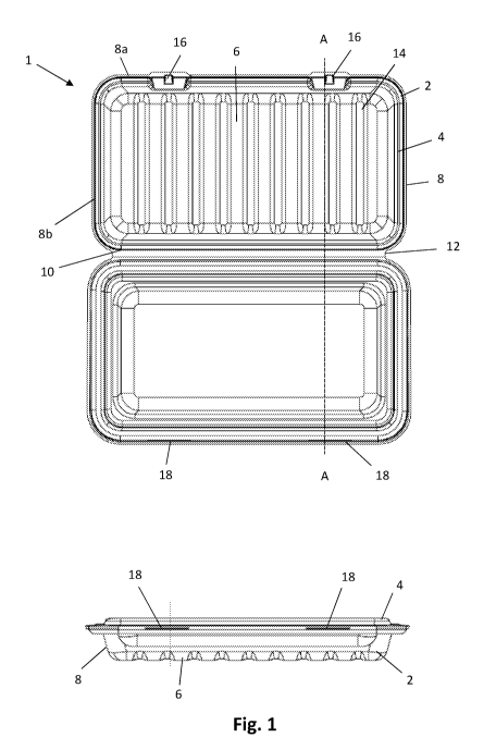
Referring to Figure 1, a container 1 for surgical instruments comprises a
container body 2
and a lid 4. The container body 2 comprises a base 6 and upstanding walls 8 a-
d defining
an open enclosure. The body 2 and lid 4 are connected along a common edge 10
corresponding to the edge 8 b of the body 2, by a hinge 12. The body 2 and lid
4 are
formed as a single piece from a moulded pulp material and the hinge 12 is a
living hinge
integrally moulded with the body 2 and lid 4.
A series of spaced corrugated ridges 14 extend across the width of the base 6
between
the side walls 8a and 8b. The ridges re-inforce the base and provide impact
absorption
for an instrument support on the base 2.
A pair of tabs 16 project from the upper edge of the outer side wall 8a of the
base 2. The
lid 4 includes a pair of corresponding slots 18 arranged to receive the tabs
16. The tabs 16
and slots 18 define a catch arrangement for holding the lid 4 in the closed
position.
CA 03019414 2018-09-28
WO 2017/168152 PCT/GB2017/050885
The lid 4 and body 2 form a clamshell arrangement, with the hinged lid fitting
over the
upper edge of the body 2 to close the container. As shown in Figure 2 the
walls 8 taper
outwardly in the upwards direction. At their upper edge the walls 8a-d curve
outwardly
and downwardly defining a curved upper lip 20 having a downwardly extending
portion
5 22 at the end of the lip 20 that is spaced outwardly from the adjacent
wall 8. A flange 24
extends horizontally outwards from the lower end of the lip 20. The lid 4
includes a roof
24 and an inner wall 26 extending downwardly from the roof 24. At the lower
end 28 of
the inner wall 26 the lid 4 curves upwardly defining an outer wall 30. The
outer wall 30 is
spaced outwardly from the inner wall 26 with a channel 32 being defined
therebetween.
10 The inner wall 26 extends downwardly to a depth whereby the lower end of
the inner
wall 26 is below the height of the upper lip 20 of the body 2 when the lid 4
is closed.
The inner wall 26 tapers outwardly in the downward direction towards the lower
edge 28.
The outer wall 30 tapers outwardly in the upward direction towards the lip 32
at the
same angle as the walls 8. Hence the outer wall 30 is configured to seat
parallel against
the inner surface of the adjacent wall 8 of the body 2. The outer wall 30
extends upwardly
to the height of the upper lip 20 and curves over and conforms to the shape of
the inner
edge of the lip 20. The lid 4 then curves downwardly defining an outer lip 32
that is
spaced outwardly of the outer edge of the lip 20. A flange 34 extends
outwardly from the
lower edge of the lip 32 and is arranged to seat on the flange 24 of the body
2, the flange
34 of the lid extending outwardly the same distance as the flange 24 of the
body, such
that the lid 4 and body 2 have the same peripheral shape. A channel 36 is
defined
between the downwardly extending lip 32 and the outer wall 30 with the lip 32
defining
the outer wall of the channel and the outer wall 30 defining the inner wall of
the channel
36. The lip 20 of the body is received within the channel 36.
The upper surface of the lip 20 seats against the inner surface of the channel
36. The
outer wall 30 is configured to nest closely against the wall 8 in a tight push
fit
arrangement. As shown in Figure 3, the tabs 16 extend outwardly from the outer
wall 8a
of the body 2 in an upwardly inclined angle to a height above the flanges 24
and 34 to the
CA 03019414 2018-09-28
WO 2017/168152 PCT/GB2017/050885
11
height of the slot 18 formed in the outer wall defining the lip 32. A
horizontal locking
portion 38 projects from the end of the tab 18 which inserts into the slot 18
to prevent
the lid 4 from lifting upwardly thereby holding the lid 4 closed.
Figure 4 shows a cross section A-A of Figure 1. The container 1 is moulded in
the open
position shown in Figure 4 from a pulp fibre material. In this horizontal
position it can be
seen that the base 28 of the channel 32 defined by the inner wall 26 and outer
wall 30 of
the lid 4 extends to a greater height than the upper rim 21 of the lip 20,
such that when
the lid 4 is folded closed the base 28 is located below the upper rim 21. The
heights of the
.. inner wall 26 and outer wall 30 may be selected such that the base 28 of
the channel 32
extends all the way to the base 6 where maximum security of the contents is
required.
The double walled arrangement formed by the inner 26 and outer 30 walls of the
lid 4
provides lateral impact cushioning for the contents of the container, and well
as effecting
a secure closures and seal with the walls 8 of the body 2.
In use an instrument is selected from storage for use in the operating theatre
and placed
into a permeable sealed bag, such as a paper/plastic peel pouch bag that is
able to
withstand a sterilisation process such as high temperature steam sterilisation
process as
used in autoclaving, or sterilisation using a gas such as ETO (ethylene oxide)
. The sealed
bag is then placed into a container 1. The container 1, including the bagged
and sealed
instrument is placed into a sterilisation unit such an autoclave chamber. The
pulp fibre
material of the container is gas permeable, meaning it allows the gas and/or
steam to
penetrate, and does not thermally shield the contents, ensuring that the
instrument is
properly exposed to the high temperature sterilisation environment. Once the
sterilisation process has been completed the sterile instrument is housed
within the
container 1 and is kept from human contact and/or contact with other
instruments during
transport to the point of use within the operating theatre. The container
thereby helps
maintain sterility as well as preventing damage to the instrument.
CA 03019414 2018-09-28
WO 2017/168152 PCT/GB2017/050885
12
Once the sterile instrument(s) has been placed in the container 1, the
container 1 may be
processed in one of the following ways at this stage:
i. A green tamper proof label indicating the instrument's "ready to use"
condition
is placed on the exterior of the container 1. A red label indicating the
instrument's "soiled
instrument" condition is placed inside the container 1 for later use.
ii. A green tamper proof label indicating the instrument's "ready to use"
condition
is placed on the exterior of the tray. The container 1 is then placed inside
of a sterile peel
pouch. A red label indicating the instrument's "soiled instrument" condition
is placed
inside the pouch for later use.
iii. A red label indicating the instrument's "soiled instrument" condition
is placed
inside the container 1 for later use. The container is then wrapped with an
approved
sterility wrap.
iv. The container 1 is placed inside of a wrapped tray or closed
container system. In
this case the container 1 is inside of a larger tray holding 70¨ 90
instruments. The Single
Cycle container 1 only holds a handful of the most delicate instruments.
The instrument is removed from the container 1 at the point of use. Following
use the
contaminated instrument may be returned to the container 1. An indicator is
provided to
indicate that the contents are used and contaminated. The indicator may be a
sleeve, a
sticker, a stamp or any other suitable means of indicating the state of the
contents. Once
the instrument has been placed within the container 1 a cleaning fluid is
applied to the
instrument to remove bulk contaminants and mitigate the impact of fluid drying
on the
instruments. The container 1 includes a surfactant proof barrier which
prevents the
surfactant solution from penetrating the pulp. The surfactant proof barrier
may include a
fluorocarbon. The fluorocarbon may be applied to the pulp within the slurry
and/or may
be applied to the pulp post-forming such as by spray application. The
surfactant proof
barrier may also or alternatively include a coating of surfactant proof resin.
The surfactant
proof resin is preferably applied to at least the inner surface of the base
prior to
the
CA 03019414 2018-09-28
WO 2017/168152
PCT/GB2017/050885
13
Following application of the cleaning fluid the lid 4 is closed to securely
contain the
instrument or instruments and a red tamper proof label is applied to the
exterior of the
tray to indicate that the instruments are contaminated and represent a
biohazard. The
tray is now in compliance to be transported through the hospital corridors.
The
instrument is transported for cleaning within the container 1 which prevents
damage to
the instrument during transit as well as preventing the spread of contaminants
and
preventing the risk of injury from the instruments. When the instrument is
removed for
cleaning on arrival at the Sterile Processing Department the container 1 may
be disposed
of, obviating the requirement for additional cleaning operations to clean and
sterilise the
.. container.