Note: Descriptions are shown in the official language in which they were submitted.
CA 03019559 2018-09-28
WO 2017/168158 PCT/GB2017/050895
GUIDE CAM ASSEMBLY FOR DIFFERENTIAL AND VARIABLE STROKE
CYCLE ENGINES
FIELD
Embodiments disclosed herein relate to internal combustion engines, and in
particular,
piston internal combustion engines. More particularly, embodiments disclosed
herein relate to a
guide cam assembly for guiding components of two-part pistons in differential
and variable-
stroke cycle internal combustion engines.
BACKGROUND AND SUMMARY
The internal combustion engine is an engine where the combustion of a fuel
occurs with
an oxidizer in a combustion chamber that is an integral part of the working
fluid flow circuit. In
an internal combustion engine the expansion of the high-temperature and high-
pressure gases
produced by combustion apply direct force to some component of the engine,
typically a piston.
This force moves the component over a distance, transforming chemical energy
into useful
mechanical energy.
In one aspect, embodiments disclosed herein relate to an engine having an
engine shaft
and a piston configured to reciprocate within a cylinder chamber having an
axis, each piston
having an first piston part and piston stem to move in unison with or
separately from a second
piston part to define piston strokes for different thermal functions of the
engine. The engine
further includes a linkage assembly having a first end coupled to the engine
and a second end
coupled to the piston stem defining a copy point, an actuator that engages the
linkage assembly,
and a guide cam that engages a guide cam follower on the linkage assembly. The
actuator and
the guide cam are operable to control motion of the linkage assembly to
thereby define
substantially linear movement of the copy point along the cylinder chamber
axis.
1
CA 03019559 2018-09-28
WO 2017/168158
PCT/GB2017/050895
BRIEF DESCRIPTION OF THE DRAWINGS
The invention is illustrated in the accompanying drawings wherein,
Figure 1 illustrates a schematic view of one embodiment of a guide cam
assembly.
Figure 2 illustrates a top view of an embodiment of coaxial actuator and guide
cams of a
guide cam assembly.
Figure 3 illustrates a schematic view of an alternate embodiment of a guide
cam assembly
incorporating a pantographic linkage assembly.
Figure 4 illustrates a schematic view an alternate embodiment of a guide cam
assembly
incorporating a movable fulcrum.
Figure 5 illustrates a schematic view of an alternate embodiment of a guide
cam
assembly.
DETAILED DESCRIPTION
Embodiments disclosed herein relate to a guide cam assembly for guiding
components of
two-part pistons in differential and variable-stroke internal combustion
engines. The engine
typically includes an engine block having one or more cylinder bores and two-
part pistons
therein. Each two-part piston includes an upper or first piston part and a
lower or second piston
part which are separable from each other. The upper piston part is in sliding
contact (or abutting)
engagement with a respective cylinder bore wall and configured to at certain
times engage the
lower piston part. A piston stem is coupled at a first end to the upper piston
part, and is hingedly
(or pivotally) coupled at a second end to a linkage assembly. The hinged
coupling (pivotal
junction) may define a 'copy' point.
The guide cam assembly may include an actuator that engages the linkage
assembly and
thereby effects or controls vertical movement of the piston stem. In one
embodiment, the
actuator may be an actuator cam configured to engage an actuator cam follower
on the linkage
2
CA 03019559 2018-09-28
WO 2017/168158
PCT/GB2017/050895
assembly and thereby effect or control vertical movement of the piston stem.
In turn, the piston
stem effects or controls vertical movement of the upper piston part, which is
also constrained by
the cylinder bore wall. Alternatively, an electronic actuator may be used to
effect or control
vertical movement of the first piston part. Other actuation mechanisms may
also be used
including, but not limited to, an electromechanical actuator operable
independently of the engine
shaft, or a hydraulic actuator. Yet other actuation mechanisms may include
means controlled
electronically during engine operation such as electro-mechanical,
electromagnetic, hydraulic,
pneumatic or devices controlled via electronic circuit or solenoid.
The guide cam assembly further generally includes a guide cam configured to
engage a
guide cam follower at a different location on the linkage assembly and thereby
control lateral
movement of the piston stem. In turn, the piston stem controls lateral
movement of the upper
piston part, which is also constrained by the cylinder bore wall. One or more
return mechanisms
may be disposed at locations on the linkage assembly to bias the linkage
assembly in a direction
substantially opposite the mating engagement between respective cams and cam
followers. A
return mechanism may include a spring, a cam, an electro-mechanical actuator,
a hydraulic
actuator, a pneumatic actuator, or an electromagnetic actuator. In certain
embodiments, multiple
actuator and guide cams are coaxial, but are not required to be, and in other
embodiments the
multiple cams are not coaxial. Cam lobes or lobe profiles of any of the cams
may be optimized
to provide various different movements of the linkage assembly to in turn
control movement of
the copy point and piston stem, and thereby the first piston part.
Figure 1 illustrates a schematic view of one embodiment of a guide cam
assembly. The
variable-stroke cycle internal combustion engine typically includes an engine
block 210 having
one or more cylinder bores 212, and an upper or first piston part 220 located
within each of the
3
CA 03019559 2018-09-28
WO 2017/168158
PCT/GB2017/050895
one or more cylinder bores 212. The upper piston part 220 may be in sliding
contact (or
abutting) engagement with a respective cylinder bore wall 213. The upper
piston part 220 is
configured to at certain times engage a lower or second piston part 222. A
piston stem 230 is
coupled at a first end 232 to the upper piston part 220, and is hingedly (or
pivotally) coupled at a
second end 234 to a piston lever-link bar 110. The hinged coupling (pivotal
junction) may
define a 'copy' point 102.
The guide cam assembly includes a linkage assembly comprising a lever-link-bar
110 and
fulcrum-link bar 112 coupled together at common ends 120. At an opposite end
from this
coupling 120, the lever-link bar 110 is coupled to the piston stem 230 at the
copy point 102, and
the fulcrum-link bar 112 is hingedly coupled to the engine block 210 at a
first hinge junction
104. The hinged coupling (pivotal junction) defines an 'anchor' (or
attachment) point 104. The
guide cam assembly further includes 1) an actuator cam 250 configured to
engage an actuator
cam follower 252 on the lever-link bar 110 and thereby control vertical
movement of the piston
stem 230, which in turn controls vertical movement of the first piston part
220; and 2) a guide
cam 260 configured to engage a guide cam follower 262 on the fulcrum-link bar
112 and thereby
control lateral movement of the piston stem 230, which in turn controls
lateral movement of the
first piston part 220. One or more return mechanisms 254, 264 may be disposed
at locations on
the lever-link bar 110 and fulcrum-link bar 112, respectively, to bias each
link in a direction
substantially opposite the mating engagement between respective cams and cam
followers.
Figure 2 illustrates a top view of coaxial actuator and guide cams of the
guide cam assembly
arranged on a common shaft.
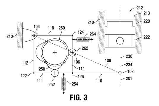
Figure 3 illustrates a schematic view of another embodiment of a guide cam
assembly.
The guide cam assembly incorporates a linkage assembly (e.g., a four-bar-
linkage) including a
4
CA 03019559 2018-09-28
WO 2017/168158
PCT/GB2017/050895
portion 111 of the piston lever-link-bar 110, a fulcrum-link bar 112, a force-
link bar 114, and a
rocker-link bar 118. In defining and locating the four-bar-linkage, the
linkage assembly may be
hingedly coupled to the engine block 210 at a first hinge junction 104 of a
first end of the
fulcrum-link bar 112 and a first end of the rocker-link bar 118. The hinged
coupling (pivotal
junction) defines an 'anchor' (or attachment) point 104. The four-bar-linkage
further includes a
second hinge junction 122 of a second end of the fulcrum-link bar 112 and a
first end of the
portion 111 of the piston lever-link-bar 110, a third hinge junction 124 of a
second end of the
rocker-link bar 118 and a first end of the force-link bar 114, and a fourth
hinge junction 126 of a
second end of the force-link bar 114 and a second end of the portion 111 of
the piston lever-link-
bar 110.
The guide cam assembly further includes 1) an actuator cam 250 configured to
engage an
actuator cam follower 252 on the lever-link bar 110 and thereby control
vertical movement of the
piston stem 230, which in turn controls vertical movement of the first piston
part 220; and 2) a
guide cam 260 configured to engage a guide cam follower 262 on the force-link
bar 114 and
thereby control lateral movement of the piston stem 230, which in turn
controls lateral movement
of the first piston part 220. The guide cam follower 262 is coupled (for
example rotatably or
pivotally) to the force-link bar 114 at an "origin" point (or axis) 106. The
"origin" point 106 is
located at the intersection between the force-link bar 114 and an imaginary
line ¨ indicated by
line 108 ¨ defined between the 'copy' point 102 and the 'anchor' point 104.
One or more return
mechanisms 254, 264 may be disposed at locations on the lever-link bar 110 and
force-link bar
114, respectively, to bias each link in a direction substantially opposite the
mating engagement
between respective cams and cam followers.
5
CA 03019559 2018-09-28
WO 2017/168158
PCT/GB2017/050895
The four-bar-linkage of the guide apparatus 100 may be configured to form a
pantographic assembly or apparatus. It will be understood by those skilled in
the art that a
pantographic assembly may be formed from mechanical linkages connected in a
manner based
on parallelograms, such that movement of one point of the assembly (for
example, the "origin"
point 106) produces respective (and possibly scaled) movements in a second
point of the
assembly (for example, the 'copy' point 102).
Figure 4 illustrates a schematic view of yet another embodiment of a guide cam
assembly. The guide cam assembly incorporates a movable fulcrum at one end of
the lever-link
bar. A lever-link bar 110 is coupled at a first end to a cam follower 262
configured as the
movable fulcrum, and at a second end to the first piston part 220 by way of
the piston stem 230
at a copy point 102. The movable cam follower 262 may be configured to move in
any direction.
Preferably, the movable cam follower 262 may move in a direction substantially
perpendicular to
the cylinder axis 201. The guide cam assembly further includes 1) an actuator
cam 250
configured to engage an actuator cam follower 252 on the lever-link bar 110
and thereby control
vertical movement of the piston stem 230, which in turn controls vertical
movement of the first
piston part 220; and 2) a guide cam 260 configured to engage the movable cam
follower 262 and
thereby control lateral movement of the piston stem 230, which in turn
controls lateral movement
of the first piston part 220. A return mechanism 254 may be disposed at a
location on the lever-
link bar 110 to bias the lever-link bar 110 in a direction substantially
opposite the mating
engagement between the actuator cam 250 and cam follower 252.
Figure 5 illustrates a schematic view of yet another embodiment of a guide cam
assembly. The guide cam assembly includes a linkage assembly comprising a
lever-link-bar 110
and fulcrum-link bar 112 coupled together at common ends 120. At an opposite
end from this
6
CA 03019559 2018-09-28
WO 2017/168158
PCT/GB2017/050895
coupling 120, the lever-link bar 110 is coupled to the piston stem 230 at the
copy point 102, and
the fulcrum-link bar 112 is hingedly coupled to the engine block 210 at a
first hinge junction
104. The hinged coupling (pivotal junction) defines an 'anchor' (or
attachment) point 104. The
guide cam assembly further includes an actuator 250 configured to engage the
lever-link bar 110
and thereby control vertical movement of the piston stem 230, which in turn
controls vertical
movement of the first piston part 220. The actuator 250 may be any type of
actuator, including
but not limited to, an electronic actuator, an electromechanical actuator
operable independently
of the engine shaft, a hydraulic actuator, a pneumatic actuator, an electro-
mechanical actuator, an
electromagnetic actuator, an actuator controlled via electronic circuit or
solenoid, or any other
type capable of effecting movement of the linkage assembly. The guide cam
assembly further
includes a guide cam 260 configured to engage a guide cam follower 262 on the
fulcrum-link bar
112 and thereby control lateral movement of the piston stem 230, which in turn
controls lateral
movement of the first piston part 220. The guide cam follower 262 may be
rigidly coupled to the
fulcrum-link bar 112 by a linkage 263. A return mechanism 254 may be disposed
at a location
on the lever-link bar 110 to bias the lever-link bar in a direction
substantially opposite movement
of the actuator 250. A return mechanism 264 may be disposed at a location on
the fulcrum-link
bar 112 to bias the fulcrum-link bar 112 in a direction substantially opposite
the mating
engagement between the guide cam 260 and the guide cam follower 262.
A method of operating a differential-stroke or variable-stroke reciprocating
internal
combustion engine, the engine having an engine shaft and a piston configured
to reciprocate
within a cylinder chamber having an axis, each piston having a first piston
part and piston stem
operable to move in unison with or separately from a second piston part to
define piston strokes
for different thermal functions of the engine, includes providing a linkage
assembly having a first
7
CA 03019559 2018-09-28
WO 2017/168158
PCT/GB2017/050895
end coupled to the engine and a second end coupled to the piston stem defining
a copy point, an
actuator that engages the linkage assembly, and a guide cam configured to
engage a guide cam
follower on the linkage assembly, wherein the actuator and guide cam are
operable to control
motion of the linkage assembly to thereby define substantially linear movement
of the copy point
along the cylinder chamber axis.
Reference throughout this specification to "one embodiment" or "an embodiment"
or
"certain embodiments" means that a particular feature, structure or
characteristic described in
connection with the embodiment is included in at least one embodiment of the
present
disclosure. Therefore, appearances of the phrases "in one embodiment" or "in
an embodiment"
or "in certain embodiments" in various places throughout this specification
are not necessarily all
referring to the same embodiment, but may. Furthermore, the particular
features, structures or
characteristics may be combined in any suitable manner, as would be apparent
to one of ordinary
skill in the art from this disclosure, in one or more embodiments.
In the claims below and the description herein, any one of the terms
comprising,
comprised of or which comprises is an open term that means including at least
the
elements/features that follow, but not excluding others. Therefore, the term
comprising, when
used in the claims, should not be interpreted as being limitative to the means
or elements or steps
listed thereafter. Any one of the terms including or which includes or that
includes as used
herein is also an open term that also means including at least the
elements/features that follow
the term, but not excluding others. Accordingly, including is synonymous with
and means
.. comprising.
It should be understood that the term "coupled," when used in the claims,
should not be
interpreted as being limitative to direct connections only. "Coupled" may mean
that two or more
8
CA 03019559 2018-09-28
WO 2017/168158
PCT/GB2017/050895
elements are either in direct physical, or that two or more elements are not
in direct contact with
each other but yet still cooperate or interact with each other. "Coupled" may
mean a rigid
coupling, hinged coupling, pivotal coupling, and others.
Although one or more embodiments of the present disclosure have been described
in
detail, it will be apparent to those skilled in the art that many embodiments
taking a variety of
specific forms and reflecting changes, substitutions and alterations may be
made without
departing from the scope of the invention as set out in the claims. The
described embodiments
illustrate the scope of the claims but do not restrict the scope of the
claims.
9