Note: Descriptions are shown in the official language in which they were submitted.
POWER SUPPLY CONNECTION DEVICE, AND CHARGING-DISCHARGING
CONTROL METHOD FOR SAME
[0001] The present application claims the priority of Chinese patent
applications CN201610343620.4,
CN201620472328.8, CN201610339975.6, and CN201620467454.4 with the filing date
of 20 May 2016.
Field of invention
[0002] The present invention relates to the field of electrical control, and
in particular to a power supply
access device and a charging-discharging control method for same.
Prior arts
[0003] The rapid expansion of semiconductor power devices, the maturity of
modern control theory, and
the intelligent development of power systems have brought about an opportunity
for the development of
micro-grid apparatuses in a micro-grid system.
[0004] In a typical intelligent micro-grid system, in order to securely and
efficiently access and make full
use of distributed energy, including a rectifier, an inverter, a direct-
current converter, an unloader and an
energy storage unit, as shown in Fig. 1, electric energy generated by a fan
and a photovoltaic assembly
charges the energy storage unit, and the energy storage unit is discharged to
supply power to a direct-current
or alternating-current load.
[0005] By means of such a structure, during a power supply process of the
micro-grid, the energy storage
unit is continuously charged and discharged, and since the number of times of
charging and discharging of
the energy storage unit is limited, the energy storage unit will be scrapped
after having been used for a
period of time, and must be replaced, resulting in a relatively high running
cost of the micro-grid system.
[0006] In addition, the inverter, the direct-current converter and the
unloader are often each configured
with a separate controller for control, and the various devices in the system
are relatively dispersed, such
that the micro-grid system occupies a larger space and the running cost is
further increased.
Content of the present invention
[0007] In view of the problems existing in the prior art, the object of the
present invention is to provide
a power supply access device, which reduces the number of times of charging
and discharging of an energy
storage unit by changing a connection mode of the energy storage unit, thus
prolonging the service life of
the energy storage unit, decreasing running costs of a micro-grid system
constituted by the power supply
access device, and ensuring stable and reliable supplying of power to the
micro-grid system.
1
CA 3019619 2020-03-20
CA 03019619 2018-10-01
[0008] The present invention provides a power supply access device for
accessing a
power generation unit and an energy storage unit and supplying power to a
load. The
power supply access device comprises a rectifier, a direct-current converter,
an unloader,
and an inverter. The rectifier is used to rectify an input from the power
generation unit.
The direct-current converter is used to boost an input from the energy storage
unit, the
input from the power generation unit, or the rectified input from the power
generation
unit. The unloader is used to release excess energy. The inverter is used to
convert direct
current into alternating current. The power supply access device further
comprises a
charging-discharging control device and a controller, wherein the charging-
discharging
control device is used to control the discharging or charging of the energy
storage unit.
The controller controls the charging-discharging control device.
[0009] Further, the controller is connected to the direct-current converter,
the unloader
and the inverter; the controller is used to control the direct-current
converter, the
unloader and the inverter; the unloader is connected to the direct-current
converter and
the inverter; and the unloader is mounted on a high-voltage bus between the
direct-
current converter and the inverter.
[0010] Further, the charging-discharging control device is arranged between
the
energy storage unit and the high-voltage bus.
[0011] Further, the direct-current converter is a BOOST circuit.
[0012] Further, a positive electrode of the energy storage unit is connected
to the
charging-discharging control device via an inductor of the BOOST circuit, and
then
connected to the high-voltage bus via the charging-discharging control device.
[0013] Further, the direct-current converter is a bidirectional BUCK-BOOST
circuit.
[0014] Further, the positive electrode of the energy storage unit is connected
to a first
terminal of an inductor of the bidirectional BUCK-BOOST circuit via a parallel
circuit
of a second controllable switch and an unidirectionally-conducted diode, the
other
terminal of the inductor is grounded, and the charging-discharging control
device is
connected between the first terminal of the inductor and the high-voltage bus.
[0015] Further, the second controllable switch is used to control whether to
access the
energy storage unit.
[0016] Further, controlling whether to access the energy storage unit
comprises:
[0017] when the power of electricity generated by the power generation unit is
greater
than a product of a load power and a first coefficient, if the energy storage
unit is not
fully charged, charging the energy storage unit, and if the energy storage
unit is fully
charged, switching out the energy storage unit, and activating the unloader;
[0018] when the power of the electricity generated by the power generation
unit is less
than a product of the load power and a second coefficient, switching in the
energy
storage unit, so that the energy storage unit is discharged, and the energy
storage unit
supplies power to the load together with the power generation unit; and
2
CA 03019619 2018-10-01
[0019] when the power of the electricity generated by the power generation
unit is
greater than or equal to the product of the load power and the second
coefficient and
less than or equal to the product of the load power and the first coefficient,
switching
out the energy storage unit.
[0020] Further, the charging-discharging control device comprises a
unidirectional
channel and a controllable channel connected in parallel, wherein when the
controllable
channel is disconnected, the energy storage unit is discharged via the
unidirectional
channel, and when the controllable channel is conducted, the energy storage
unit is
charged via the controllable channel.
[0021] Further, the controllable channel is provided with a first controllable
switch,
and the unidirectional channel is provided with a diode for unidirectional
conduction.
[0022] Further, the power supply access device comprises one or more sets of
energy
storage unit access terminals.
[0023] Further, the energy storage unit access terminals are used to access
energy
storage units having the same charging and discharging properties.
[0024] Further, the energy storage unit access terminals are used to access
energy
storage units having different charging and discharging properties, and the
controller
discharges the energy storage unit with different priorities or at different
frequencies.
[0025] Further, the controller has a battery management function.
[0026] Further, the battery management function comprises:
[0027] estimating a state of charge of the energy storage unit; and
[0028] collecting terminal voltages as well as charging and discharging
current in real
time during charging and discharging processes of the energy storage unit.
[0029] Further, some or all of the rectifier, the direct-current converter,
the unloader
and the inverter are arranged on the same PCB board.
[0030] The present invention further provides a charging-discharging control
method
for the power supply access device, comprising the steps of:
[0031] (a) when the power of electricity generated by the power generation
unit is
greater than the product of the load power and the first coefficient, if the
energy storage
unit is not fully charged, controlling the charging of the energy storage
unit, and if the
energy storage unit is fully charged, switching out the energy storage unit,
and
activating the un loader;
[0032] (b) when the power of the electricity generated by the power generation
unit is
less than the product of the load power and the second coefficient,
controlling the
discharging of the energy storage unit, so that the energy storage unit
supplies power to
the load together with the power generation unit; and
3
CA 03019619 2018-10-01
[0033] (c) when the power of the electric power generated by the power
generation
unit is greater than or equal to the product of the load power and the second
coefficient
and less than or equal to the product of the load power and the first
coefficient,
switching out the energy storage unit.
[0034] Further, the first coefficient is greater than or equal to the second
coefficient.
[0035] Compared with the prior art, the power supply access device and the
charging-
discharging control method for same provided in the present invention have the
following beneficial effects: reducing the number of times of charging and
discharging
of an energy storage unit by changing a connection mode of the energy storage
unit,
thus prolonging the service life of the energy storage unit, decreasing a
running cost of
a micro-grid system constituted by the power supply access device, and
ensuring stable
and reliable supplying of power to the micro-grid system. In addition, by
sharing a
controller with the direct-current converter, the unloader and the inverter,
and arranging
some or all of the rectifier, the direct-current converter, the unloader and
the inverter on
the same PCB board, the present invention further reduces redundant
components,
space and costs.
Brief description of the drawings
[0036] Fig. 1 is a schematic structural diagram of a power supply access
device in the
prior art;
[0037] Fig. 2 is a schematic structural diagram of a power supply access
device of an
embodiment of the present invention;
[0038] Fig. 3 is a circuit diagram of a bidirectional BUCK-BOOST circuit and a
charging-discharging control device;
[0039] Fig. 4 is one circuit diagram of a BOOST circuit and a charging-
discharging
control device;
[0040] Fig. 5 is another circuit diagram of a BOOST circuit and a charging-
discharging control device; and
[0041] Fig. 6 is a schematic structural diagram of a power supply access
device of a
still further embodiment of the present invention.
Detailed description of the preferred embodiment
[0042] As shown in Fig. 2, a power supply access device of an embodiment of
the
present invention is used to access a power generation unit and an energy
storage unit,
and supply power to a load. The power supply access device comprises a
rectifier, a
direct-current converter, an unloader, an inverter and a controller. The
rectifier is used
to rectify an input from the power generation unit. The direct-current
converter is used
to boost an input from the energy storage unit, the input from the power
generation unit,
or the rectified input from the power generation unit. The unloader is used to
release
excess energy. The inverter is used to convert direct current into alternating
current. The
4
CA 03019619 2018-10-01
power supply access device further comprises a charging-discharging control
device for
controlling the charging or discharging of the energy storage unit. The
controller
controls the charging-discharging control device.
[0043] The power generation unit may be a direct-current power generation
device
and/or an alternating-current power generation device.
[0044] There may be one or more power generation units.
[0045] In this embodiment, there are two power generation units, and the power
generation unit comprises a direct-current power generation device and an
alternating-
current power generation device, wherein the direct-current power generation
device is
a photovoltaic assembly, and the alternating-current power generation device
is a fan.
Of course, the alternating-current power generation device may also be a
diesel
generator, and of course, may also only comprise a fan, or only comprise the
photovoltaic assembly, which is not limited in the present invention.
[0046] In this embodiment, the energy storage unit is a lead-acid battery. The
energy
storage unit may also be a battery, such as a lead-acid battery, a lithium
battery, a liquid
flow battery or a sodium-sulfur battery, which is not limited in the present
invention.
[0047] The power supply access device further comprises a controller, wherein
the
controller is connected to the direct-current converter, the unloader and the
inverter for
controlling the direct-current converter, the unloader, the inverter and a
charging-
discharging control device. The direct-current converter, the unloader, the
inverter and
the charging-discharging control device share a controller, so that redundant
components and costs can be reduced.
[0048] The charging-discharging control device is arranged between the energy
storage unit and the high-voltage bus.
[0049] The unloader is connected to the direct-current converter and the
inverter, and
the unloader is mounted on a high-voltage bus between the direct-current
converter and
the inverter.
[0050] Some or all of the rectifier, the direct-current converter, the
unloader and the
inverter are arranged on the same PCB board, thereby achieving the beneficial
effects
of reducing the space and reducing the cost.
[0051] In this embodiment, a circuit is as shown in Fig. 3, in which the
direct-current
converter is a bidirectional BUCK-BOOST circuit; and a positive electrode of
the
energy storage unit is connected to a first terminal of an inductor L of the
bidirectional
BUCK-BOOST circuit via a parallel circuit of a second controllable switch Q2
and an
unidirectionally-conducted diode D2, and the other terminal of the inductor L
is
grounded; and the charging-discharging control device comprising a first
controllable
switch Q1 and a unidirectionally-conducted diode D1 is connected between the
first
terminal of the inductor L and the high-voltage bus.
[0052] The charging-discharging control device comprises a unidirectional
channel
CA 03019619 2018-10-01
and a controllable channel connected in parallel, wherein when the
controllable channel
is disconnected, the energy storage unit is discharged via the unidirectional
channel,
that is, outputting a power to the load; and when the controllable channel is
conducted,
the energy storage unit is charged via the controllable channel.
[0053] Specifically, the controllable channel is provided with the first
controllable
switch Q1 , the unidirectional channel is provided with the diode D1 for
unidirectional
conduction, and the controller controls switch-off and switch-on of the first
controllable
switch Ql via a control terminal A.
[0054] A charging-discharging control method for a power supply access device
in
this embodiment comprises the steps of:
[0055] (a) when the power of electricity generated by the power generation
unit is
greater than the product of the load power and the first coefficient, if the
energy storage
unit is not fully charged, controlling the charging of the energy storage
unit, and if the
energy storage unit is fully charged, switching out the energy storage unit,
and
activating the unloader;
[0056] (b) when the power of the electricity generated by the power generation
unit is
less than the product of the load power and the second coefficient,
controlling the
discharging of the energy storage unit, so that the energy storage unit
supplies power to
the load together with the power generation unit; and
[0057] (c) when the power of the electric power generated by the power
generation
unit is greater than or equal to the product of the load power and the second
coefficient
and less than or equal to the product of the load power and the first
coefficient,
switching out the energy storage unit.
[0058] The second controllable switch Q2 is used to control whether to access
the
energy storage unit, with the specific control process being as follows:
[0059] (1) when PIN > ylPOUT, if the energy storage unit is fully charged,
switching
out the energy storage unit, and activating an unloader to release excess
power; charging
the energy storage unit if the energy storage unit is not fully charged,
[0060] wherein specifically, if the energy storage unit is fully charged. the
controller
turns off a PWM signal at a control terminal A of the first controllable
switch Ql, while
turning off a PWM signal at a control terminal B of the second controllable
switch Q2,
so that the first controllable switch Q1 and the second controllable switch Q2
arc both
in a switch-off state, and the energy storage unit is switched out to avoid
overcharging
of the energy storage unit, so as to extend the service life of the energy
storage unit;
[0061] and if the energy storage unit is not fully charged, the controller
turns on the
PWM signal at the control terminal A of the first controllable switch Q1,
while turning
off the PWM signal at the control terminal B of the second controllable switch
Q2, so
that the first controllable switch QI is in a switch-on state while the second
controllable
switch Q2 is in a switch-off state, and electricity generated by the power
generation unit
6
CA 03019619 2018-10-01
is input to the high-voltage bus to charge the energy storage unit by the high-
voltage
bus;
[0062] (2) when 92POUT PIN 91 POUT, switching out the energy storage unit,
and only the power generation unit supplying power to the load, so as to
achieve power
balance and reduce the number of times of charging and discharging of the
energy
storage unit, thereby extending the service life of the energy storage unit,
[0063] wherein specifically, the controller turns off the PWM signal at the
control
terminal A of the first controllable switch Q1 while turning off the PWM
signal at the
control terminal B of the second controllable switch Q2, so that the first
controllable
switch Ql and the second controllable switch Q2 are both in a switch-off
state, and the
energy storage unit is switched out;
[0064] (3) when PIN < p2POUT, switching in the energy storage unit,
discharging the
energy storage unit, and supplying power to the load together with the power
generation
unit, so as to achieve power balance,
[0065] wherein specifically, the controller turns off the PWM signal at the
control
terminal A of the first controllable switch Q1 while turning on the PWM signal
at the
control terminal B of the second controllable switch Q2, such that the first
controllable
switch Ql is in a switch-off state while the second controllable switch Q2 is
in a switch-
on state, and the energy storage unit is switched in; and
[0066] wherein PIN is the power of electricity generated by the power
generation unit,
and POUT is a load power. pi is a first coefficient, and 92 is a second
coefficient, which
may be the same or different.
[0067] When pl is the same as p2, for example, 91 = 1, 92 = 1, and at this
moment,
when PIN is less than POUT, the energy storage unit is discharged and supplies
power
to the load together with the power generation unit; when PIN is equal to
POUT, the
energy storage unit is switched out; and when PIN is greater than POUT, if the
energy
storage unit is fully charged, the energy storage unit is switched out to
avoid
overcharging of the energy storage unit and extend the service life of the
energy storage
unit, and if the energy storage unit is not fully charged, excess power is
used to charge
the energy storage unit.
[0068] In order to avoid frequent switching in the case where PIN is
approximately
equal to POUT, that is, slightly smaller than POUT, the energy storage unit is
discharged,
then PIN is slightly larger than POUT, the energy storage unit is switched out
or the
energy storage unit is charged, different pl and p2 can be used, wherein pi is
larger
than p2, for example, pl = 1.05 and cp2 = 1, and at this moment, when PIN is
less than
POUT, the energy storage unit is discharged and supplies power to the load
together
with the power generation unit; when PIN is greater than 1.05 times POUT, the
corresponding operation is performed depending on whether the energy storage
unit is
fully charged; and when PIN is between POUT and 1.05 times and POUT, the
energy
storage unit is switched out, that is to say, the power of the electricity
generated by the
7
CA 03019619 2018-10-01
power generation unit is balanced with the load power.
[0069] In another embodiment, by means of a circuit as shown in Fig. 4, the
direct-
current converter is a BOOST circuit, and a positive electrode of the energy
storage unit
is connected to the charging-discharging control device via an inductor L of
the BOOST
circuit, and then connected to the high-voltage bus via the charging-
discharging control
device. Specifically, the first controllable switch Q1 is connected in
parallel with the
unidirectionally-conducted diode D1, and then connected between the inductor L
and
the high-voltage bus.
[0070] The first controllable switch Q I can use IGBT and MOS transistors, and
if the
IGBT and MOS transistors themselves have unidirectionally-conducted diodes, it
is not
necessary to separately arrange a unidirectionally-conducted diode at this
moment;
however, if the current is relatively large, the unidirectionally-conducted
diode may also
be arranged separately.
[0071] In another embodiment, by means of a circuit as shown in Fig. 5, the
direct-
current converter is a BOOST circuit, and the first controllable switch Q1 can
use a
bidirectional thyristor.
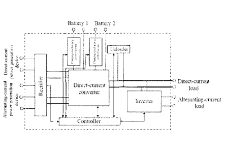
[0072] In this embodiment, the power supply access device comprises a set of
energy
storage unit access terminals, and in another embodiment, as shown in Fig. 6,
the power
supply access device comprises two sets of energy storage unit access
terminals, and is
capable of accessing two sets of energy storage units: a battery 1 and a
battery 2,
wherein the battery 1 and battery 2 respectively control charging and
discharging via
charging and discharging control devices, and when the difference between the
power
of the load and that of the electricity generated by the power generation unit
is
substantial, two sets of batteries can be simultaneously used for discharging
to output a
power, so as to ensure stable power supplying of a power supply system;
alternatively,
when one set of batteries is charged, the other set of batteries is used for
discharging to
output a power.
[0073] Of course, the power supply access device may also comprise a set of
energy
storage unit access terminals, which is not limited in the present invention.
[0074] By means of the power supply access device in this embodiment, multiple
sets
of energy storage unit access terminals can access energy storage units having
the same
or different charging and discharging properties, for example, all accessing
lead-acid
batteries, and may also respectively access the lead-acid battery and a
lithium battery,
wherein the lithium battery is more suitable for frequent charging and
discharging, and
therefore, during a power supply process, the lithium battery is
preferentially used; or
the lead-acid battery and the lithium battery are discharged at different
frequencies.
[0075] A battery management system (BMS) is mainly to improve the utilization
rate
of a battery, prevent overcharging and overdischarging of the battery, extend
the service
life of the battery, and monitor the state of the battery.
[0076] In this embodiment, the controller achieves the following functions of
the
8
CA 03019619 2018-10-01
BMS:
[0077] (1) estimating a state of charge (SOC) of the energy storage unit, that
is, the
remaining electric quantity of the energy storage unit, and ensuring that the
SOC is
maintained within a reasonable range, thereby preventing a damage caused to
the
energy storage unit due to overcharging or overdischarging; and
[0078] (2) collecting terminal voltages as well as charging and discharging
current in
real time during charging and discharging processes of the energy storage
unit, thereby
preventing the occurrence of an overcharging or overdischarging phenomenon of
the
battery.
[0079] The controller achieves the BMS function, which may effectively save 3%
of
the battery service life, thereby reducing the cost of the overall apparatus.
[0080] The preferred specific embodiments of the present invention are
described in
detail above. It should be understood that numerous modifications and changes
can be
made by a person skilled in the art according to the concept of the present
invention
without involving any inventive effort. Hence, any technical solution that can
be
obtained by a person skilled in the art according to the concept of the
present invention
on the basis of the prior art by means of logic analysis, reasoning or limited
experiments
should be within the protection scope determined by the claims.
9